Computer Aided design
This week I worked on defining my final project idea and started to getting used to the documentation process.
Research
Computer Aided Design (CAD) is the use of computer software to create, modify, analyze, and optimize designs for
a wide range of applications. CAD software enables designers and engineers to create 2D and 3D models of physical
objects, such as buildings, products, and mechanical parts, and to simulate and test their functionality in a
virtual environment.
2. Fusion 360
Introduction

Fusion 360 could be used extensively to create a detailed 3D model of the robot. The software's integrated design
and
simulation capabilities allowed me to iterate on the design and ensure functionality before moving to the physical
prototype stage.
One of the main advantages of Fusion 360 is its integrated design and simulation capabilities. The software
allows users to create complex designs, such as assemblies and parts, and to simulate their functionality in a
virtual environment. This can help designers and engineers identify potential issues early in the design process
and make necessary adjustments before creating physical prototypes or going into production.
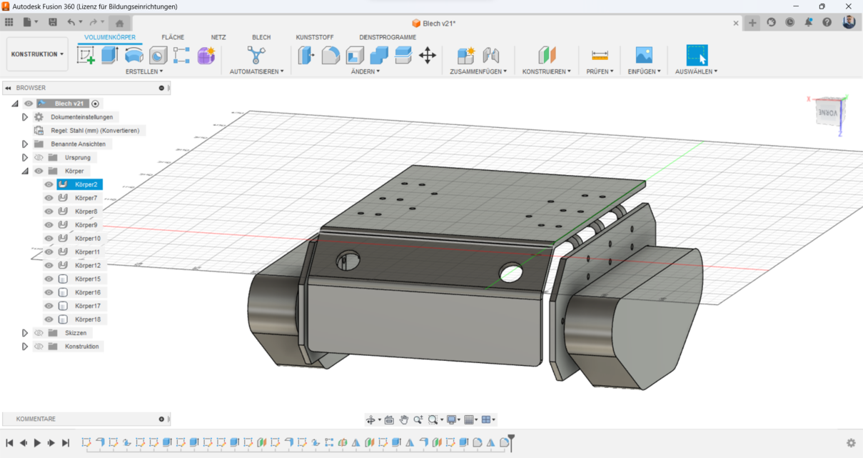
For todays assignment, i designed a Differential Tracked Robot that should be made of metal sheet later.
Creating a 3D model of a differential tracked robot
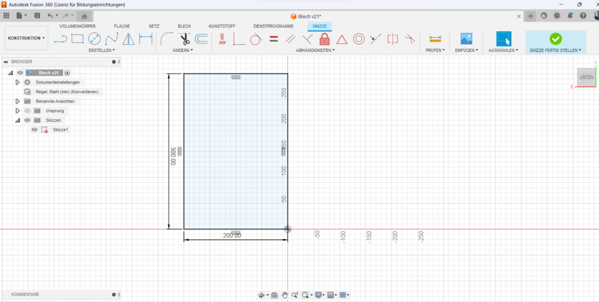
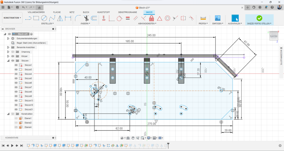
1. Initial Sketch: I started by creating the initial sketch to design the platform of the robot, focusing on the
overall dimensions and placement of key components
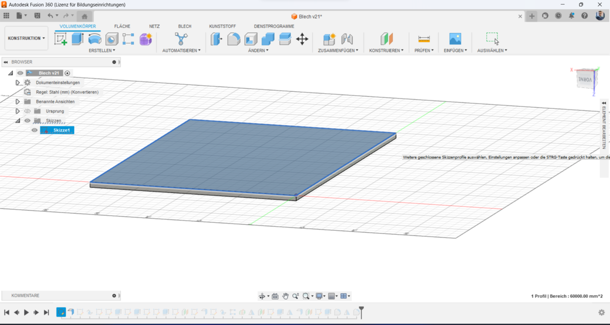
2. Conversion to Metal Sheet: I then converted the initial sketch into a metal sheet, which helped define the
structural layout and ensured it would be sturdy and manufacturable.
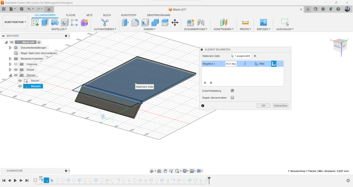
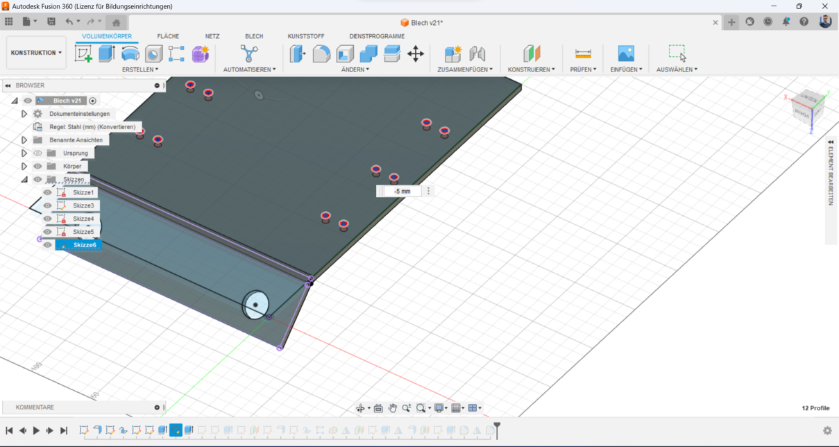
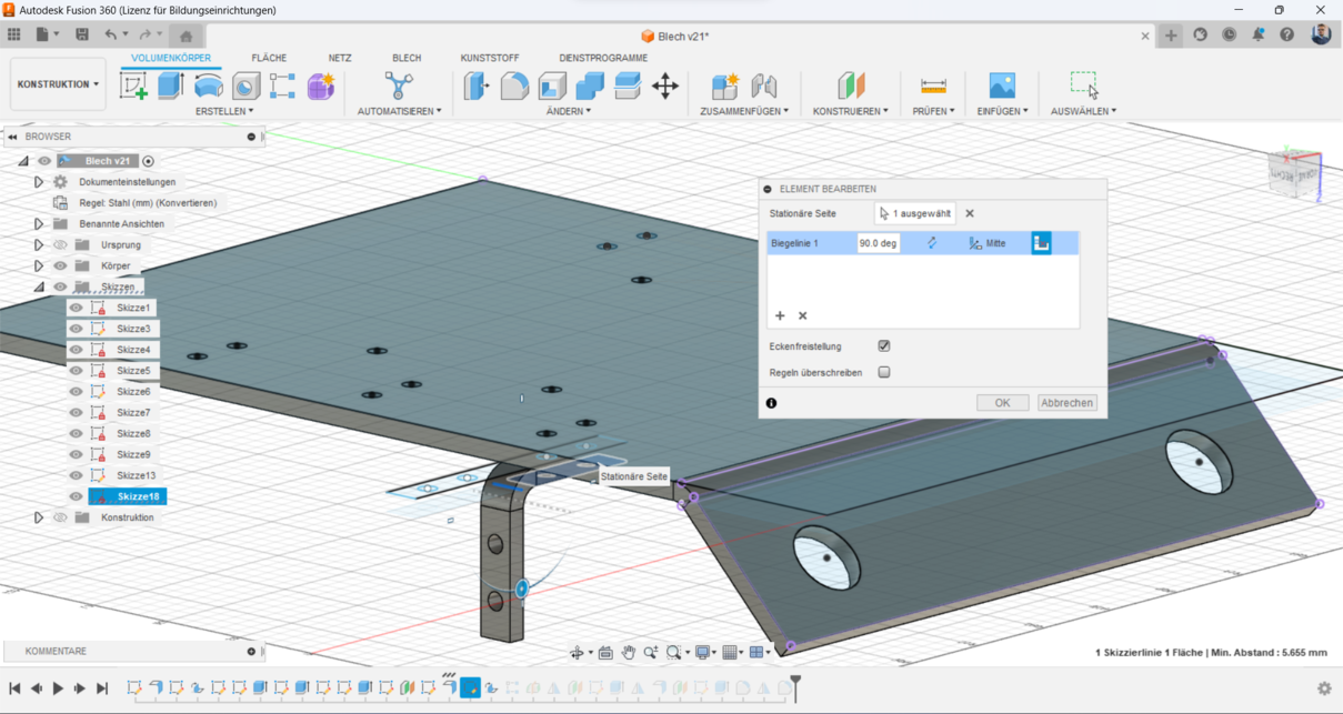
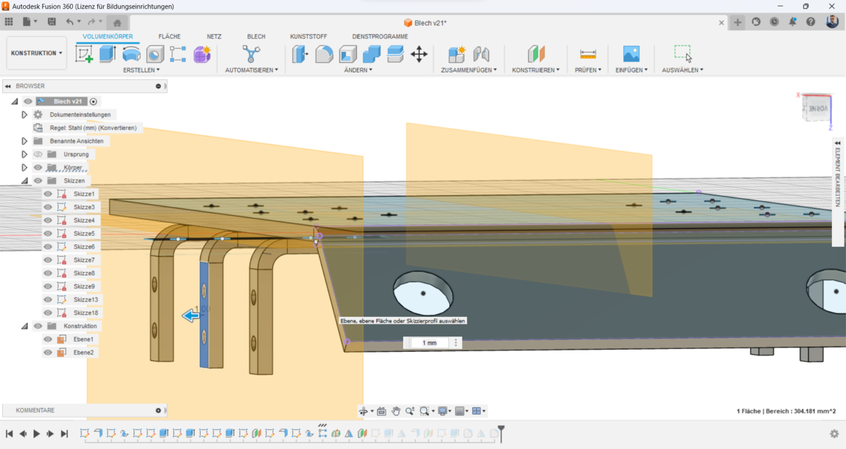
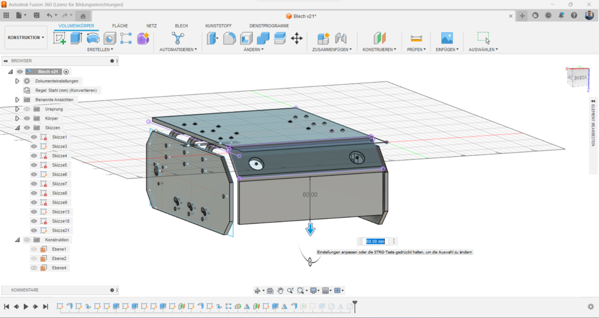
3. Bending the Platform: After defining the platform, I bent the top section to a 45-degree angle to shape it to
the form I want:
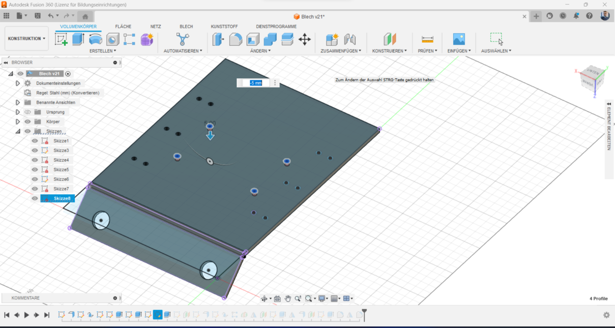
4.Drills for Screws: I created precise drill holes for screws, which are essential for securely assembling the
various components of the robot.
>
5. PCB Mounting Holes: I added specific holes for mounting the PCB, ensuring that the electronic components are
fastened.
>
6. PCB Mounting Holes: I added specific holes for mounting the PCB, ensuring that the electronic components are
securely fastened.
7. Connection Bodies: I designed L-shaped connection bodies to link the top and side platforms, adding support
and stability to the structure.
8. Bending Connection Bodies: I bent these L-shaped bodies to a 90-degree angle.
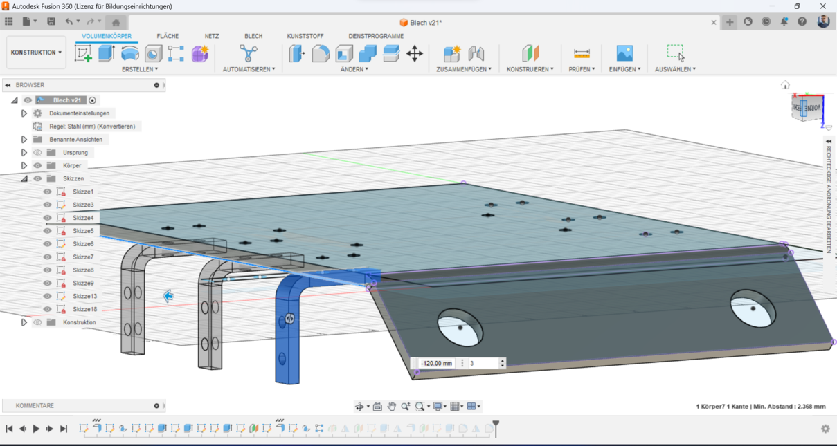
9. Replication of Connection Bodies: Once the connection bodies were perfected, I replicated them on the right side
to ensure a symmetrical design.
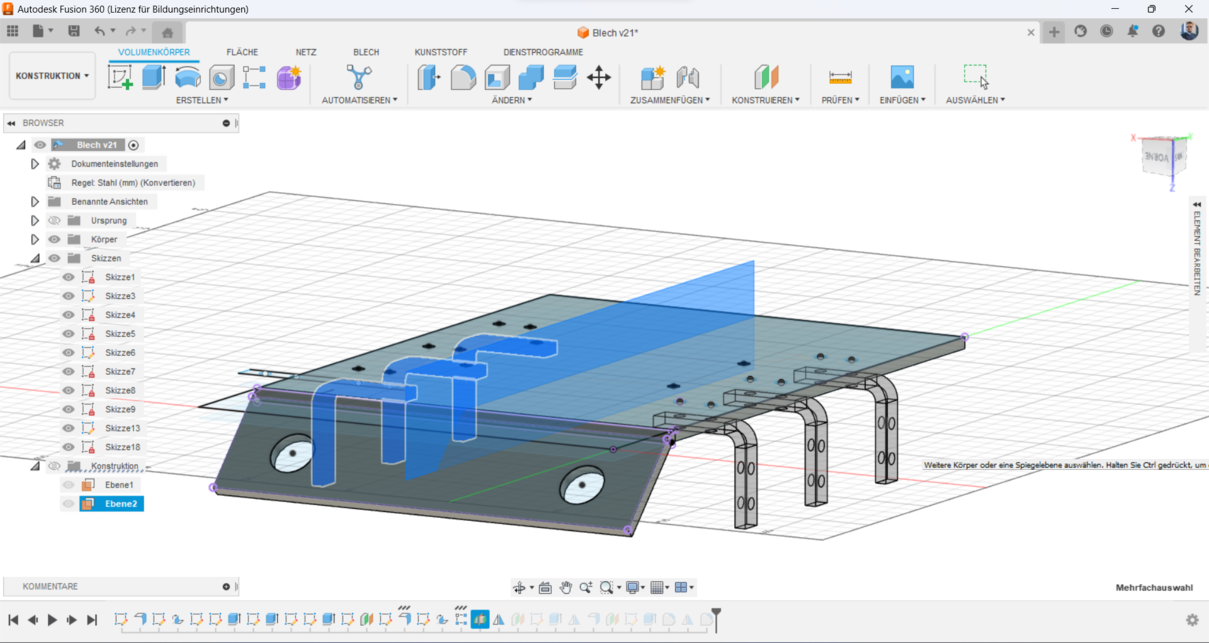
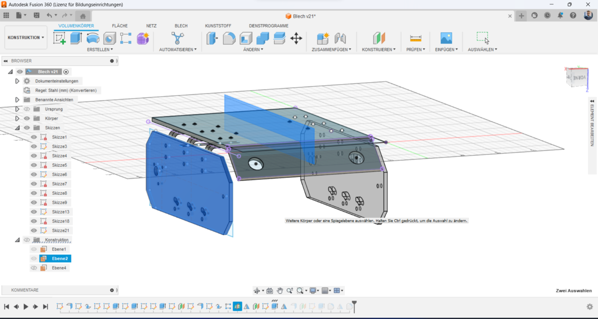
10. Mirroring the Design: I used a mid-plane to mirror the connection bodies onto the other side of the platform.
11. I mirrored the connections-bodies using the created mid-plane.
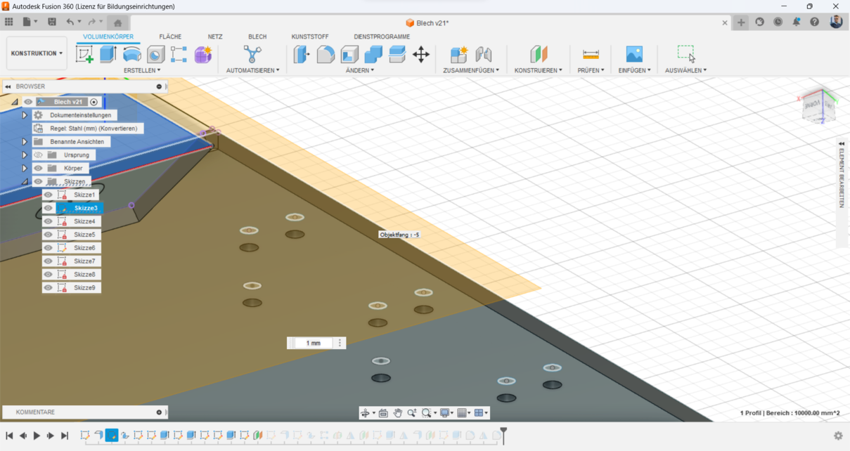
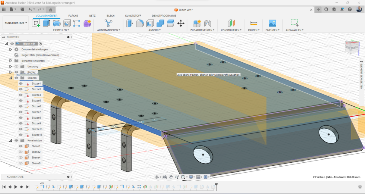
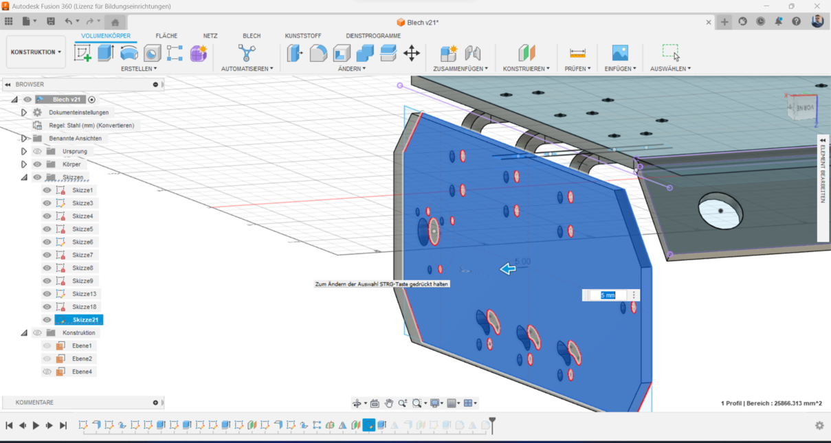
12. Offset Planes for Sketching: I created offset planes to accurately sketch the side panels, allowing for precise
alignment and correct placement of additional components.
13. I draw the sketch of the side-panels with all the drills that should have, in order to be connected to the
Track-components.
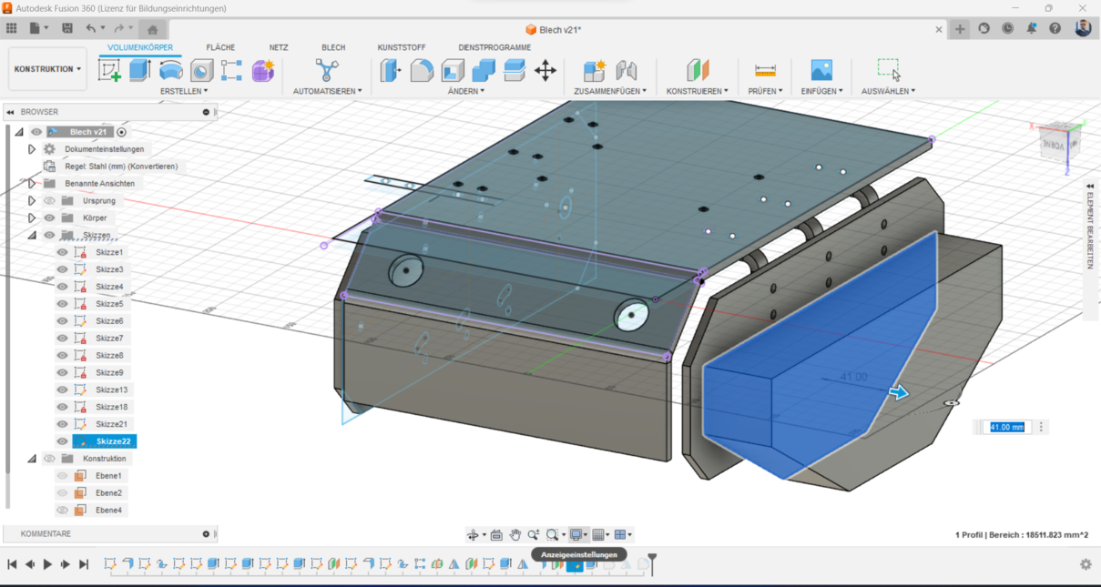
14. Extrusion of Side Panels: I then extruded the side panel sketches to form the solid platform, creating a sturdy
base for the robot.
15. Using the same methode above, I created a mid-plane to mirror the side-panels.
16. Modifications: I made several modifications throughout the process to refine the design.
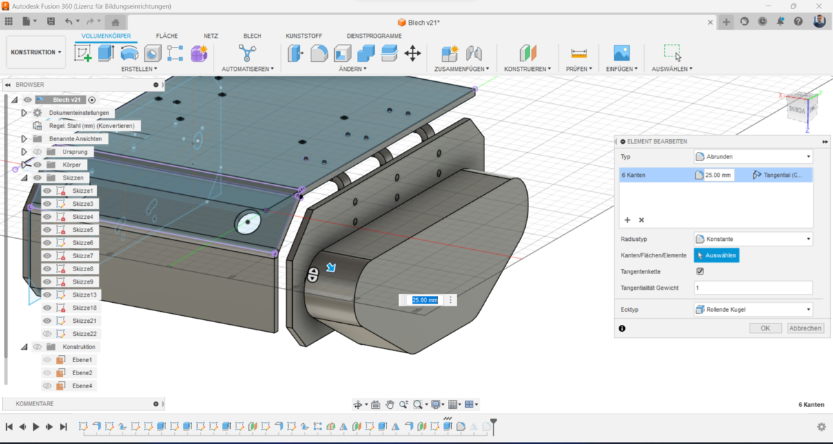
17. I created the form of the track, this one should be designed later. Or I will use a pre-fabricated one.
18. Track Form Design: I designed the form for the tank tracks, with the flexibility to use pre-fabricated tracks or
custom-designed ones depending on specific needs.
2. AutoCAD 2D
AutoCAD is a Computer-Aided Design (CAD) software developed by Autodesk. It is widely used for creating
2D-drawings. AutoCAD 2D focuses specifically on the creation, modification of
two-dimensional designs.
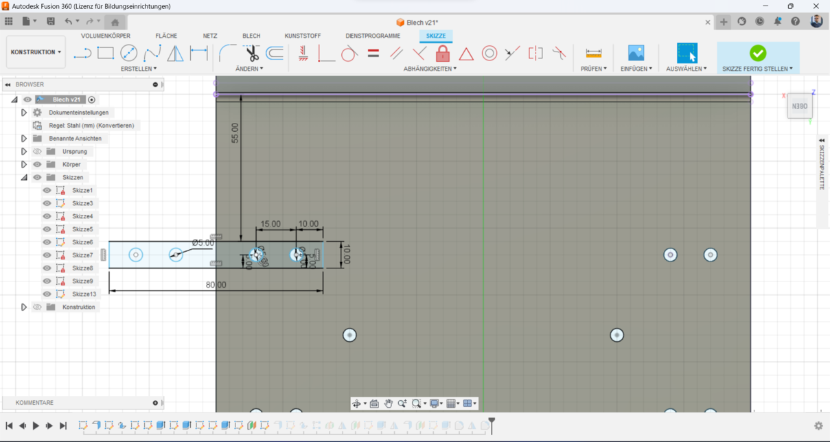
Since I needed to draw a part in 2D, I decided to focus on the leg that holds the track-tire of the robot.
Initially, I designed this component in Fusion 360, where I created a detailed 2D sketch and then extruded it to
form a 3D model and finaly convert it to metal sheet.
Now, my next step is to replicate this design in AutoCAD in 2D. This involves translating the detailed dimensions
and geometric features from the 3D model into a precise 2D technical drawing.
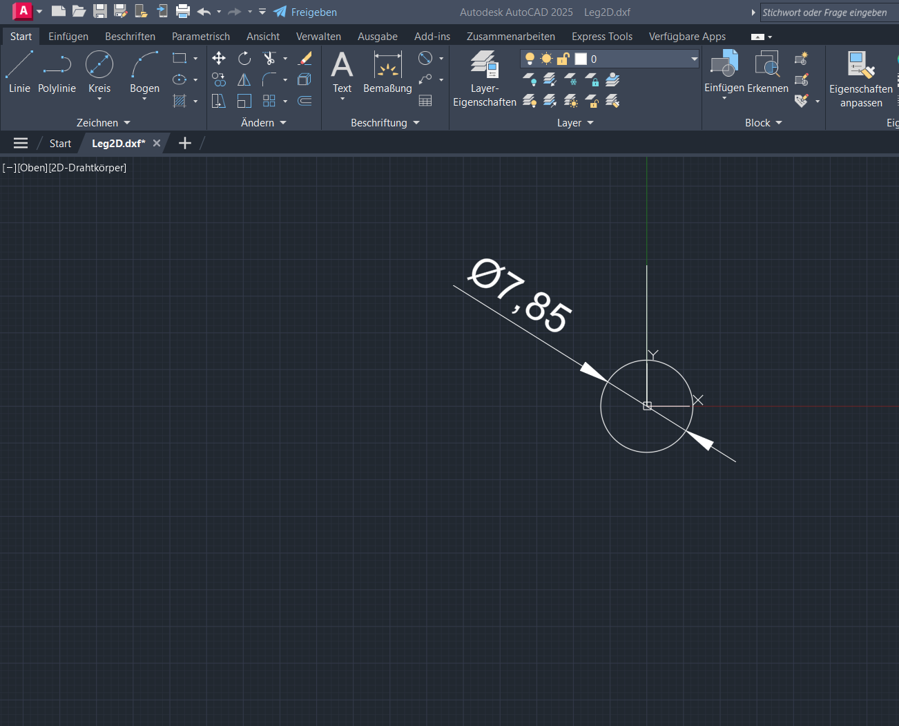
I started by drawing a circle with a
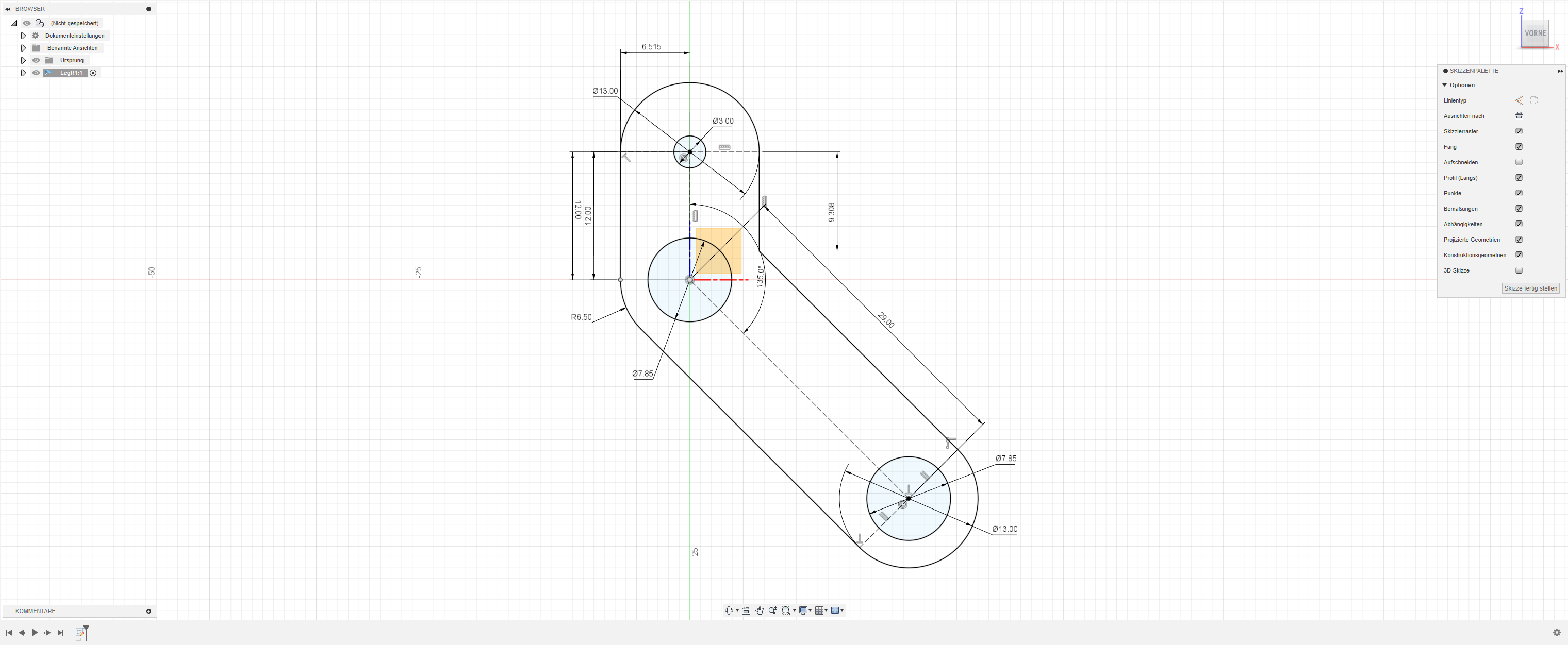
Step 1: Drawing the Initial Circle
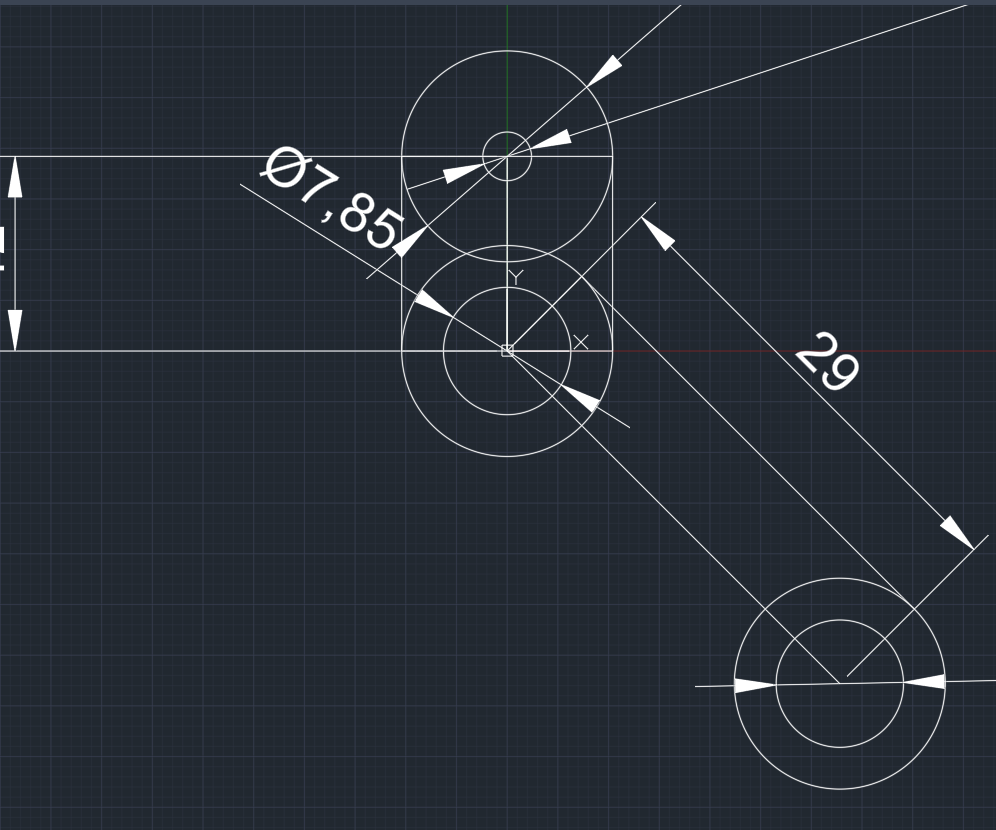
I started by drawing a circle with a diameter of 7.85 mm using the circle feature. This circle represents one
of the mounting holes for the leg.
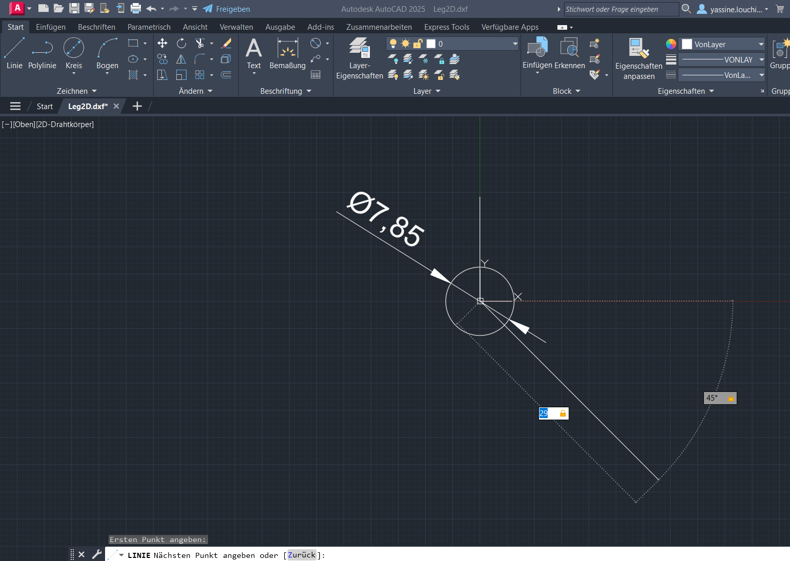
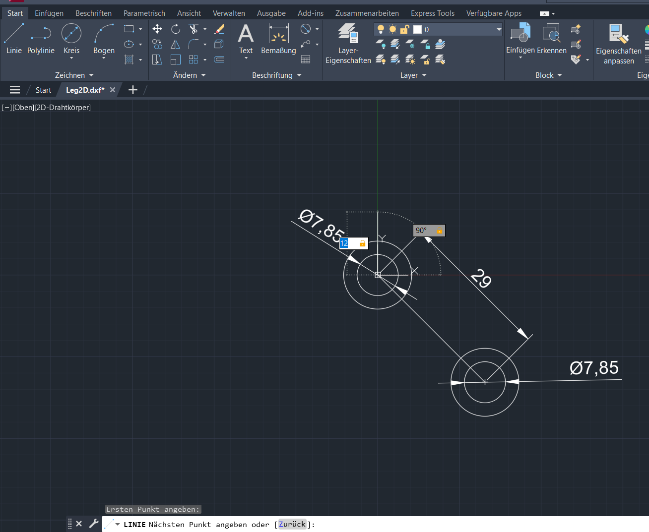
Step 2: Creating an Angled Line
Next, I created a line that is 29 mm long and positioned it at a 45° angle from the x-axis originating from the
center of the first circle. This line helps in aligning the next feature.
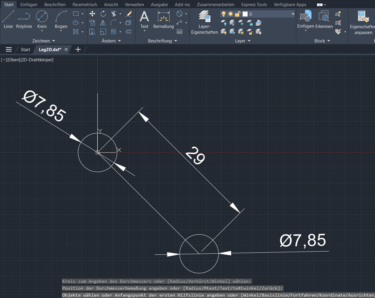
Step 3: Drawing a Second Circle
At the end of the angled line, I drew another circle identical to the first one, with a diameter of 7.85 mm,
using the same circle feature. This creates the second mounting hole.
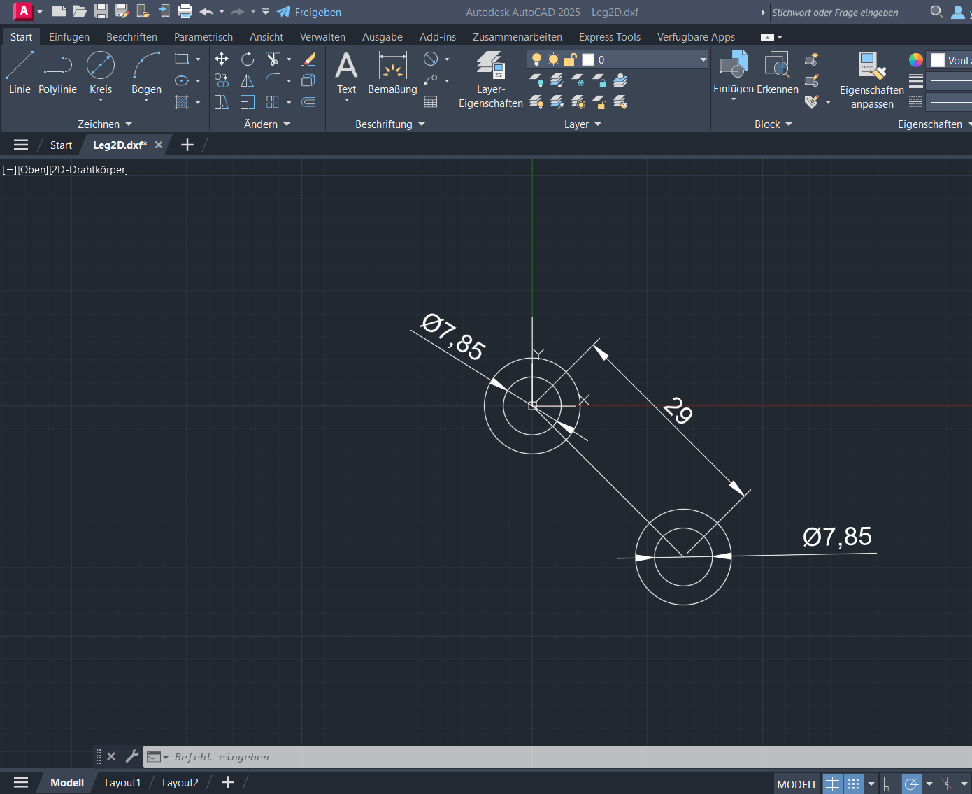
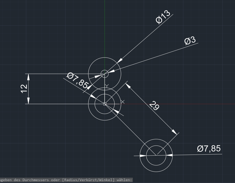
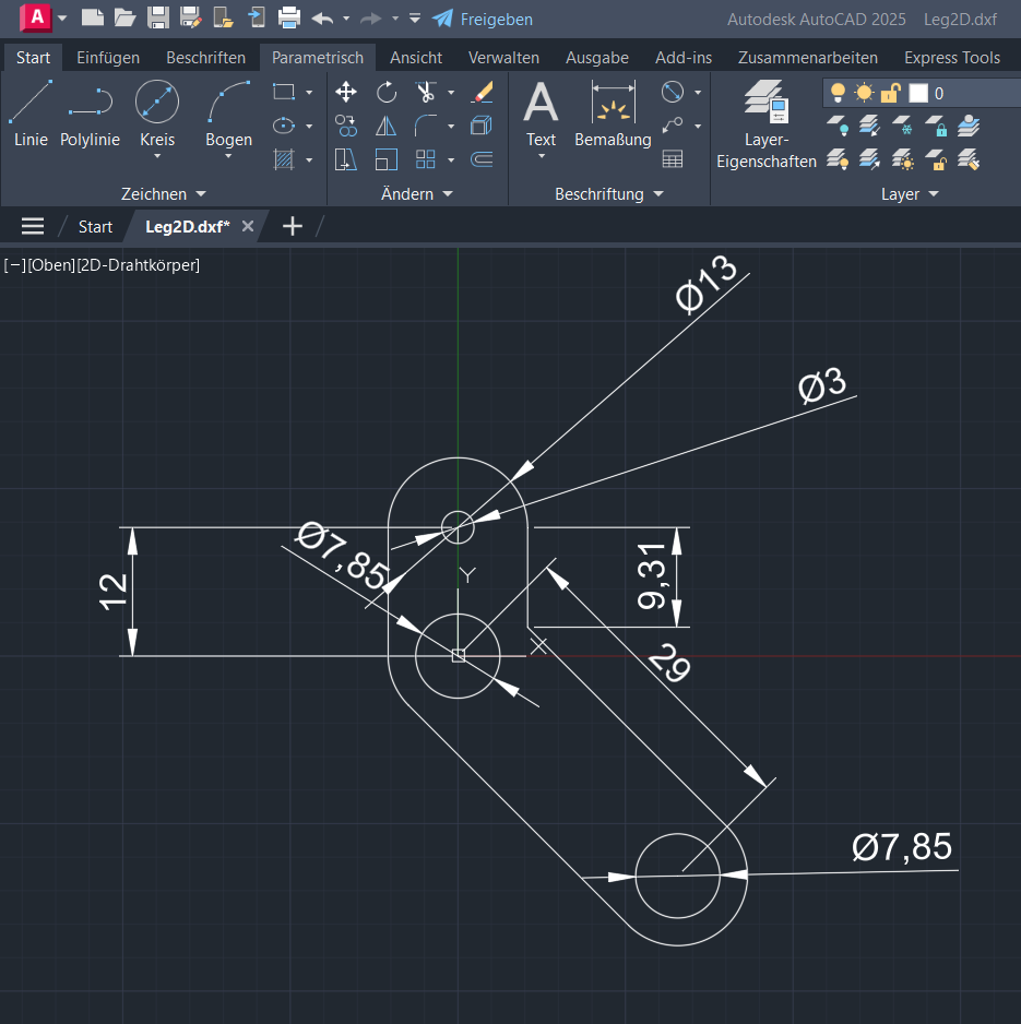
Step 4: Adding Larger Circles
From the center of each 7.85 mm circle, I drew larger circles with a diameter of 13 mm. These larger circles
help define the main body of the leg.
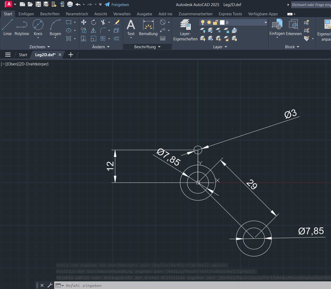
Step 5: Drawing a Vertical Line
Next, I drew a vertical line that is 12 mm long from the center of the lower circle. This line is collinear
with the y-axis and will help in positioning the top circle.
Step 6: Adding a Small Top Circle
At the top end of the 12 mm line, I drew a small circle with a diameter of 3 mm. This circle represents another
mounting or pivot point.
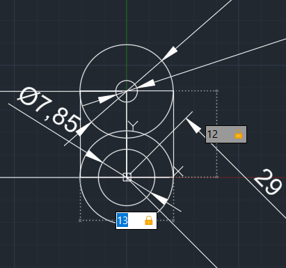
Step 7: Adding a Larger Top Circle
Centered on the 3 mm circle, I drew a larger circle with a diameter of 13 mm, similar to the ones drawn
earlier. This forms the top part of the leg structure.
Step 8: Connecting Circles with Tangential Lines
I connected the larger top circle to the middle circle using tangential lines. This creates smooth transitions
between the circles, defining the shape of the leg.
Step 9: Connecting Middle and Bottom Circles
Similarly, I connected the middle circle to the bottom circle with tangential lines. This ensures that the
structure is continuous and maintains its integrity.

Step 10: Trimming Unwanted Lines
Finally, I trimmed the unwanted lines and shapes that were no longer needed to complete the design. This
resulted in the final leg shape, ready for use in the robot assembly.
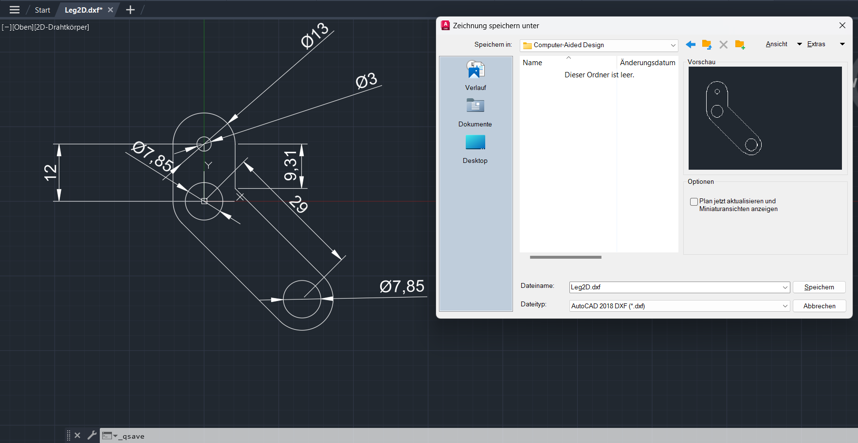
Original design files:
Please find the link below to access the comprehensive set of design
files for your reference and review.
Download files created with AutoCad2D
Download files created with Fusion360