6. Electronics Design
assignment assignment assignment group project: use the test equipment in your lab to observe the operation of a microcontroller circuit board individual project: design a development board to interact and communicate with an embedded microcontroller extra credit: try another design workflow extra credit: make a case for it extra credit: simulate its operationindividual assignment
For larger microcontroller projects I think I will use commercially available development boards.
Currently, the only projects for which I would build a development board myself are boards where even a Digispark board is too big.
So for this week I decided to design a very small, simple and universal development board to which other electronics can be easily connected.
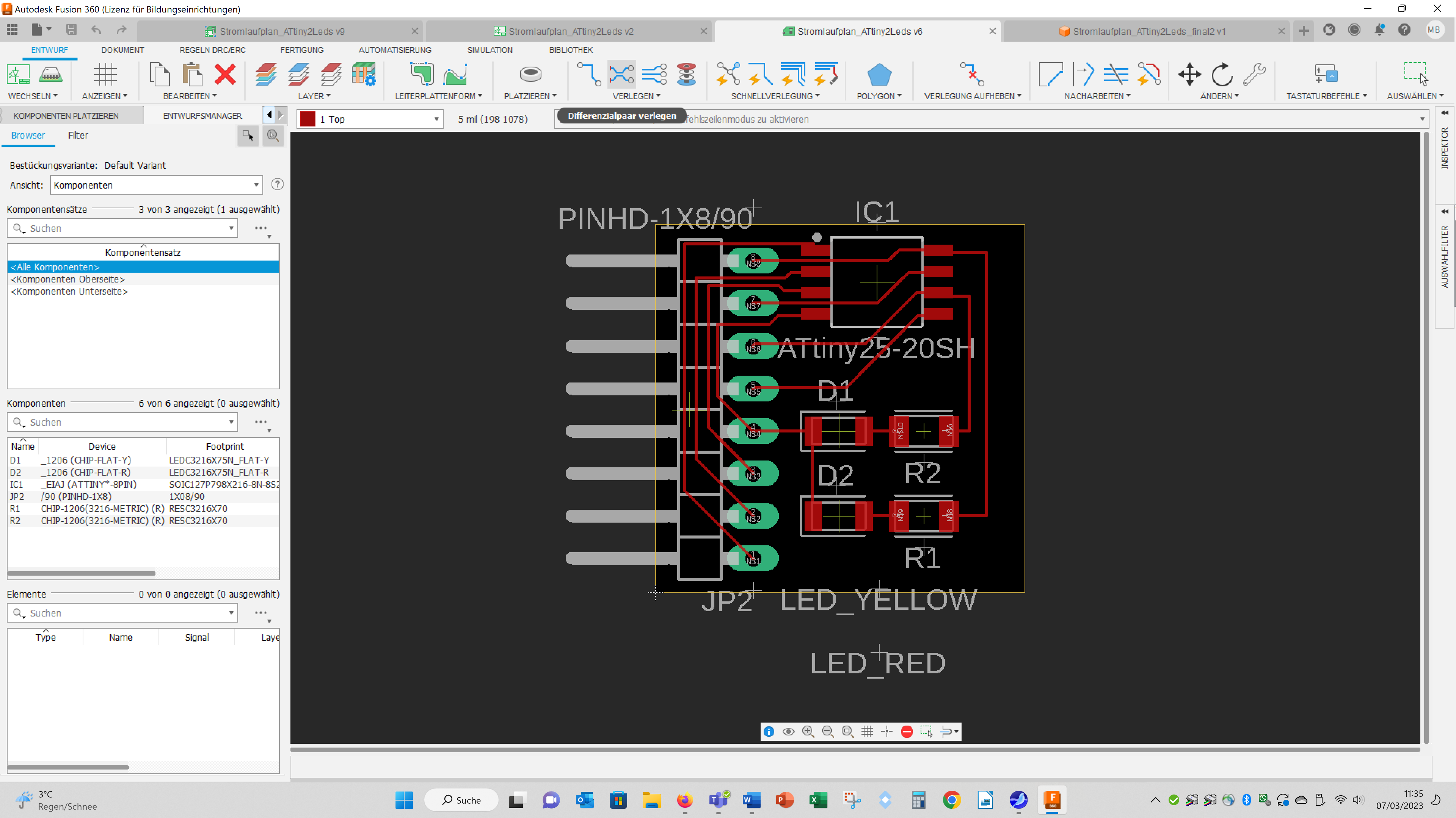
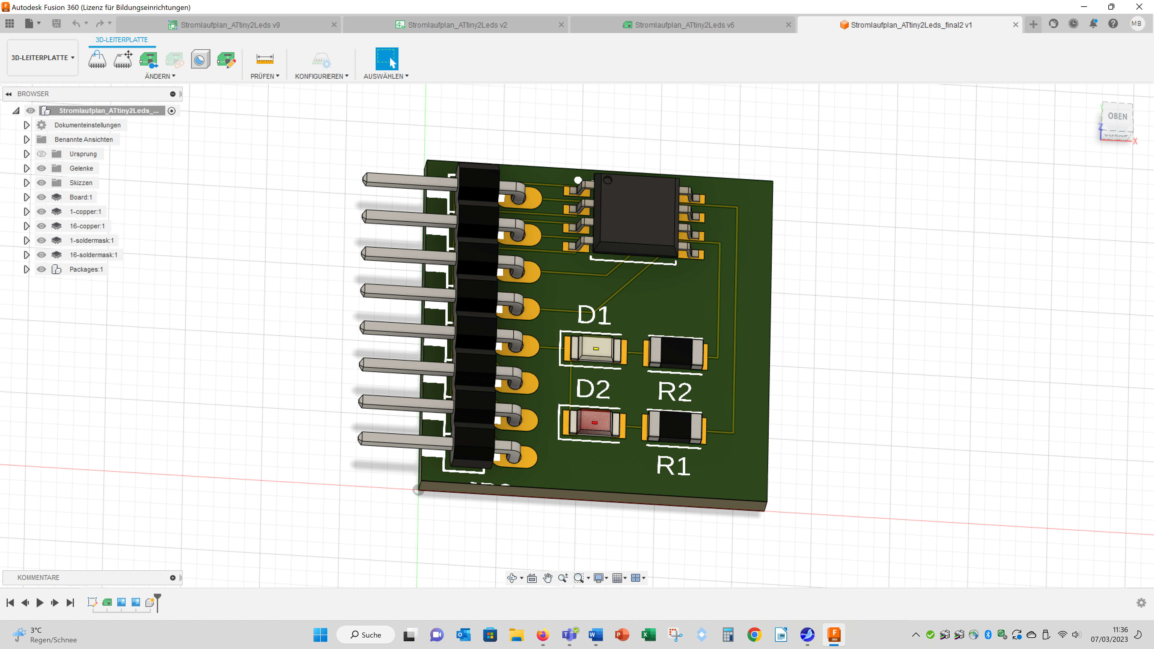
For this purpose I connected an ATtiny85-su with a power and a traffic led and connectors in Fusion 360:
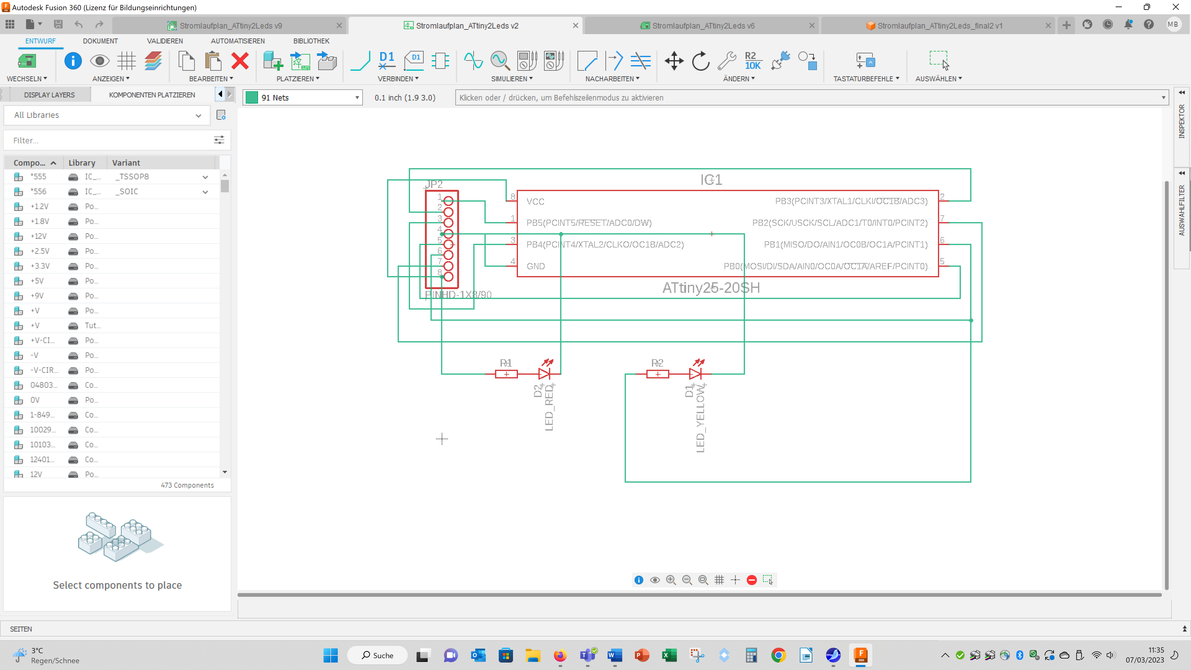
The ATtiny85 I included in the variant: EIAJ.
The resistors and the leds have the sizes: 1206.
The connecor is called: PINHD-1x8.
This is a through hole connector, but I hope I can tell the mill to ignore the holes.
Here you find a good explanation how to design pcbs in Fusion 360 (the video is in German): https://www.youtube.com/watch?v=L1YDiBZfoO8&t=346s
Here you can download the board file:
group assignmentwe decided to analyse the PWM-signal and the signal you get using the tone() funcion of an Arduino.
I wondered if a second Arduino could be used for this purpose.
For comparison purposes, we compared the signals with an Arduino and an oscilloscope.
On the first Arduino we used a potentimeter to change the PWM signal or the frequency of the tone() function.
To generate and vary the PWM signal we used the example sketch "AnalogInOutSerial".
For the tone() function we used the example sketch "TonePitchFollower" and adapted the map function as follows: map(sensorReading, 0, 1023, 35, 1500).
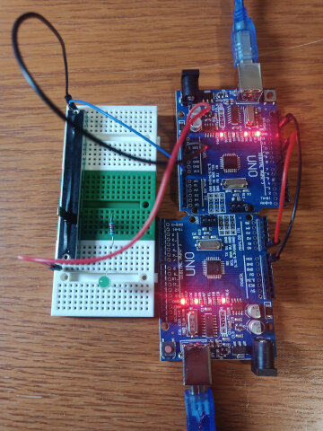
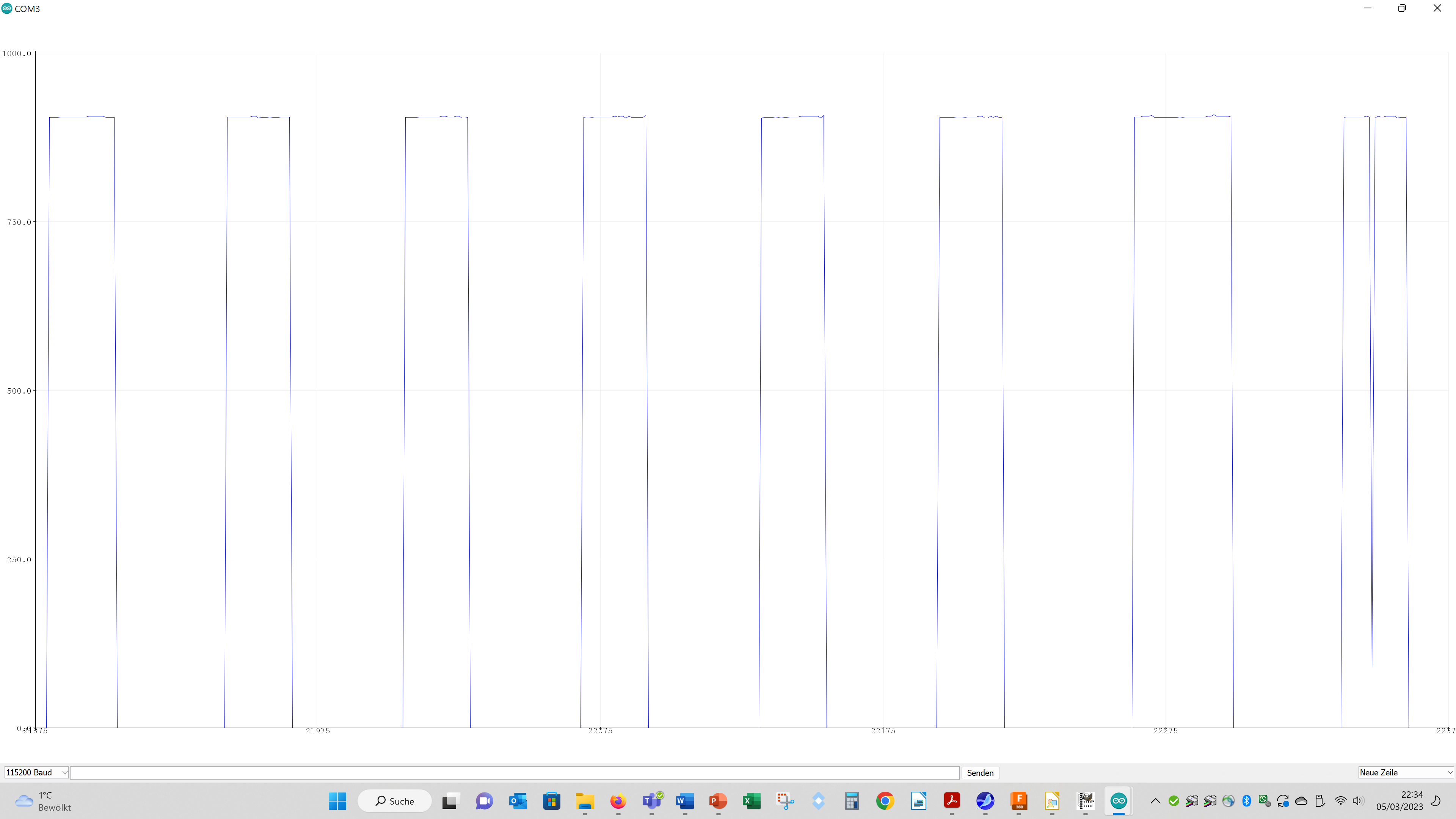
First I tested with a led and a loudspeaker and the serial monitor whether the desired signals are generated. Then I read out the signals with a second Arduino.
Therefor, I load the "AnalogReadSerial" example sketch on the second Arduino with the changes that the baud rate was changed to 115200 and the delay was removed.
The signals from the first Arduino were connected to Pin A0 and each one ground pins of both Arduinos were connected.
Maybe it is also beneficial to add a pull down resistor to Pin A0.
I had the signals output via the serial plotter.
For the tests with the oszilloskope the signals were conneted to the prope tip and the ground of the prope tip was connected to the ground of the Arduino.
Setup for the PWM signal:
Setup for the tone() signal:
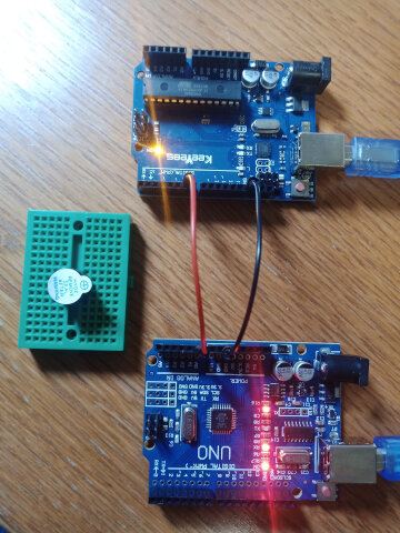
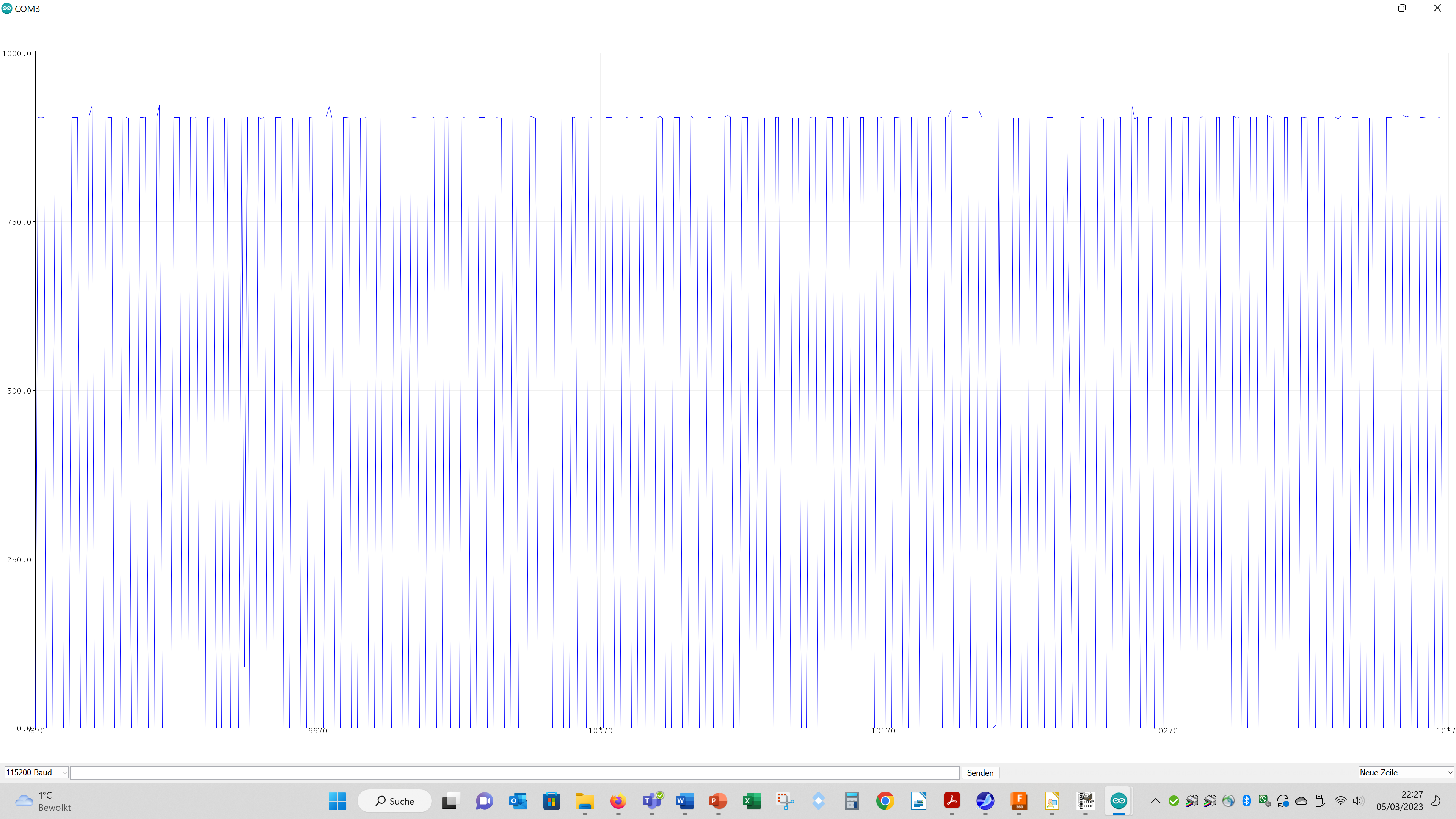
Here you see the results of using the Arduino as an oszilloskope:PWM min:
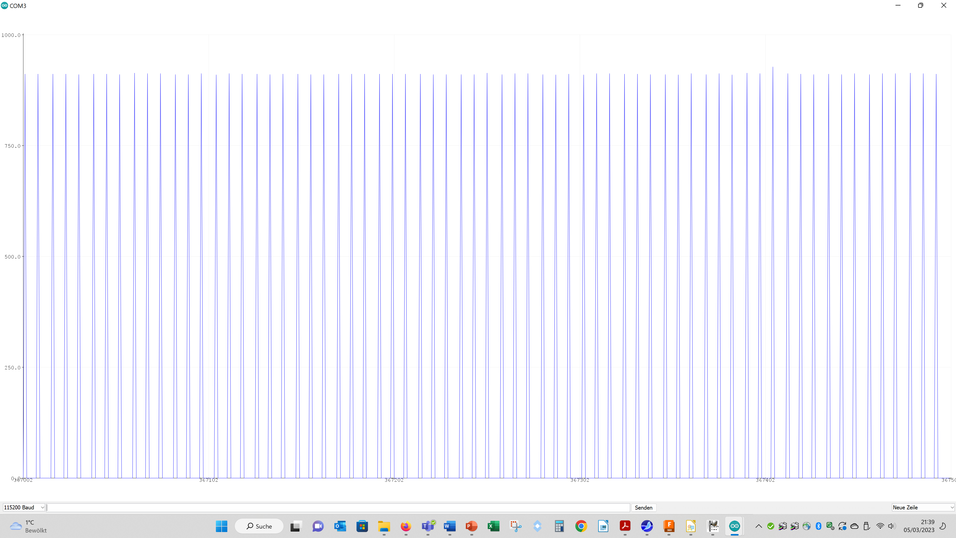
PWM max:
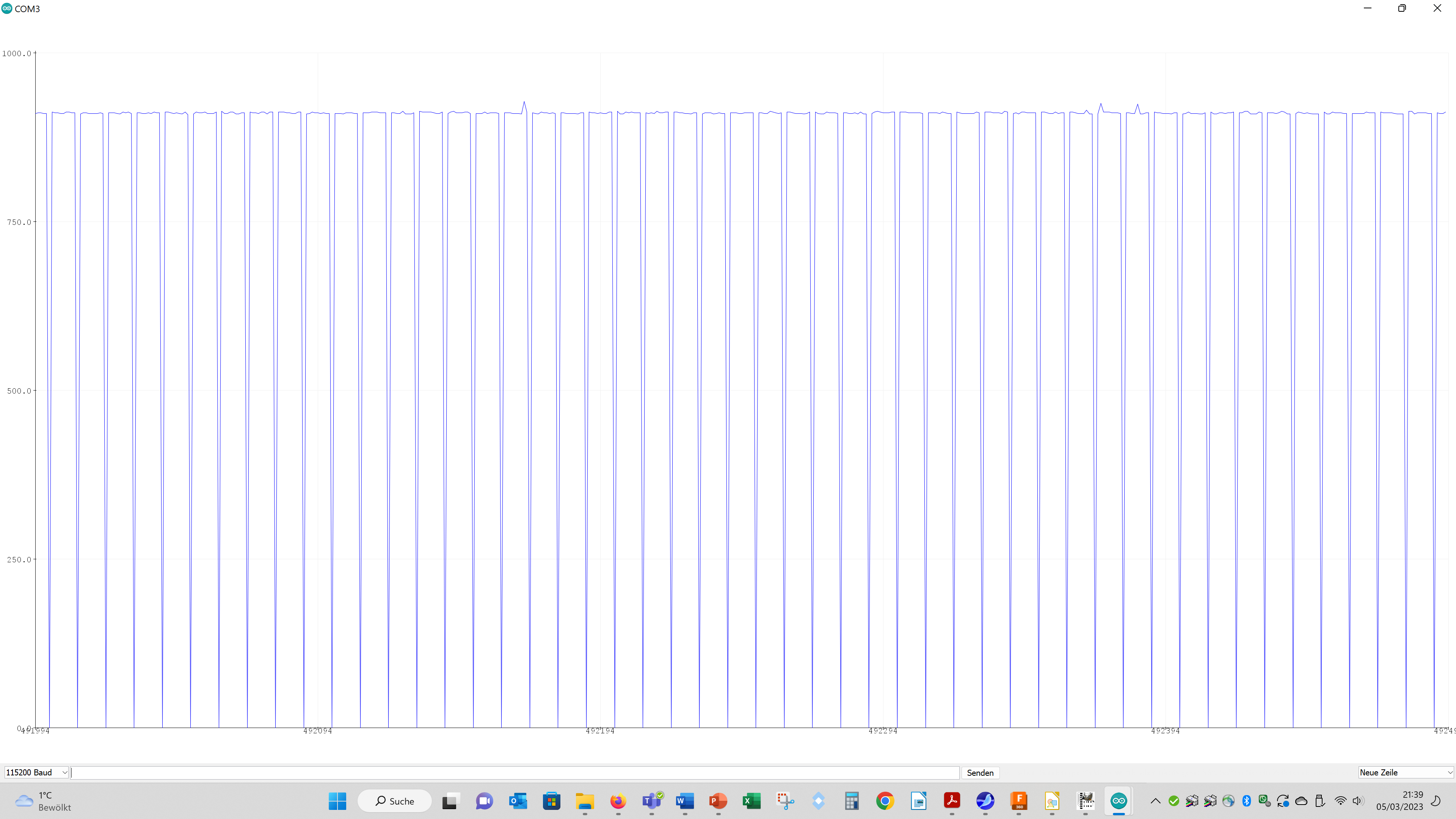
tone 50 Hz:
tone 200 Hz:
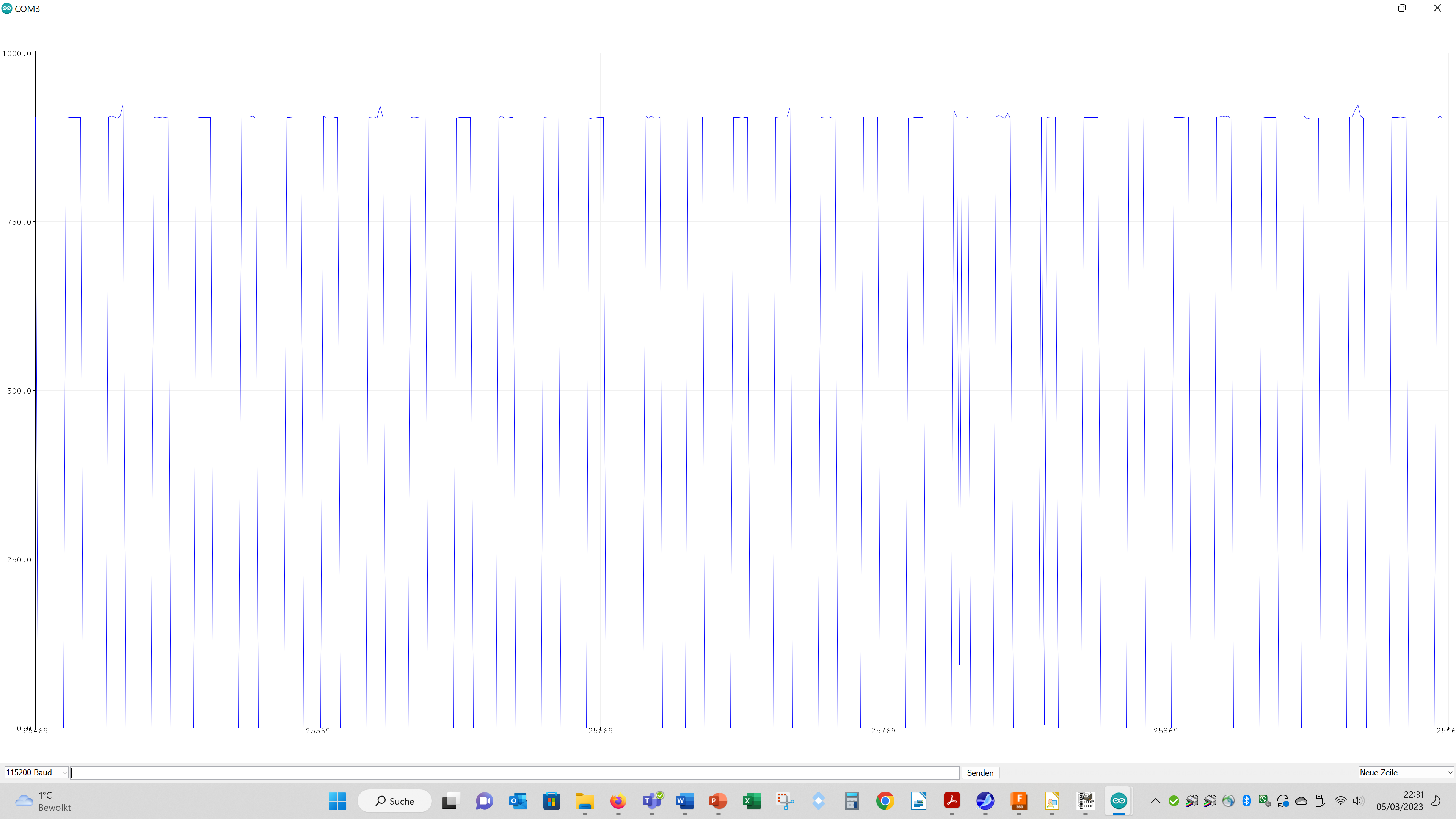
tone 500 Hz:
Here you see the results using an oszilloskope:
for changing the PWM signal and for changing the tone () frequency:
Summing up: for simple purposes you can use an Arduino as an oszilloscope!