4. Embedded Programming
individual assignment:
browse through the data sheet for your microcontroller
program a microcontroller development board
to interact (with local input &/or output) and communicate (remotely)
extra credit: use different languages &/or development environments
group assignment:
compare the performance and development workflows for other architectures
individual assignment
I was somehow overwhelmed by the nearly 1000 pages long datasheets of actual microcontrollers, so I decided to read the datasheet of an ATtiny85. The full version of this datasheet still has 234 pages, but I found a summary of the datasheet with only 30 pages. So I read this summary completely and then screened through the full version. After that, I also read a summary data sheet for the RP2040 and screened though its full datasheet.
Datasheet ATtiny85-20PU/SU
You can download the datasheets from:
Summary
https://cdn-reichelt.de/documents/datenblatt/A300/ATTINY25-ATTINY45-ATTINY85_DATASHEET.pdf
Full Version
Here the most interesting facts:
- Atmel 8-bit AVR Microcontroller
- 8 Legs/Pins
- 8 KB in-system programmable flash memory (6 KB free to use)
- 516 byte SRAM
- 2 PWM channels
- 10-bit Analog Digital Converter
- interrups
- capacitive touch sensing – with Atmel QTouch library – see QTouch Library User Guide
- internal pull-up resistors
- SPI serial interface
- Power-down modes
- 6 programmable I/O pins
- operating voltage: 2.7 – 5.5 V
- up to 20 MHz @ 4.5 – 5.5 V
- most important Pin functions:
1: Pin 5, Reset -> when connected to ground, (pin left from the half circle on the microcontroller)
2: Pin 3
3: Pin 4
4: GND
5: Pin 0, MOSI (Master out, Slave in)
6: Pin 1, MISO (Master in, Slave out)
7: Pin 2, SCK (Serial Clock)
8: VCC = 5V
Datasheet RP2040
You can download the datasheets from:
Summary
https://datasheets.raspberrypi.com/rp2040/rp2040-product-brief.pdf
Full Version
https://datasheets.raspberrypi.com/rp2040/rp2040-datasheet.pdf
You can have a very impressive view in the interior of the chip here:
https://en.wikipedia.org/wiki/RP2040#/media/File:Raspberry-pi_rp2-b0_s1-9_mit20x.jpg
Here some of the most interesting differences to the ATtiny85:
- Dual ARM Cortex-M0+ @ 133 MHz
- 32 bit
- 2 MB flash memory
- 264 kB on-chip SRAM memory
- 30 GPIO pins
- 4 analogue inputs
- 2 × UARTs
- 2 × SPI controllers
- 2 × I2C controllers
- 16 × PWM channels
program a microcontroller development board
For the second part of the individual assignment I attached a led and a photodetector amplifier (tsl257-lf) on a bread board to an Arduino nano. The led was directly oriented towards the photodetector. Then I wrote a code based on the Fade- and the ReadAnalogVoltage-code example from Arduino to change the brightness of the led and to read the brightness by the photodetector and to plot both in the serial monitor. The photodetector is veeery sensitive, so I only could measure the difference between led on and led off even with the lowest brightness of the led. The lowest value of the photodetector in voltage war 2.06 volt, because I could not cover the set up completely and because of the led on the Arduino.
Results plotted in the serial monitor:
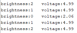
Left: brightness of the led (0 off, 255 highest brightness), Right: measured brightness in voltage.
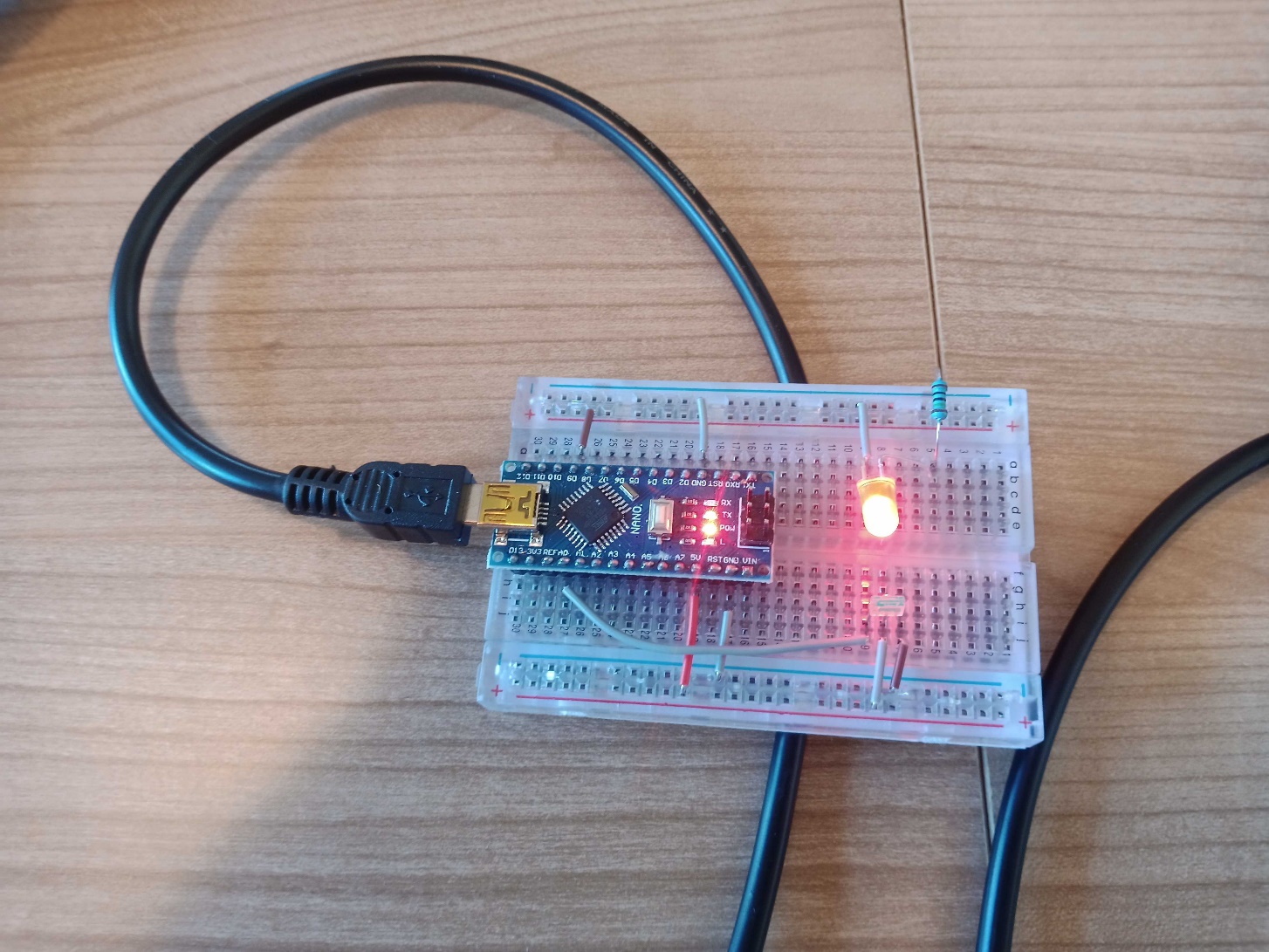
set up
Code
/*
Code based on the example codes “Fade” and “ReadAnalogVoltage” to read the brightness of a led with a tsl257-lf photodetector amplifier.
*/
int led = 9; // the PWM pin the LED is attached to
int brightness = 0; // how bright the LED is
int fadeAmount = 1; // how many points to fade the LED by (original: 5)
// the setup routine runs once when you press reset:
void setup() {
// initialize serial communication at 9600 bits per second:
Serial.begin(9600);
pinMode(led, OUTPUT);
}
// the loop routine runs over and over again forever:
void loop() {
// set the brightness of pin 9:
analogWrite(led, brightness);
Serial.print("brightness:");
Serial.print(brightness);
Serial.print(" ");
// change the brightness for next time through the loop:
brightness = brightness + fadeAmount;
// reverse the direction of the fading at the ends of the fade:
if (brightness <= 0 || brightness >= 10) { // (original: >= 255)
fadeAmount = -fadeAmount;
}
// wait for 30 milliseconds to see the dimming effect
delay(300);
// read the input on analog pin 0:
int sensorValue = analogRead(A0);
// Convert the analog reading (which goes from 0 - 1023) to a voltage (0 - 5V):
float voltage = sensorValue * (5.0 / 1023.0);
// print out the value you read:
Serial.print("voltage:");
Serial.println(voltage);
Here you can download the Arduino file:
ReadAnalogVoltage_and_Fade_max10
group assignment
To compare the performance of different microcontrollers we run two different performance tests. We used the performance tests Dhrystone and Coremark:
Here you find a video with further information:
Benchmark: Dhrystone
I downloaded the Dhrystone benchmark for Arduino microcontrollers from this website:
https://github.com/ghalfacree/Arduino-Sketches/tree/master/Dhrystone/dhry21a
you have to copy and paste the Arduino file (.ino) in an empty Arduino sketch and save it.
Then you have to copy and paste the library (.h) in an empty editor sketch and save it as dhry.h in the same folder as the Arduino file.
Or you can click on the file with the right mouse button and choose “Ziel speichern unter” (engl.: “save target as”).
The .ino and the .h file have to be in the same folder.
The results of the tests were given in the serial monitor.
For the Dhrystone test the MIPS rating is crucial.
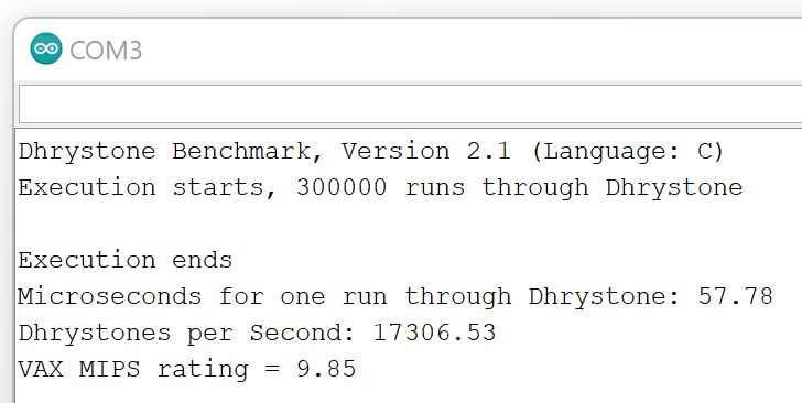
Arduino Nano (ATmega328)
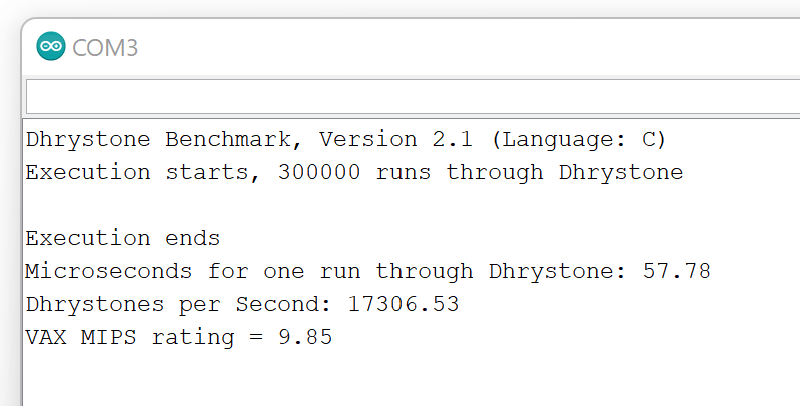
MIPS (Millions of instructions per second): 9.85
MIPS: 9.85
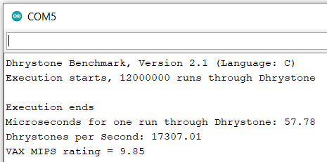
Its seems there is no difference in the results using 12.000.000 runs and a baudrate of 115.200 (see below). But using 12 Mio runs the test last much longer.
Arduino Mega (ATmega2560)
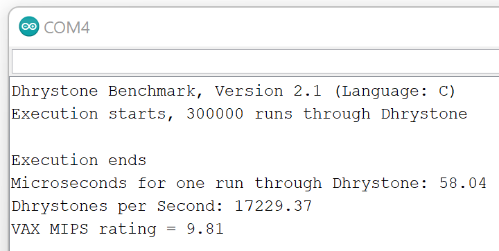
MIPS: 9.81
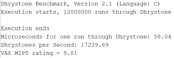
MIPS: 9.81
Its seems there is no difference in the results using 12.000.000 runs and a baudrate of 115.200 (see below). But using 12 Mio runs the test last much longer.
Arduino Uno (ATmega328P)
MIPS: 9.85 (the Arduino Uno has (nearly) the same microcontroller as the Arduino Nano)
Digispark (ATtiny85)
To use it with the Arduino IDE you have to paste the following line in: Datei – Voreinstellungen – Zusätzliche Boardverwalter-URLs:
https://raw.githubusercontent.com/digistump/arduino-boards-index/master/package_digistump_index.json
and install Digistump ARV Boards by Digistump in the Boardverwalter
Then choose: Board - Digistump AVR Boards – Digispark (Default 16,5 MHz)
To upload the code do not connect the Digispark to your computer, but first press the upload button. Then you were prompted to connect it.
Error message during upload: “no match for 'operator!' (operand type is 'TinyDebugSerial')”
Raspberry Pi Pico (RP2040)
To use the Raspberry Pi Pico with the Arduino IDE you have to search in the Boardverwalter for “pico” and install both driver: Arduino Mbed OS RP2040 Boards and Arduino Mbed OS Boards.
Select the pico under Arduino Mbed OS Boards. During connecting the pico to your computer you have to press the white button on the pico.
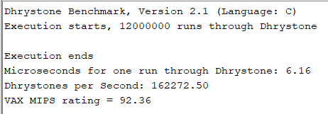
MIPS: 92.36
ESP32
To use the Esp32 with the Arduino IDE you have to paste the following line in: Datei – Voreinstellungen – Zusätzliche Boardverwalter-URLs:
https://dl.espressif.com/dl/package_esp32_index.json
Then search in the Boardverwalter for esp32 and install:
Esp32 by Espressive Systems
Choose the board: ESP32 Arduino – ESP32 Dev Module
for further infos see:
https://www.youtube.com/watch?v=IYUBCgW_GoQ&t=29&ab_channel=PrototypingforMaker
I changed the baudrate to 115200 (under Werkzeuge – Uploadspeed and in the code).
After uploading I go this message in the serial monitor:
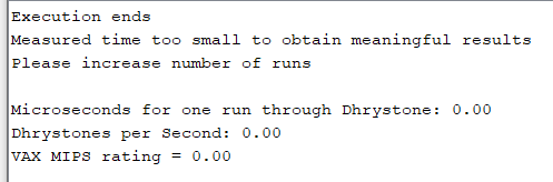
So I changed the number of runs from:
Number_Of_Runs = 300000;
to:
Number_Of_Runs = 12000000;
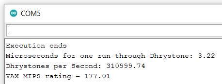
MIPS: 177.01
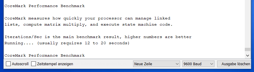
Benchmark: Coremark
You can download the Coremark benchmark here by pressing: Code – Download Zip:
https://github.com/PaulStoffregen/CoreMark
after downloading, unzipping and creating a folder for the .ino file you have to move all files in the folder of the .ino file.
For the Coremark test the Iterations/Sec rating is crucial.
Arduino Nano (ATmega328)
With the Arduino nano the sketch did not come to an end…
Arduino Mega (ATmega2560)
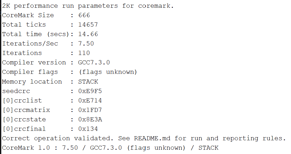
Iterations per second: 7.5
Arduino Uno (ATmega328P)
With the Arduino Uno the sketch did not come to an end, too.
Raspberry Pi Pico (RP2040)
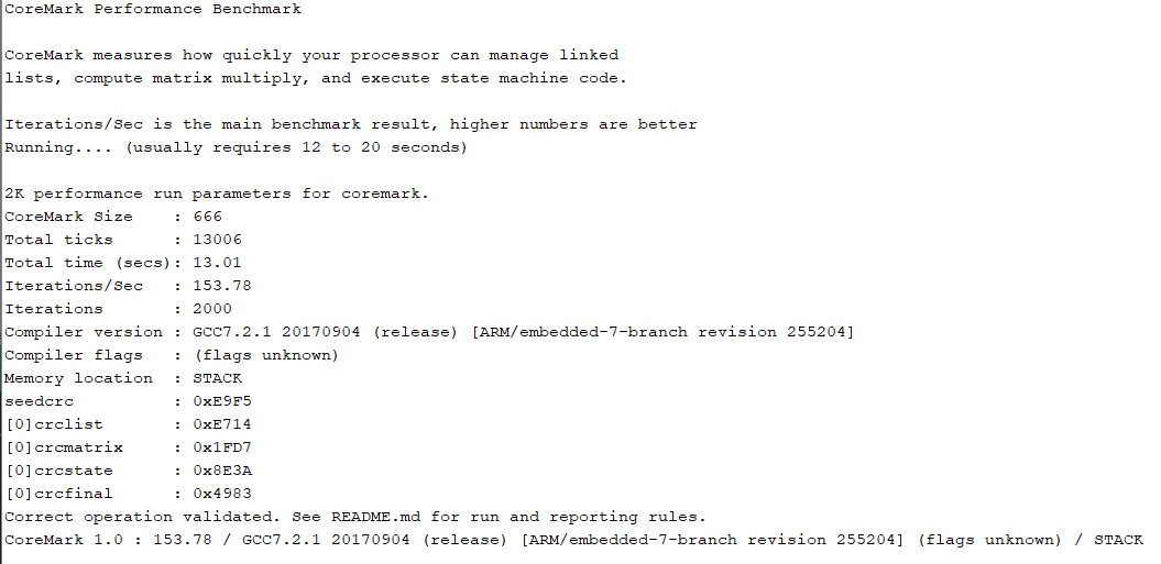
Iterations per second: 153.78
ESP32
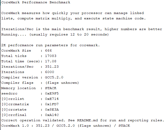
Iterations per second: 351.23
Summary
According to both benchmark tests the ESP32 is the fasted microcontroller of all microcontroller we tested.