Networking and Communications
Group Assignment
Link to the group assignment: BOYS GROUP FAB23
Learning from Group Work
From the group work I learned about RFID Reader which is Radio-frequency identification. It uses electromagnetic fields to automatically identify and track tags attached to objects. An RFID system consists of a tiny radio transponder, a radio receiver and transmitter. We have tested RFID reader in Arduino and it worked.
Individual Assignment
At first I was lost because this week completely looked new and it was hard for me to understand. However, Ms. Zina and Mr. Rico explained on the importance of networking and communications with our PCB board. Therefore, I had my PCB with ATtiny1614 MCU and thought of using ESP32C3 for my final board considering its features like WiFi and Bluetooth connectivity. If in case I wanted to expand my project in future, I can easily incorporate them as and when required. With ESP32 I can connect with the app in phone to control my board. But for this week I planned to use blynk app in the phone to control the LED of my ATtiny MCU board.
Connecting Blynk App from mobile to my board
I wanted to use blynk app from my phone to control the LED of my board which had ATtiny 1614 MCU. However, I had no idea how it has to be done and then I tried getting idea from youtube YouTube Video. After watching this video, I tried to figure out how possibly can I make my board be controlled with Blynk App. This video talked about using ESP32 which my board was missing. Then I asked help from Mr. Thinley Jamtsho of JNWSFL who was at his best with IoT and I thank him for the assistance provided.
Processes (Work FLows)
I downloaded Blynk App from App store on my phone.
This time, I first started by debugging before really trying to work on my board. That is Mr. Thinley told me that we could try to connect Arduino Mega in combination with ESP32 with Blynk App from my phone to see if that works.
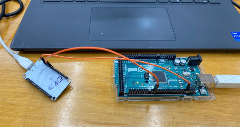
Connected one GND of Arduino with GND of ESP32 module and then RX pin from ESP32 with Rx of Arduino.
Then I got the code examples from CODE Examples for BLynk App with WiFI.. There were codes for Bluetooth, WiFi, USB ethernet etc but I wanted to test with WiFi so I chose the following example.
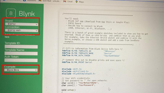
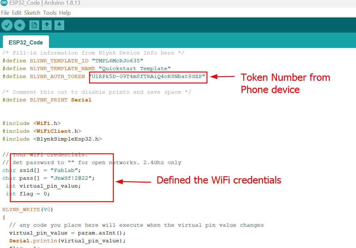
In this code examples you had to define Auth Token which is in the Blynk App device and set WiFi credentials which your phone and computer is connected as shown below.
Codes for Testing
 /* Fill-in information from Blynk Device Info here */
            #define BLYNK_TEMPLATE_ID "TMPL6McRJo635"
            #define BLYNK_TEMPLATE_NAME "Quickstart Template"
            #define BLYNK_AUTH_TOKEN "UlRPk5D-09T4m8fTRAiQ4oR8Nbat8GZP"

            /* Comment this out to disable prints and save space */
            #define BLYNK_PRINT Serial


            #include
            #include
            #include

            // Your WiFi credentials.
            // Set password to "" for open networks. 2.4Ghz only
            char ssid[] = "Fablab";
            char pass[] = "JnwSf!2@22";
             int virtual_pin_value;
             int flag = 0;

            BLYNK_WRITE(V0)
            {
              // any code you place here will execute when the virtual pin value changes
              virtual_pin_value = param.asInt();
              Serial.println(virtual_pin_value);
              flag = 1;
            }

            void setup()
            {
              // Debug console
              Serial.begin(115200);
              Serial2.begin(9600);

              Blynk.begin(BLYNK_AUTH_TOKEN, ssid, pass);
              // You can also specify server:
              //Blynk.begin(BLYNK_AUTH_TOKEN, ssid, pass, "blynk.cloud", 80);
              //Blynk.begin(BLYNK_AUTH_TOKEN, ssid, pass, IPAddress(192,168,1,100), 8080);
            }

            void loop()
            {
              Blynk.run();
              if(virtual_pin_value == 1 && flag == 1)
              {
                Serial2.write(0x41);// You can inject your own code or combine it with other sketches.
                flag = 0;
                Serial.println("0x41");
              }
               if(virtual_pin_value == 0 && flag == 1)
              {
                Serial2.write(0x42);
                Serial.println("0x42");
                flag = 0;// You can inject your own code or combine it with other sketches.
              }
              // Check other examples on how to communicate with Blynk. Remember
              // to avoid delay() function!
            }
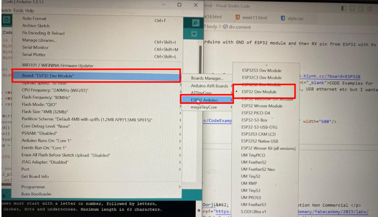
Board selection: I used ESP32 Dev Module as shown below by going to tools and then board manager. I had ESP32 board installed on Arduino IDE.
Then selected the port COM5 and Programmer is ESPtool. Verified and Uploaded the code. Then whenever I pressed on "ON" and "OFF" on my phone the digit 41 and 42 read on serial monitor. Which means I have successfully connected Bylnk App on my phone to control LED on board. The type of connection I made is wireless which is why WiFi connection was required.
The video below explains about successfully connecting Blynk App to Arduino board.
Blynk App with My Board (ATtiny 1614)
I made the connection. Meaning I used ESP32 along with my ATtiny board. ESP32 module is used because ATtiny 1614 has no WiFi features so to connect Blynk App to my board required WiFi connection. Connected GND from ESP to GND of my board and TXD from ESP32 to RXD pin of my Board. The image is shown below.
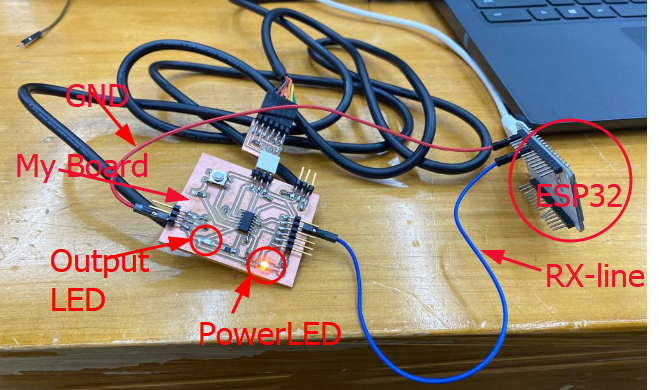
Regarding the coding, I had to do it for two. One is for my board and one for ESP32 module to connect Blynk App from my phone to my board. Here, ESP32 is used to assist my board to get connected with my phone App.
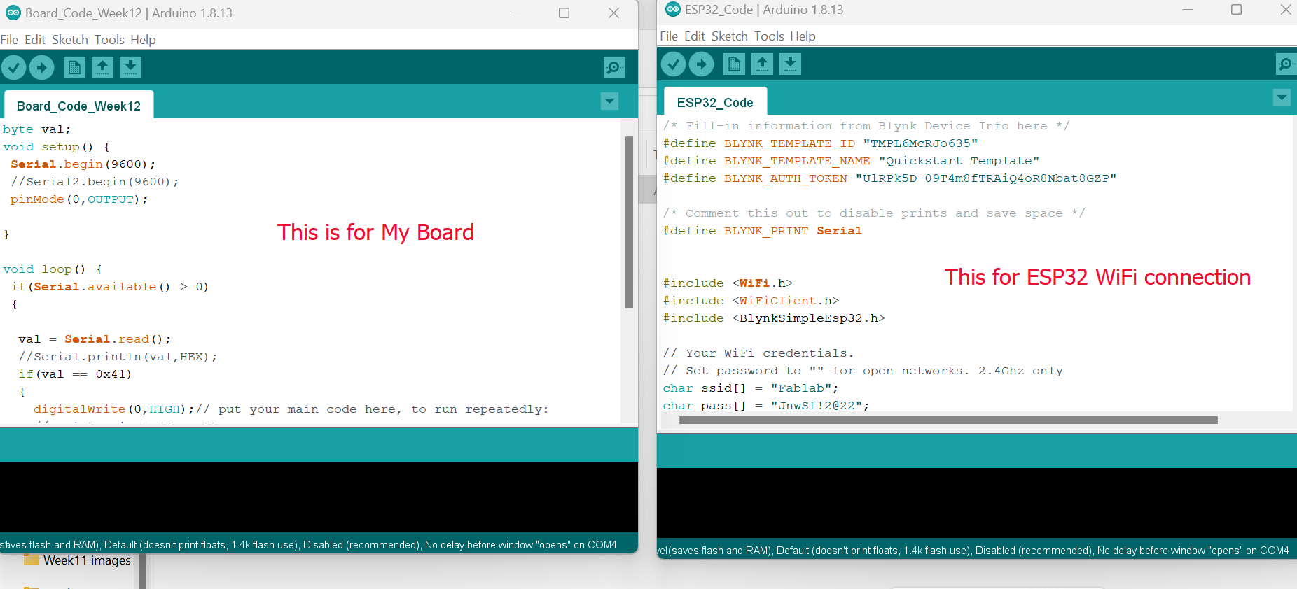
The Code for Board ATtiny1614
byte val;
            void setup() {
             Serial.begin(9600);
             //Serial2.begin(9600);
             pinMode(0,OUTPUT);

            }

            void loop() {
             if(Serial.available() > 0)
             {

              val = Serial.read();
              //Serial.println(val,HEX);
              if(val == 0x41)
              {
                digitalWrite(0,HIGH);// put your main code here, to run repeatedly:
                //Serial.println("HIGH");
              }
              if(val == 0x42)
              {
                digitalWrite(0,LOW);
                //Serial.println("LOW");
              }
             }

            }
The Code for ESP32
/* Fill-in information from Blynk Device Info here */
              #define BLYNK_TEMPLATE_ID "TMPL6McRJo635"
              #define BLYNK_TEMPLATE_NAME "Quickstart Template"
              #define BLYNK_AUTH_TOKEN "UlRPk5D-09T4m8fTRAiQ4oR8Nbat8GZP"

              /* Comment this out to disable prints and save space */
              #define BLYNK_PRINT Serial


              #include
              #include
              #include

              // Your WiFi credentials.
              // Set password to "" for open networks. 2.4Ghz only
              char ssid[] = "Fablab";
              char pass[] = "JnwSf!2@22";
               int virtual_pin_value;
               int flag = 0;

              BLYNK_WRITE(V0)
              {
                // any code you place here will execute when the virtual pin value changes
                virtual_pin_value = param.asInt();
                Serial.println(virtual_pin_value);
                flag = 1;
              }

              void setup()
              {
                // Debug console
                Serial.begin(115200);
                Serial2.begin(9600);

                Blynk.begin(BLYNK_AUTH_TOKEN, ssid, pass);
                // You can also specify server:
                //Blynk.begin(BLYNK_AUTH_TOKEN, ssid, pass, "blynk.cloud", 80);
                //Blynk.begin(BLYNK_AUTH_TOKEN, ssid, pass, IPAddress(192,168,1,100), 8080);
              }

              void loop()
              {
                Blynk.run();
                if(virtual_pin_value == 1 && flag == 1)
                {
                  Serial2.write(0x41);// You can inject your own code or combine it with other sketches.
                  flag = 0;
                  Serial.println("0x41");
                }
                 if(virtual_pin_value == 0 && flag == 1)
                {
                  Serial2.write(0x42);
                  Serial.println("0x42");
                  flag = 0;// You can inject your own code or combine it with other sketches.
                }
                // Check other examples on how to communicate with Blynk. Remember
                // to avoid delay() function!
              }
After coding, as usual I had to choose board from board manager and I chose ATtiny 1614 board under megaTinyCore>> Port COM4>>Serial UPDI-SLOW:57600 baud programmer. Selected port COM5 to power ESP32 module. Verify and Upload code and then controlled output LED from Blynk App.
The video below demonstrates the working of my baord with Blynk App. And it is also the hero shot of the week.
I did not have to design new board for networking week as well. I had my board fabricated from earlier weeks assignments and it worked with blynk app as well.
Design Files
Code for ESP32 and ATtiny1614
ATtiny1614