Input Devices
Group Assignment
We connected input devices to an arduino for the week and tried with two different input devices. Also we tried with our own board apart from trying in arduino board. I assisted team with taking photos and connecting the wires to Oscilloscope to detect or analyze the signals. It has been a week with lot of fun and exciting experiments conducted with every individuals board.
Individual Assignment
This week was about input devices and I was told to test connecting any input device to my board which I had milled and soldered from the electronic production week. Therefore, I decided to test by connecting to PIR(Passive Infrared) which detects infrared that is radiated from all objects that emit heat. I had limited knowledge about PIR and had to research about it on Google. Then I learned about the pins which are to be connected to my board. Usually it comes with VCC, GND and Output pins as shown by image below which I got from Google
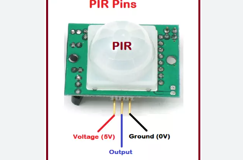
After learning about the pins, I connected it to the board (RED to 5V, BLACK to GND and BLUE to Output-MCU pin) that I had for testing. Then I programmed the board with connections from Arduino IDE. For programming the code was extracted from Google and edited as per my requirement. After successfully compiling and uploading the program, I tested and recorded video as shown below.
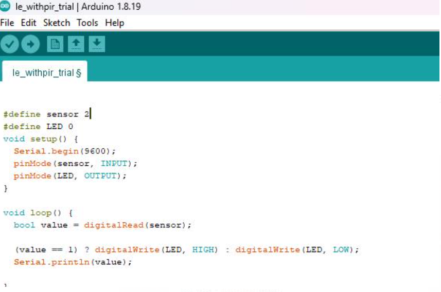
Codes
             # Define sensors 2
              # Define LED 0
              void setup() {
                Serial.begin(9600);
                 pinMode(sensor, INPUT);
                 pinMode(LED, OUTPUT);
               }
               void loop() {
                 bool value= digitalRead(sensor);
                 (value==1) ? digitalWrite(LED, HIGH): digitalWrite(LED,LOW);
                 Serial printIn(Value);
                }
Recording of Input Device Test
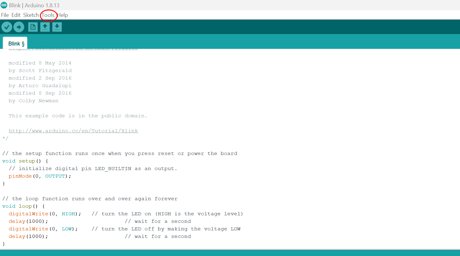
Before directly going into programming for the input test, you need to check if your board is working. To do that, open Arduino, go to examples and test blink test. Then go to tools as shown below.
Then have to select the type of board you are using. I have selected ATtiny 1614 from board manage as shown by image below.
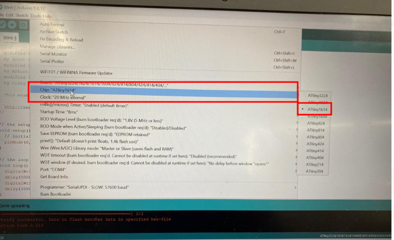
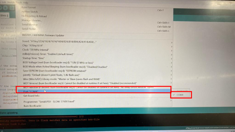
After board selection, choose the Port COM, a port where you have connected your board with computer. I have chosen port COM4 as shown below.
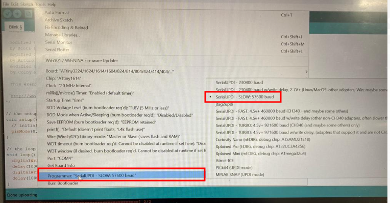
Then select the programmer. I used the serial UPDI -slow- 57600 baud as indicated by image below.
After all the selection, go to files>>examples >>Basics >> Blink test as done in embedded programming week.
Edit the code of examples as shown below, as per your pin and then verify, and upload.
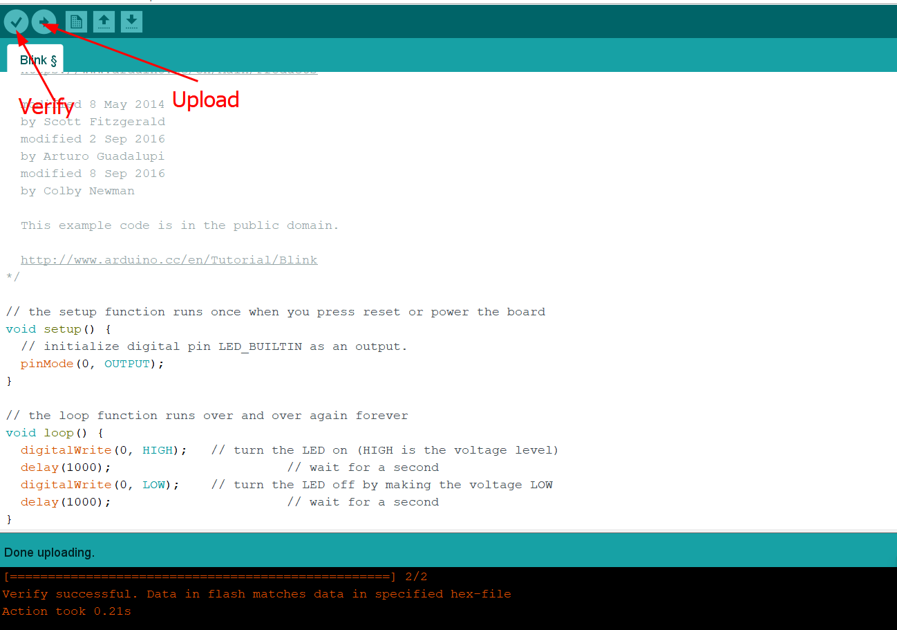
The code I used for example and test is embedded below for reference
// the setup function runs once when you press reset or power the board
                void setup() {
                  // initialize digital pin LED_BUILTIN as an output.
                  pinMode(0, OUTPUT);
                }

                // the loop function runs over and over again forever
                void loop() {
                  digitalWrite(0, HIGH);   // turn the LED on (HIGH is the voltage level)
                  delay(1000);                       // wait for a second
                  digitalWrite(0, LOW);    // turn the LED off by making the voltage LOW
                  delay(1000);                       // wait for a second
                }
After successful blinking test then I used input as PIR sensor and output as LED for confirming if my board works and turned out to be working successfully. Whenever I tried to pass around the sensor it detected my motion and then converted into LED blinking.
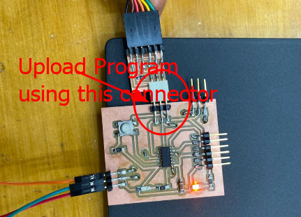
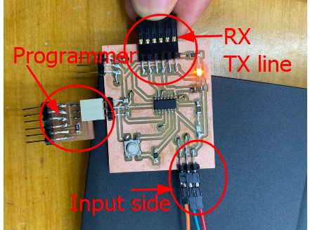
Uploaded the program using three pin connector which consisted VCC, GND and Pin connected to MCU.
And the hero shot of the input week is as described by the video given below.
I also tried to run a conformity test by disconnecting PIR sensor and connect to the power source and blue LED kept lighting and not blinking which meant my input device perfectly worked on my board.
Code
const int PIR_PIN = 8; // PIR sensor output pin
                const int LED_PIN = 0; // LED output pin

                void setup() {
                  pinMode(8, INPUT);
                  pinMode(0, OUTPUT);
                  Serial.begin(9600);
                }

                void loop() {
                  int pirValue = digitalRead(8); // read the PIR sensor value
                  Serial.println(pirValue); // print the value to the serial monitor
                  if (pirValue == HIGH) { // if motion is detected
                    digitalWrite(0, HIGH); // turn on the LED
                  } else { // if no motion is detected
                    digitalWrite(0, LOW); // turn off the LED
                  }
                  delay(500); // wait for 500 milliseconds
                }
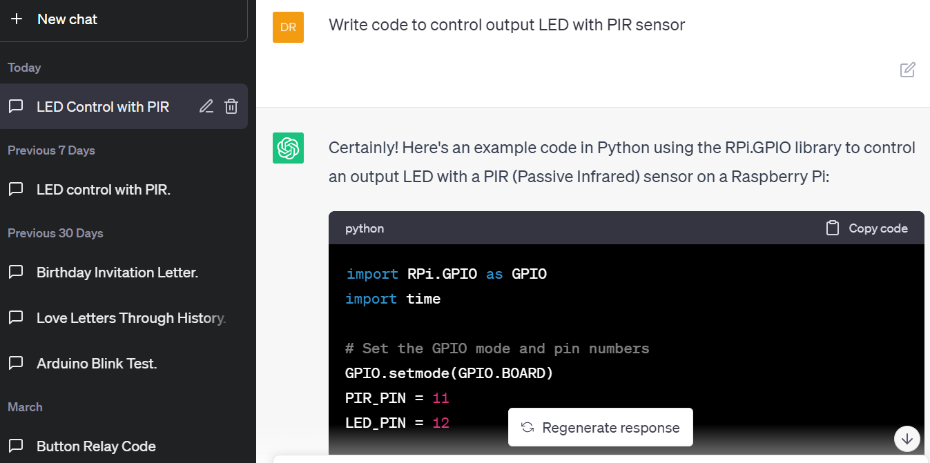
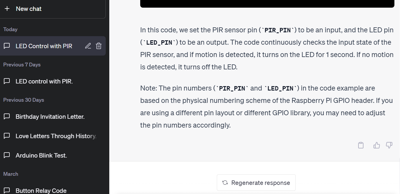
I got the code from Chat GPT to control OUTput LED with PIR sensor (I asked chatGPT to write a code to control output LED with PIR sensor and the following images show how I can edit and use it for my own board). And my PIR pin was connected to 11th pin of MCU which is 8 for programming and LED is connected to 2nd pin of MCU which is 0 for programming. In the code from ChatGPT I only had to change the pin numbers.
Issues and Challenges
Initially, I planned to use the input device which aligned with my final project but could not get and had to go for an alternative. I tried getting my input device i.e voice recognition module from online sites and it was out of stock. However, I have checked recently and it was available in the amazon.in and hopefully I can get for my final project. Meanwhile, I am looking forward to exploring other alternatives which can be simple but efficient in building my final project.
For the input week, I have used the same board as from the Output week and the design files are as below:
Design File
Schematic and PCB Editor