Mechanical Design, Machine Design
For the 10th Week, we were supposed to build any machine qualifying certain characteristics as described.Therefore, we were told to mainly focus on group work than individual assignment and we were divided into group of boys and girls by our instructors. We boys planned to make a machine that could fold T-shirt with detection sensor and motors.
Group Assignment
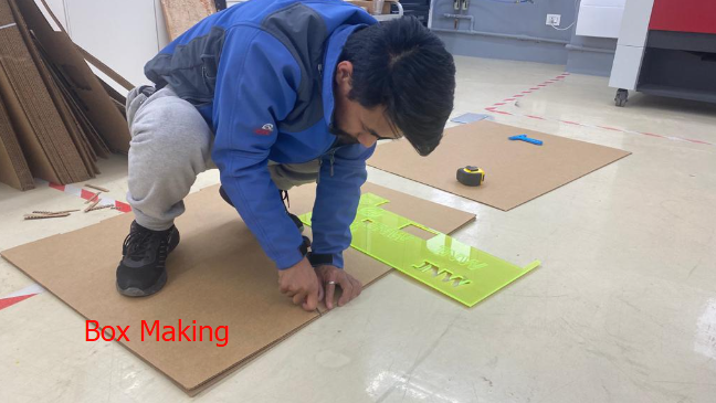
An idea for machine making was put on the table by Mr.Thinley and all three of us agreed up on their idea to start executing the plan which is to make T-shirt folding machine using motors and detection sensors. Holistically, we made the body of machine with card-board considering its weight which could be easier for motor as driver to move the leaves. We used 4 motors as driver, one card-board box as body as support to main moving parts, card-board with hinges as main shirt folder, motor anchors and larger wooden plank as grounding to fix motors at particular position. We are delightful of successfully making the machine that works and we used all the raw materials that are available in the lab.
Link to the Group Work Bhutan FAB23 Machine Building Group
Individual Assignment
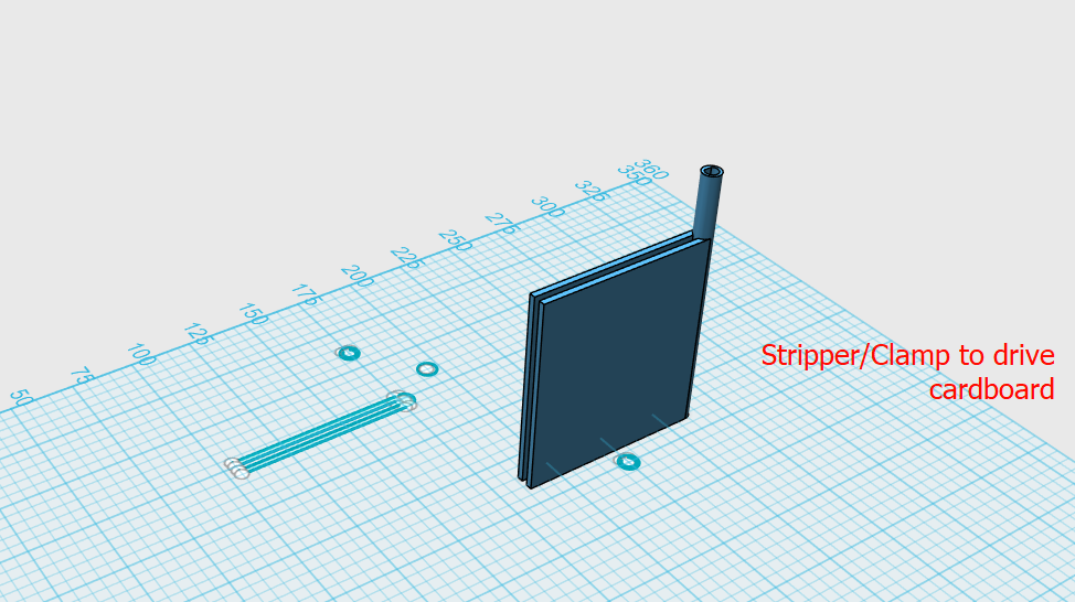
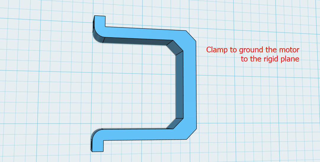
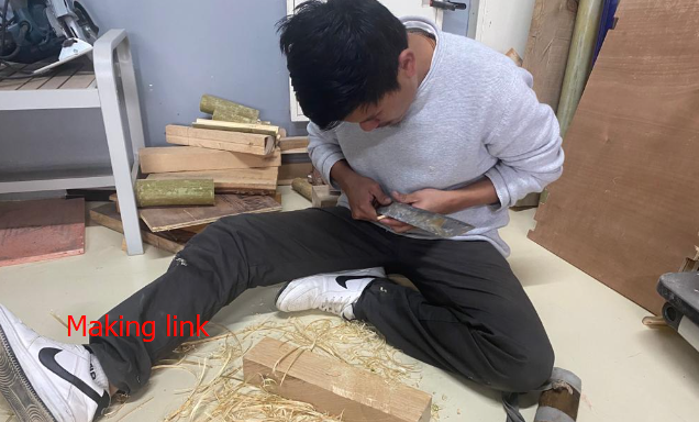
For making the group work successful and speed up, we thought to assign work individually and therefore, I and Tempa started with designing and making couplings for motor and clamps, making the links for clamps and motors, body to support, and cutting the grounding plank. where Mr. Thinley was heavily involved in programming and making the shirt folder with card-board in zund.
Clamps are 3D printed and it took lot of hours and many of the machines in the lab were always occupied with other projects and we really had to manage to get our things printed. Most often, when we tried to fix/join the components, clamp's couple part broke down and we had to re-print for several times.
Other components and manufacturing process
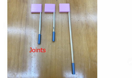
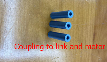
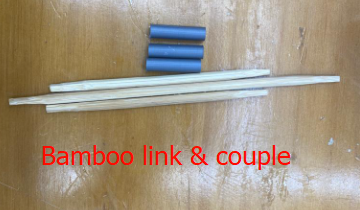
We made the joints/links with bamboo, body box with card-board, clamps and couplings are 3D printed. Coupling had to be very small as the shaft from stepper motor was small and that made us difficult from strength point of view.
Issues and Challenges
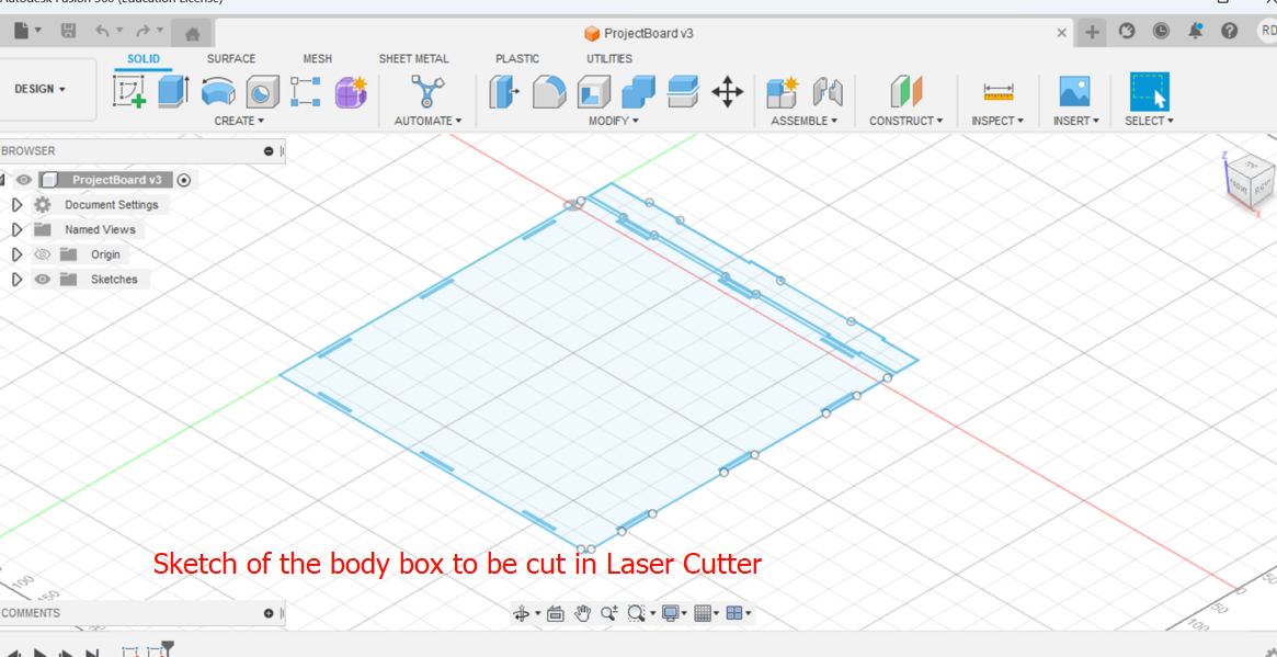
To make this machine work, it took lot of hard work and sacrifices. ALthough the end result looks quite fine, we had to invest tremendous amount of time and expertise. Moreover, it involved many processes like designing for 3D printing and cardboard base, and also all the system as whole. The following are some of our work flows:
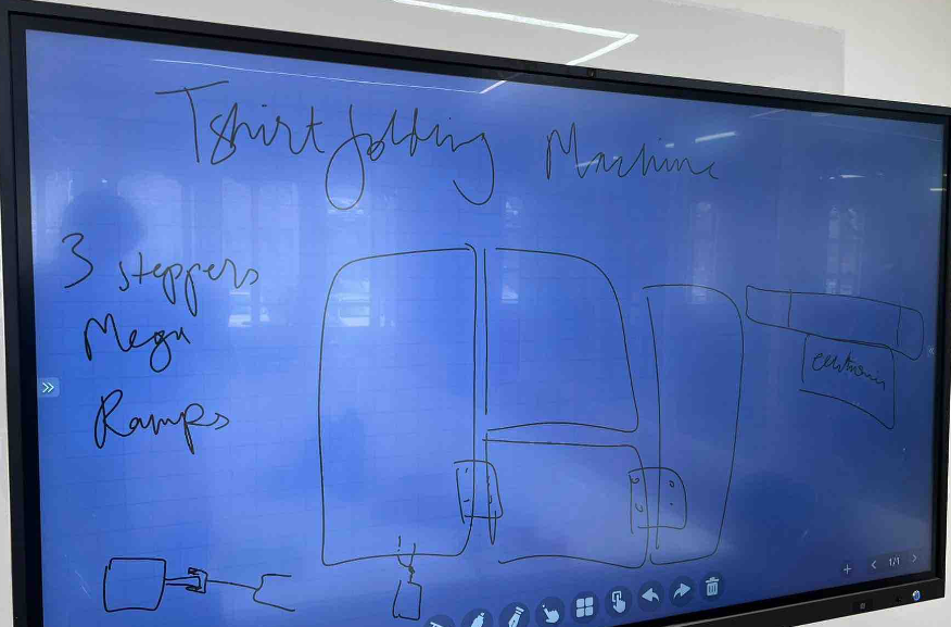
The first step was to generate an idea that qualifies as the assignment of the week. Mr. Thinley from the group came up with an idea and we all agreed to make machine that can fold T-shirts. Then drew a hand sketch and presented to Mr.Rico and Ms.Zina which they approved. The rough sketch as shown below:
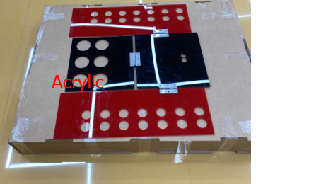
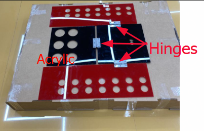
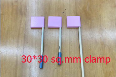
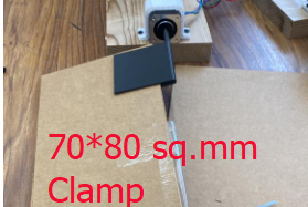
After the sketch, we agreed to make the components to fold the shirt with an Acrylic that was available in the lab and tried to make it rotate with the motor but motor did not have capacity to rotate the acrylic. We also increased the dimensions of the clamp from (30*30 sq.mm) to (50*50 sq.mm) and again to (70*80 sq.mm) thinking if it is the clamp that is not transferring enough power to acrylic and still it didn't work. Acrylics were joined using the door hinges as shown below:
Next we shifted our idea from using acrylic to using cardboard considering its lighter weight. Then tried to rotate it with motor(but the card-boards were not joined and we tried with individual components)along with bigger clamp (70*80 sq.mm) and motor could rotate them. But there was problem with our hinges and therefore modified the hinge design: Because we test run with the cardboard without hinges and it deviated when motor was activated. No hinges used.
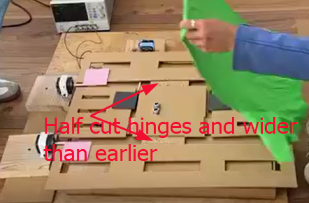
Then we thought og integrated hinge and we agreed to make from cardboard without having to incorporate external hinge unlike in the acrylic board idea. We tried with same idea ( that is to cut the cardboard to half of its thickness by not cutting all the way through vertically) and it worked but got problem with smaller width of the hinges and we increased the hinge width just enough to fit in the coupler so that coupler can rotate 180 degrees freely. And image shown below for the comparison:
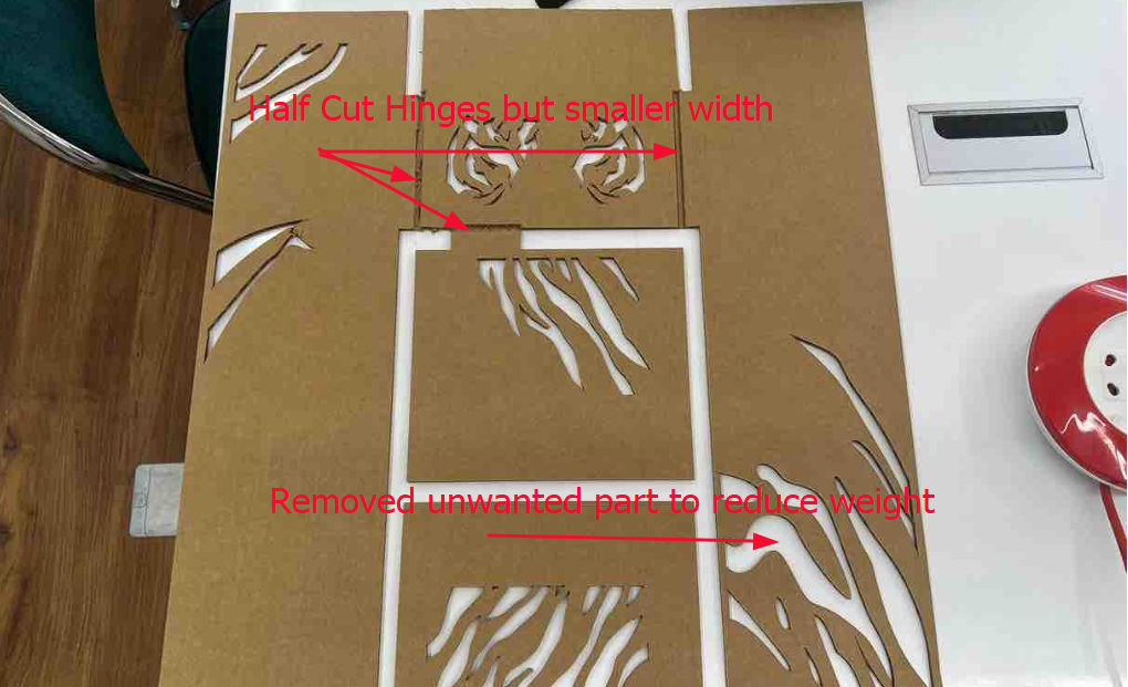
In these two images, you can notice the differences in design of the cardboard focussed to reduced the weight. For the first one, design was complicated it made harder for zund cutter to cut and for once the tip got broken. Therefore, we changed the idea to make the simple design into second image for the safety of machine.
Again after this, our motor could rotate the cardboard unfortunately, it didn't work synchronously. We could not rectify the problem and approached Mr. Thinley Jamtsho of DHI/JNWSFL who was at his best in IoT. Then he told us to add delay in the coding and we did, then it helped us sort the things out. Prior to this we only coded for rotating the motor but not on how smoothly the motor should rotate and it made the motor rotate in sudden can it gave jerk to all the components. Regretfully, we have not recorded all the videos.
After all of these modifications and redoing, we could make our machine making week a wonderful experience. At first glance we though like we could do machine making in the very first week, but ultimately it took us to te final day of the second week itself.
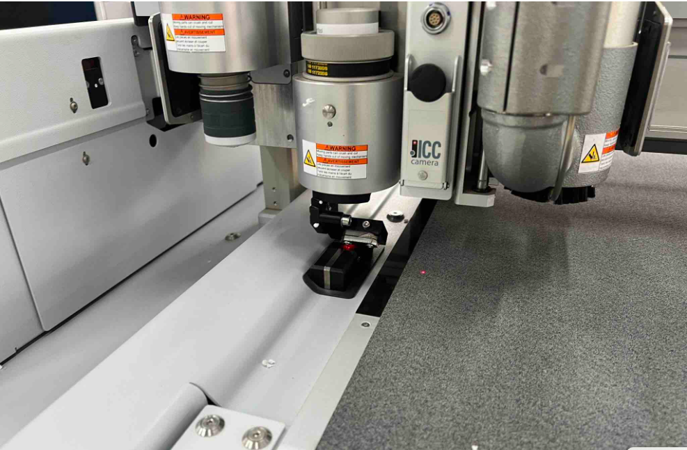
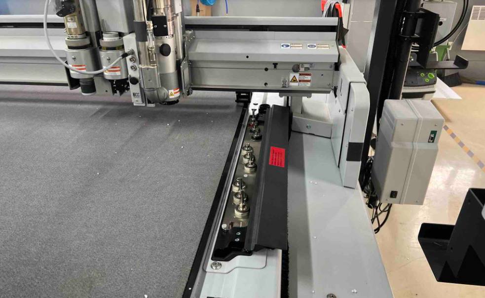
About Zund (Mega Machine)
I was also new to the Zund cutter however, Mr. Thinley was in-charge of that machine and he could holistically demonstrate the usage and capabilities of the machine which enhanced our group's comprehension on basics of machine. I got curious and for more comprehensive usage I skimmed through operating manual online PDF. From there I learned that the Zünd is a modular cutting and marking system capable of working with a wide range of materials, including paper products, leather, fabric, felt, flexible and rigid foam, plastics, composite boards, wax, non-ferrous metals, and more. Vector-based 2D drawings are used to define where the machine will cut, layers can be used to specify cut order and to assign cut depth and operation type to vectors within a single file. A camera mounted to the tool carriage can detect edges and other registration features, aligning operations with edges of the media or printed graphics.
Work Flows of the The Zund G3-L2500
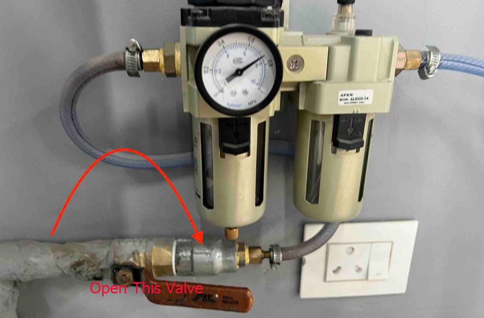
1. Powering Machine: Need to turn on the compressor of the machine as shown:
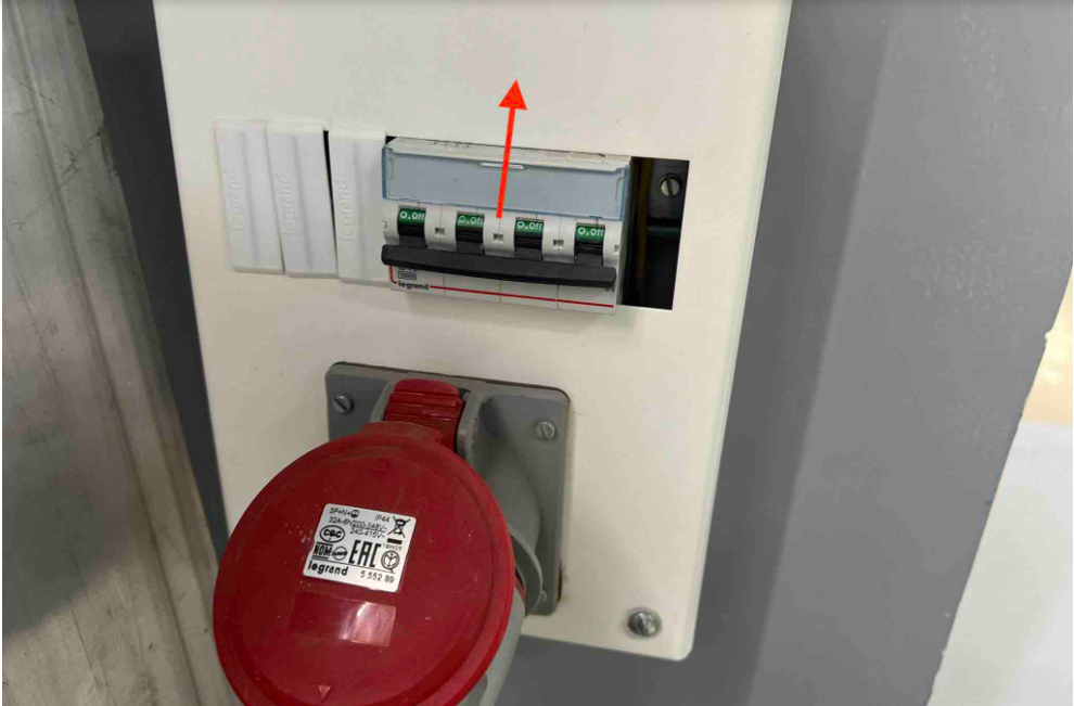
2. Turn on the main power supply of the Zund from the MCB. The Zund’s operating screen will power up:
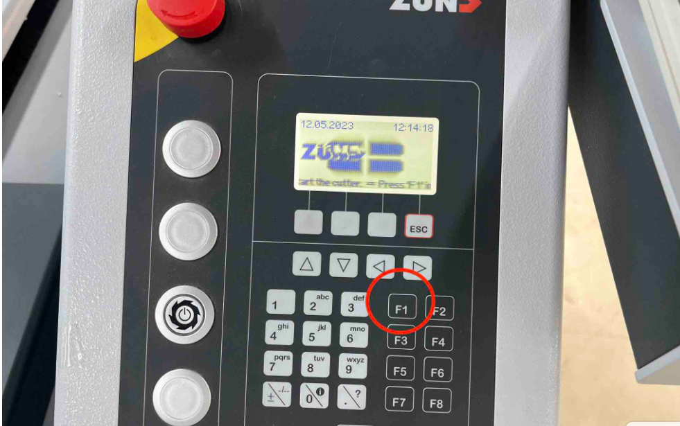
3. Hit F1 to begin initializing the machine. (the operating screen will tell you that you can start with F1):
4. After hitting F1 DO NOT touch anything while the machine initializes itself. The modules will come towards the PC and operating screen once initialization is done.
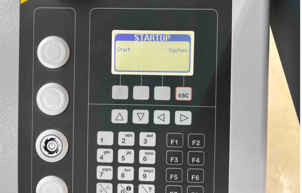
5. In the meantime turn on the PC
Initializing the tools
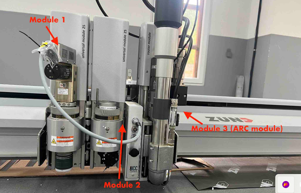
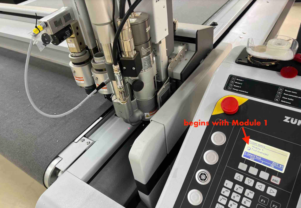
Zund has three module slots. The operating screen will begin with module 1. Check that the tool displayed on the screen is the same as the the tool thats currently in the module 1 slot.
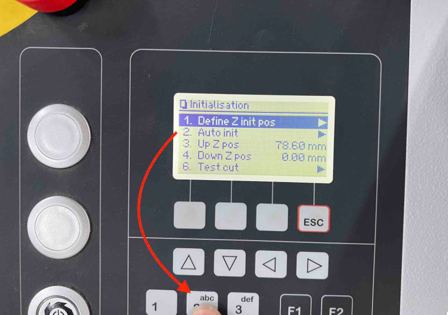
After confirming, hit init. This will take you to the initialization screen.
In the Initialization screen, hit 2 on the keypad to Auto init. Hit okay to start.
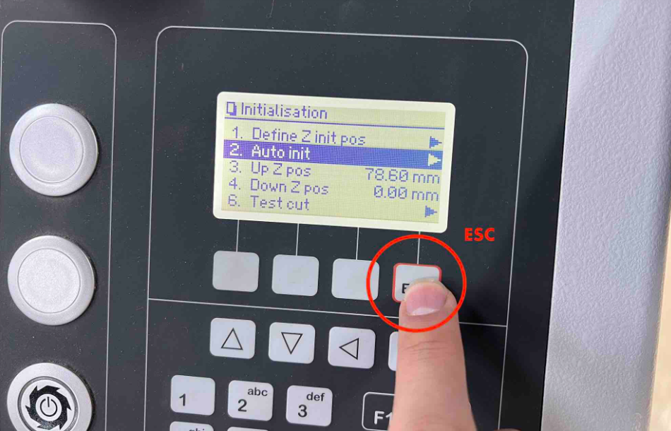
Once the Auto initialization is done hit ESC on the keypad to save that.
Then the machine will move on to module 2. Ensure the tool displayed on the operating screen is the same as the tool in module 2 and conduct the same initialization process as above.
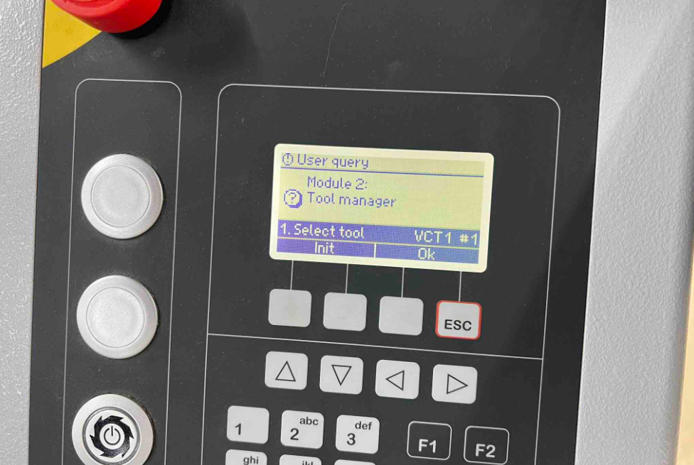
Module 2 Auto-Initializing
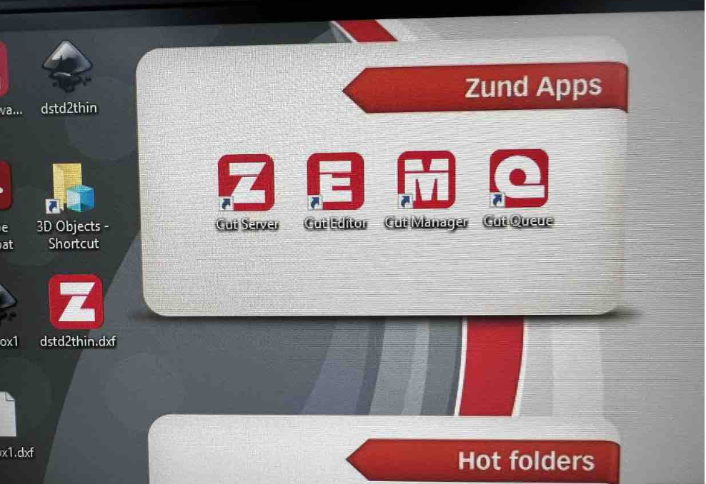
Design Software
After completing the initialization of the machine and its tools, we will move on to the Zunds PC.It has four main applications or apps. Namely:a. Cut Server this just connects the pc and machine to the same server so no need to touch this. b. Cut Editor This is where all the design editing, material selection and processes are assigned. c. Cut Manager This is where all the hardware, tools and material settings are stored. No need to touch this unless you want to add a new material that isn’t there already. d. Cut Queue This is where all your new and old jobs will be queued after finishing the settings in Cut Editor. e. not shown Cut Center the final app where you assign the tool and bit you want to use to each process along with the tool’s functioning settings.
After all these, you can go to cut editor of the machine PC and start designing your drawing or else you can have your drawing in .DXF format which is readable in the cut editor.