Out Put Devices
An output devices are pieces or equipment/hardware that gives out the result of the entered input, once it is processed/Output devices are components that send data from a computer to a user or to another device.. Examples like printer, monitor, LED, bulb etc.
Group Assignment
This week, we were tasked to measure the power consumption of an output devices. To do this, we used the formula:
We checked the power consumption of an LED first and compared this at different voltage supplies. In order to carry out this task we created a simple circuit on a breadboard which consisted of this LED and was connected to a gwinstek power supply.
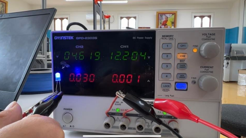
We supplied 4.6V to an LED and found that current is 0.030A (current denoted by red digits at CH2 side on the machine) and applying P=VI we get,
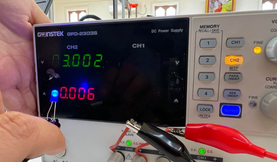
At 3V supply, current is 0.006A. Therefore using the general formula P=VI
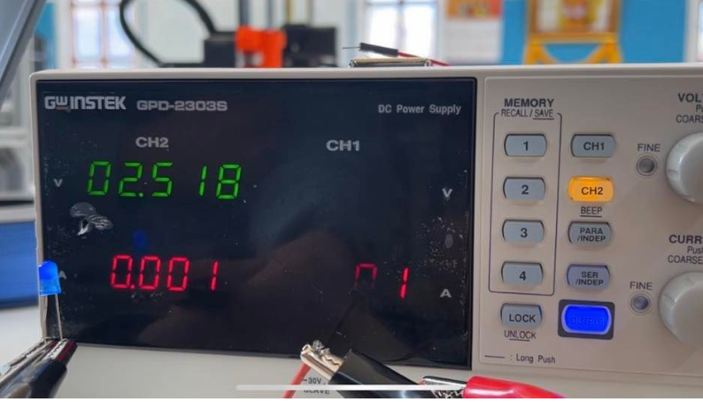
At 2.5V supply, the current is 0.001A. Therefore Power = VI
General observation is that as we decrease the supply voltage, the current decreases and consequently the power consumed by LED also decreases resulting into less brightness of LED.
Checking Power Consumption of Servo Motor
Next we wanted to check the power consumption of a servo motor. We created a simple circuit using a servo motor, breadboard and Arduino Uno. We used the following code (from Zina) to ensure that the servo would continuously turn and stop after a delay so we could study the power consumption during functioning as well as at idle state.
            void setup()

{

    pinMode(0, OUTPUT);

}

void loop()

{

for (int i = 0; i < 90; ++i) {

  digitalWrite(0, HIGH);
  delayMicroseconds(2000);

  digitalWrite(0, LOW);
  delayMicroseconds(18000);

}

for (int i = 0; i < 90; ++i)

{

  digitalWrite(0, HIGH);
  delayMicroseconds(1000);

  digitalWrite(0, LOW);
  delayMicroseconds(19000);

    }

}
From this experiment, when you supply the uno with 4.9V, you could see the current fluctuating from about 0.3 A to 0.1 A during functioning and during its idle state. When calculating the power, it comes between 1.47w to 0.49w which indicates that the power consumed in running state is highest and lowest in idle.
Link to the group assignment: Bhutan FAB23 group
Individual Assignment
Individually, we were required to design a board that can be used to integrate with output devices for which I designed for servo motor and relay. I chose output as relay because my final project in on light control by voice command so relay is required to power up from PCB to the bulb./p>
Designing Board for two output
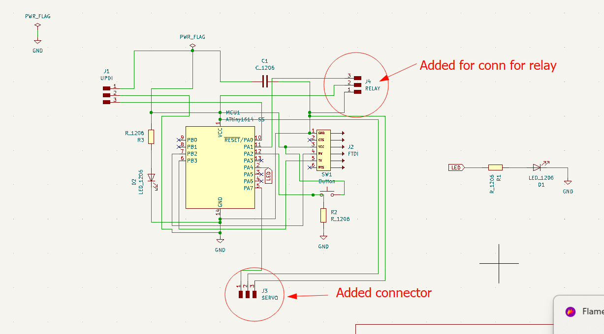
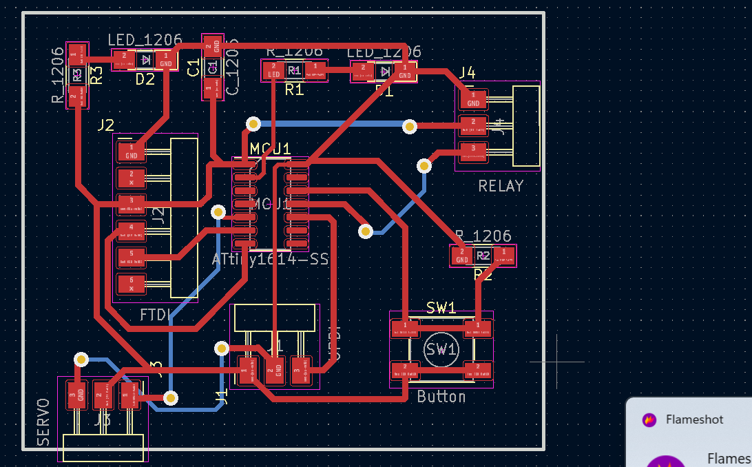
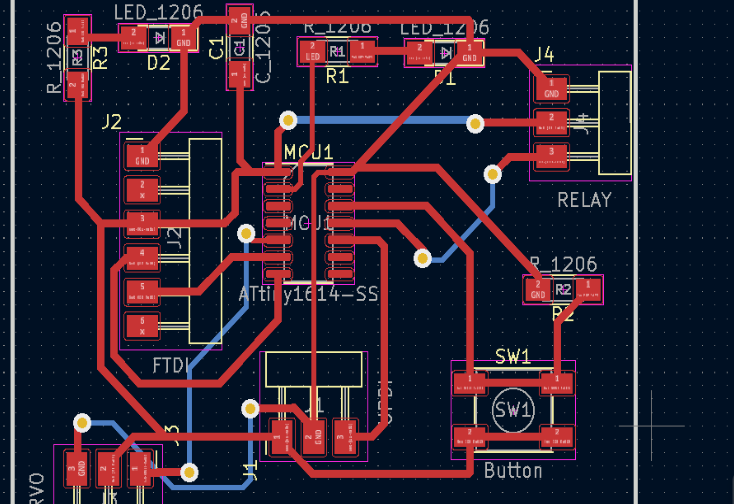
As always started designing board from schematic, however, since I have designed already for LED blink test it was easy for me to design for two outputs. Which means I could just add connectors to the schematic that I designed for LED test. The design is as shown by schematic diagram below and PCB editor respectively.And design files are at bottom of page.
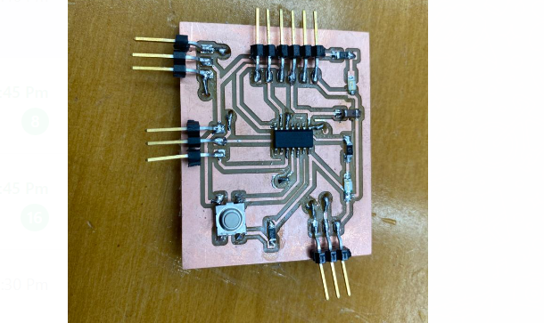
After designing and troubleshooting, I milled the board and then soldered. This time I was much better and took lesser time to solder as well as milling the board.
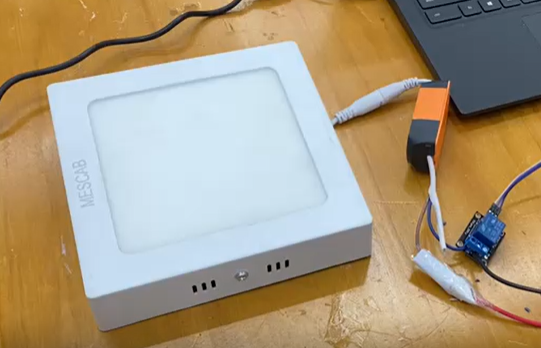
Testing output 1 (Relay)
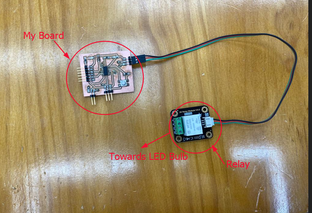
I tested my board to control relay as output device 1 which means testing my board if it can control the relay to power up the LED bulb of 230V. And for that I tried with push button as well as serial monitor which it went successfully. However, I'm grateful to Mr.Cheche for the assistance provided with debugging and coding. Green wire connected to Data line on Relay and Pin number 11 on MCU, red wire to to VCC on board and to VCC of relay, then black to GND on board and to relay respectively as shown below:
Specifications of the Components that used for Output Device
I have used extension cord to connect the terminals from LED bulb to relay(Positive terminal to extension cord and Negative to the relay) which is 230V normally and for programming the board, the programmer connector is is connected to UPDI and to the computer.
Debugging
I used the same board that I had milled for LED blink test for out put device. Therefore, on that board I had to connect two more connectors of three pins. I added the connectors in schematic diagram but on PCB editor routing the paths got intersected which violated the design rule. Then I had to drill the hole on my board to connect that pins to avoid intersections as shown below: The blue lines of the PCB indicates requirement of drilling hole to make it through hole design.
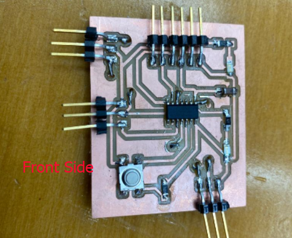
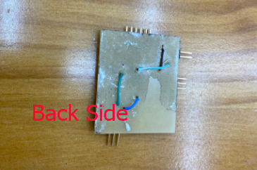
The following images show how my board looked after soldering and making through hole. It took time to edit the routing and best solution was to make through hole to make the work faster and easier.
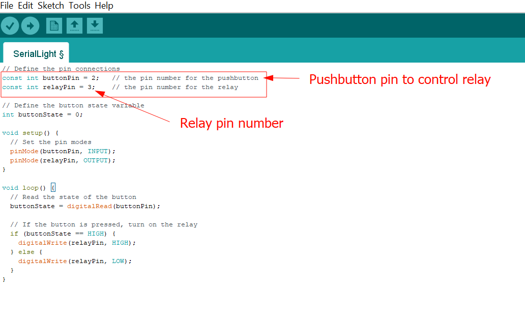
Push Button (Relay)
Code for pushbutton Relay
        // Define the pin connections
const int buttonPin = 2;   // the pin number for the pushbutton
const int relayPin = 3;    // the pin number for the relay

// Define the button state variable
int buttonState = 0;

void setup() {
  // Set the pin modes
  pinMode(buttonPin, INPUT);
  pinMode(relayPin, OUTPUT);
}

void loop() {
  // Read the state of the button
  buttonState = digitalRead(buttonPin);

  // If the button is pressed, turn on the relay
  if (buttonState == HIGH) {
    digitalWrite(relayPin, HIGH);
  } else {
    digitalWrite(relayPin, LOW);
  }
}
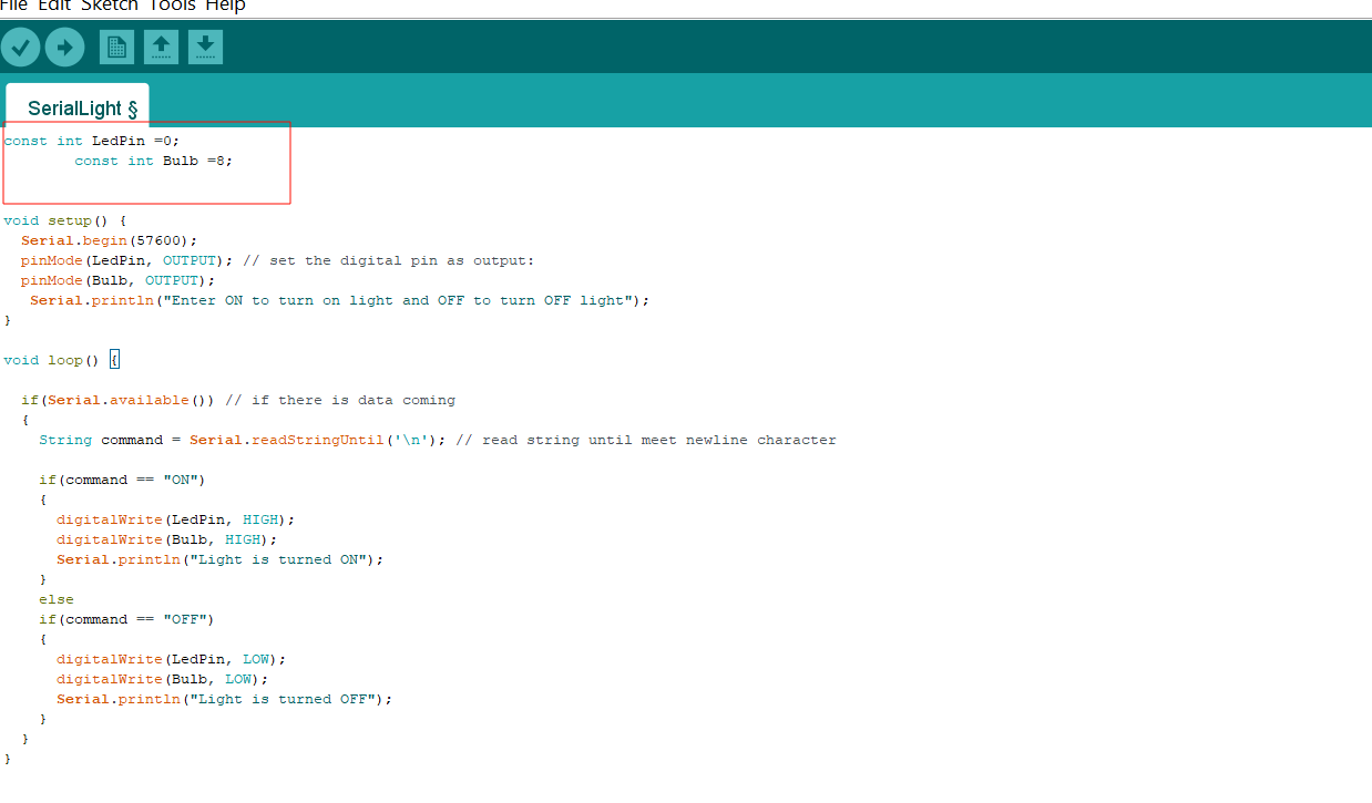
Serial Monitor Relay
Code for Serial monitor control
        const int LedPin =0;
        const int Bulb =8;


void setup() {
  Serial.begin(57600);
  pinMode(LedPin, OUTPUT); // set the digital pin as output:
  pinMode(Bulb, OUTPUT);
   Serial.println("Enter ON to turn on light and OFF to turn OFF light");
}

void loop() {

  if(Serial.available()) // if there is data coming
  {
    String command = Serial.readStringUntil('\n'); // read string until meet newline character

    if(command == "ON")
    {
      digitalWrite(LedPin, HIGH);
      digitalWrite(Bulb, HIGH);
      Serial.println("Light is turned ON");
    }
    else
    if(command == "OFF")
    {
      digitalWrite(LedPin, LOW);
      digitalWrite(Bulb, LOW);
      Serial.println("Light is turned OFF");
    }
  }
}
Programming the Board (Arduino IDE workflow)
For programming my board for controlling relay using push button I used Arduino IDE 1.8 and extracted code from google Codes. From this code I just had to change the pin numbers and it is as shown below by image.
Likewise for serial monitor relay control, I used from same link and changed into "ON" for turning on and "OFF" for switching off.
Design File
Schematic and PCB Editor