Computer-Controlled Machining


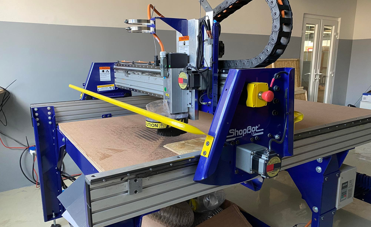
Week seven was about Computer Controlled Machining, making or operating machine called ShopBot which is controlled through computer numerical. Fundamentally, designs were made in the software Fusion360 and tool path is generated based on designs so that the machine can cut following this path ultimately producing the product.


                                                ShopBot in JNWSFL


Group Assignment


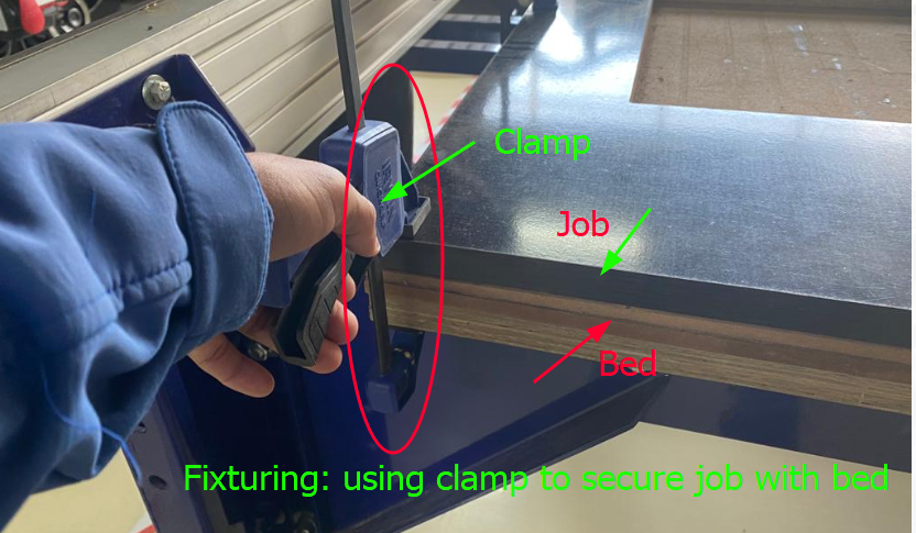
For the group assignment, we were required to attend safety training, test the runout, fixturing, alignment, speeds, feeds of the machine. The link to group assignment is Bhutan FAB23 group.
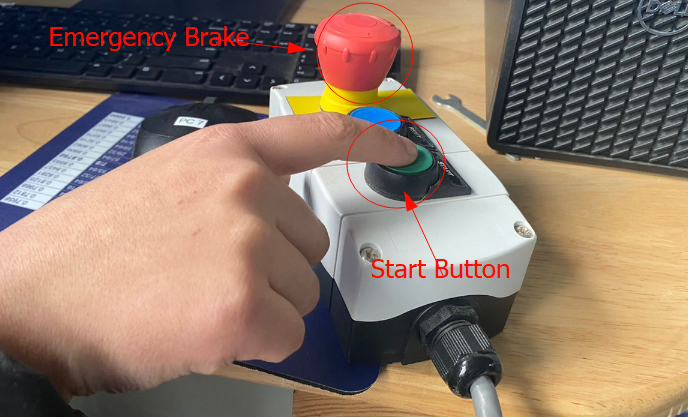
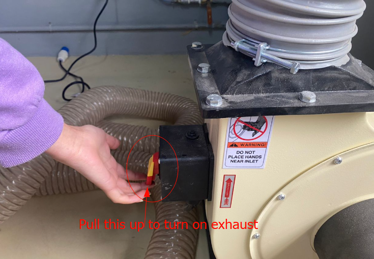


Safety Protocols


Under safety protocols there are two aspects to be taken care of which are Safety of Machine and Operator(User). For user/operator safety, it mainly deals with Personal Protective Equipment (PPE) and they are mandatory to put on when operating ShopBot for it being heavy duty and accident prone machining if not taken care as listed below :

  • 1: Goggle for eye protection from flying debris/chips
  • 2: Ear muff/bud for ear protection as the operation of this machine is noisy
  • 3: Safety boot for preventing your feet from accidental falling of heavy job pieces or other sharp tools
  • 4: Gloves for hand when handling rough/sharp job pieces and heavy products Note: Not to use gloves when dealing with end mills in operation as gloves can get stuck and cause accidents.
  • 5: Mask, use face mask to prevent dust.
  • 6: Safety helmet for head protection
  • 
            
    Safety Gears Clamping job to bed
    
            
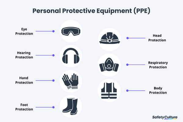
    An Image from Google


    Run-Out


    To check the run out of machine in JNWSFL, we tried cutting 3 square boxes with parameter setting, (1) outside cut (2) On the line cut (3) Inside cut. Theoretically, the box of outside cut has to fit in the slot of inside cut, but in reality our outside cut box did not exactly fit. Therefore, we found out that there is run out of approximately 1mm. We also tried using dog bone, which made it easier to fit journal in the slot.


    Optimizing Speed and Feed Rate


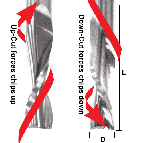
    We followed the manual for characterizing this or you can get information from SHopBot Manual. Started off using an RPM derived for the chip load for the material being cut (Material was MDF-Medium Density FiberBoard). Increase the cutting speed (feed rate) until the quality of the part finish starts to decrease or the part is starting to move from hold downs. Then decreasing speed by 10% and decrease RPM until finish deteriorates, then bring RPM back up until finish is acceptable. We tried for 1/4" end mill for up cut (Up cut bit is designed to quickly move chips up and away from the surface being cut. The grooves in the bit will pull the debris up so that it will not stay in the area being cut. The design of this tool means that it is able to be used at a higher speed than some other tools) and down cut (its method of chip removal is to push the chips down into the surface, which can make it less effective and you will need to consider some form of vacuum to clear them away. Down cut bits require lower speeds to produce quality goods and will produce a fantastic finish on the top of the piece).


    Chart of feed rate for MDF End Mill difference


    Individual Assignment


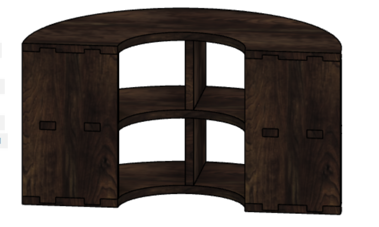
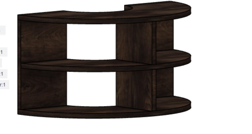
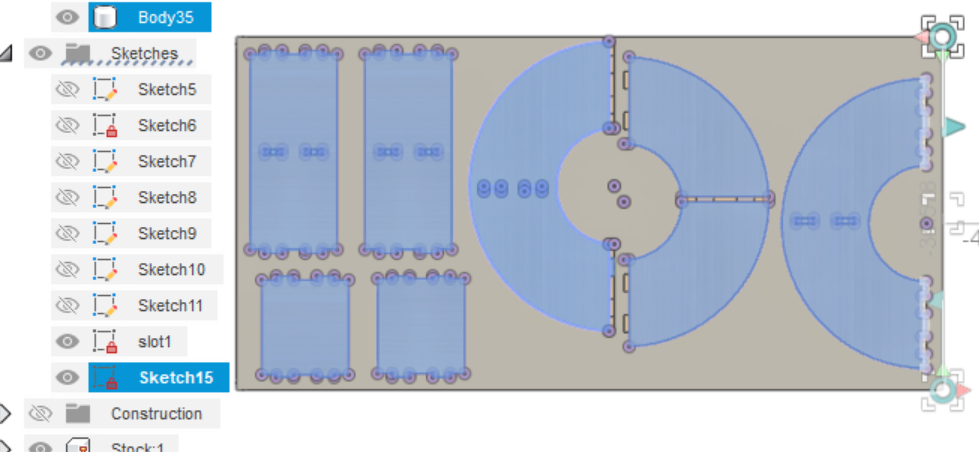
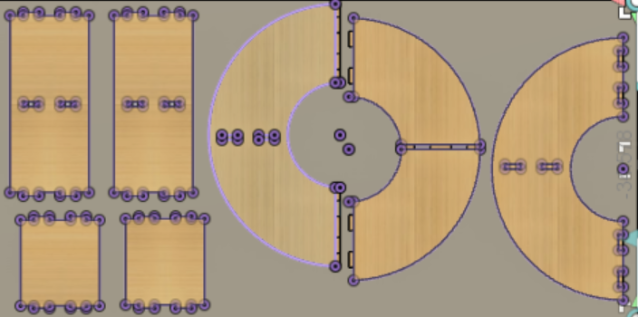
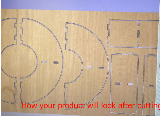
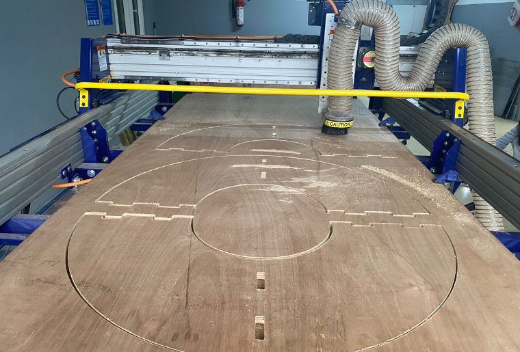
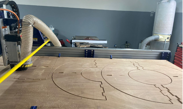
    We were required to make (Design+Mill and Assemble) the product of minimum one meter using ShopBot. Therefore, I designed a half-radial shoe rack with exterior diameter of 1000mm with three layers in Fusion360. We were given a job of 8*4 sq.ft from which we can make our product.


    Look of my product Look of my product
    
            
  • The components of this design should fit in the job size provided for which I had to lay and check.
  • 
          
    Laying my components Laying my components
    
          
  • After laying all the components and check if all of these fits in the given job size, if it does, then project to get the 2D sketch from your 3D components. Only 2D sketch could be read in the VCarve (Software to run the ShopBot). After your projection, you get the purple line connected with dots as shown below which means your 2D Sketch is ready.Then right click on the sketch and Save as DXF file.
  • 
          
                                                    Preview of 2D Sketch


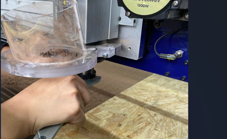
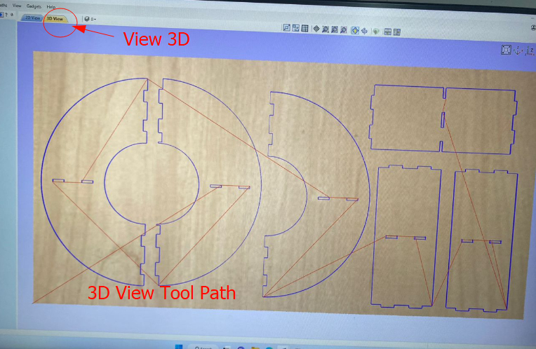
    WorkFlows of operating ShopBot


    After your design is ready, it is time to operate ShopBot to machine your product. Before directly operating, there are certain settings which should be set.

  • 1: Tool Setting-fix the collet into its holder>>insert tool/end mill in collet>>Hand tighten>>Then tighten with spanner and collet spanner>>Fix collet in the spindle head and tighten with spanner.
  • 
            
    Collet Tighten Tool Fixed
    
            
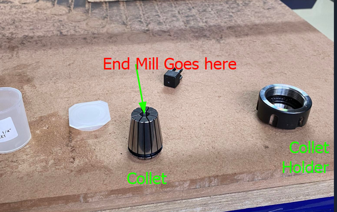
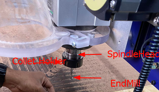
    Note: Its important to see that the collet and end mill sizes are same when fixing end mill to collet.
  • 2: Setting X-Y Coordinates- This is to ensure that the cutting starts from the area where your design is placed. Spindle attached to gantry moves in two directions which is longitudinal(X) and Horizontal (Y).
  • 3: Job Set Up(Zero Plane setting)- After placing/laying and fixturing the job on machine bed, set the zero plane. For that clip crocodile clip to spindle body from *top*>>Place plate on the job surface>>Then press Z-button *up or down signal from computer*. This is to ensure that that the point of end mill is exactly on the surface of the job.
  • 
            
    Tool Fixed Laying Plate Z set


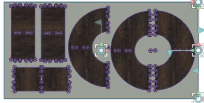
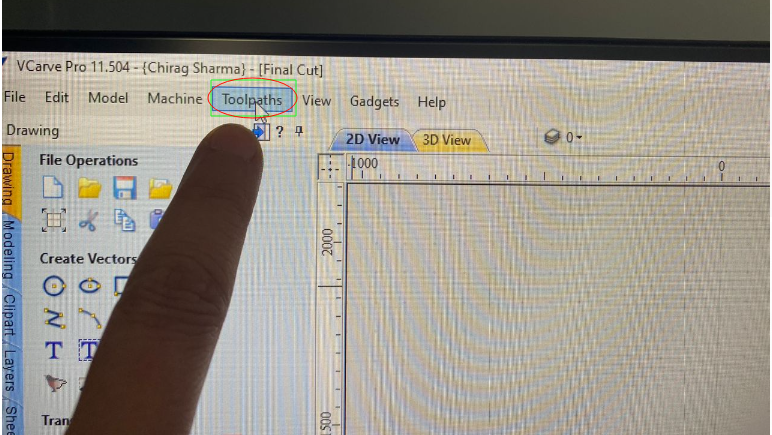
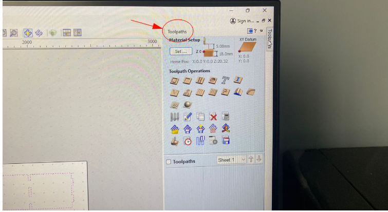
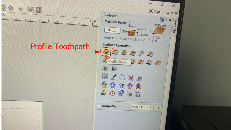
    Cutting/Machining Using VCarve


    Open the VCare software which is installed in the computer that is connected to the ShopBot


                                                  VCarve Opening
    
            
  • 1: Import the DXF file in above working window, and set parameters shown by image
  • 
            
    Importing DXF file Window description
    
            
  • 2: Go to Tool path from Left corner or right corner as shown below. This is to generate tool path and cut your design/ or engrave.
  • 
            
    Toolpath Toolpath
    
            
  • 3: Under tool path you see multiple options to choose from, but I chose profile tool path so tha it can cut slots>>Start Depth>>Cut Depth>>End mill size>>Machine Vector(Outside cut-cuts from outside line, Inside cut from inside of line, Online cut will cut exactly on the lines)>> And hit calculate.
  • 
            
    Showing profile tool path Calculating tool path
    
            
  • 4: Preview of tool path is shown depending on your design. You can also see it in 3D view.
  • 
            
    2D Toolpath 3D toolpath Product preview
    
            
  • 5: After calculating the tool path, press the green button (Start button) on the controller and you will hear the priming sound. Note:Before that start the exhaust system.
  • 
            
    Start button Exhaust system
    
            
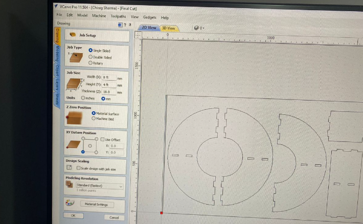
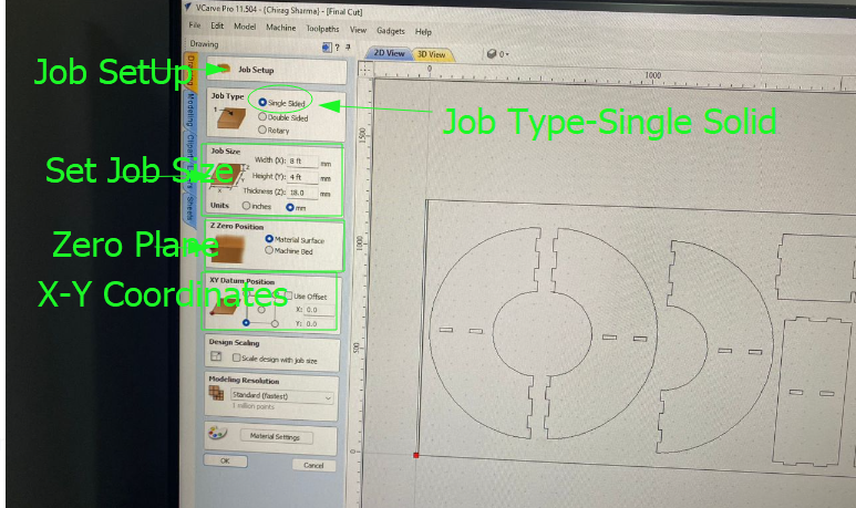
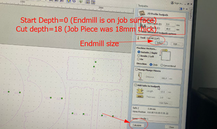
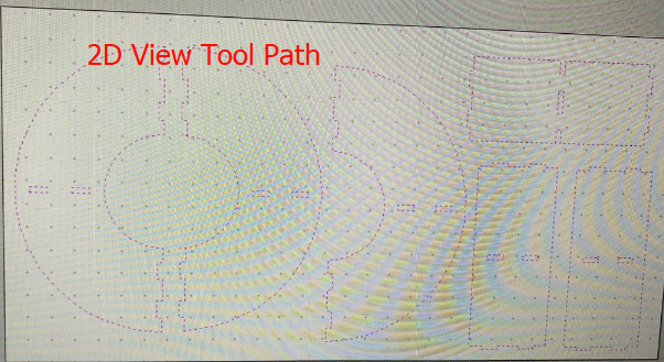
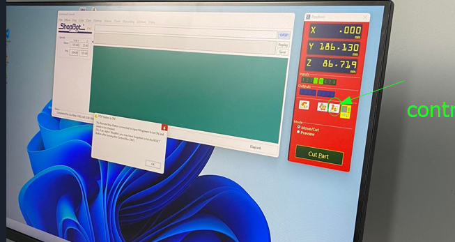
    Setting Machine Parameters


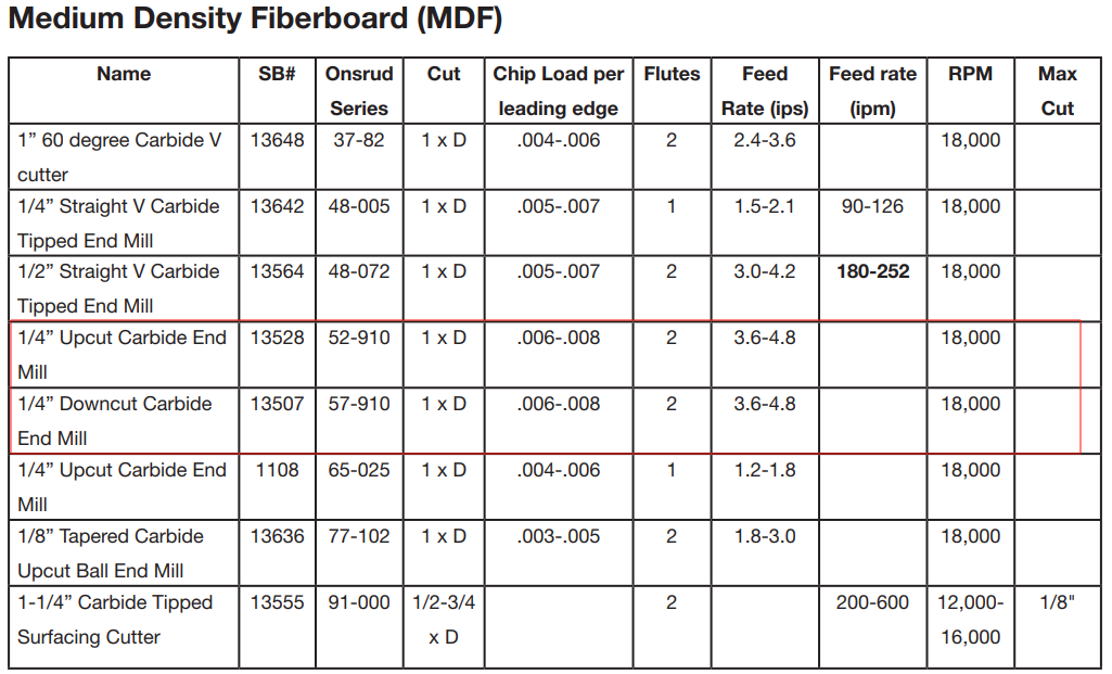
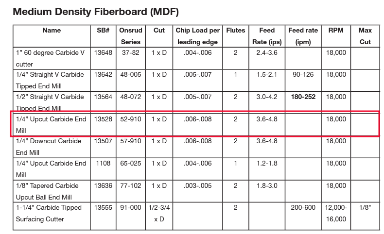
    Machine parameters like spindle speed and feed rate has to be set before really start machining. Therefore, to cut specific job material, there is certain speed and feed rate to be checked and I cross-checked with the manual of shop-bot and used the speed from MDF (Medium Density Fiberboard). That is using 1/4" up-cut carbide tool at RPM 18000 (Spindle speed) and 4 inches per second feed rate.The image below gives good idea of setting machine parameters relative to the type of job material.


                                                  Setting Speed
              
            
  • Now that machine will start cutting and the following are some pictures in process of cutting.
  • 
            
    After cut Process of cutting
    
            
  • 6: After the cutting is finished, we require to sand the cut parts to remove sharp edges/corners and rough surfaces. Then I assembled my product.
  • 
            
    Products Assembling Assembling


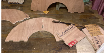
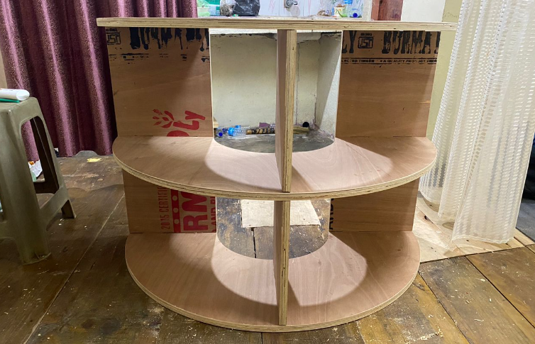
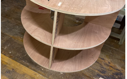
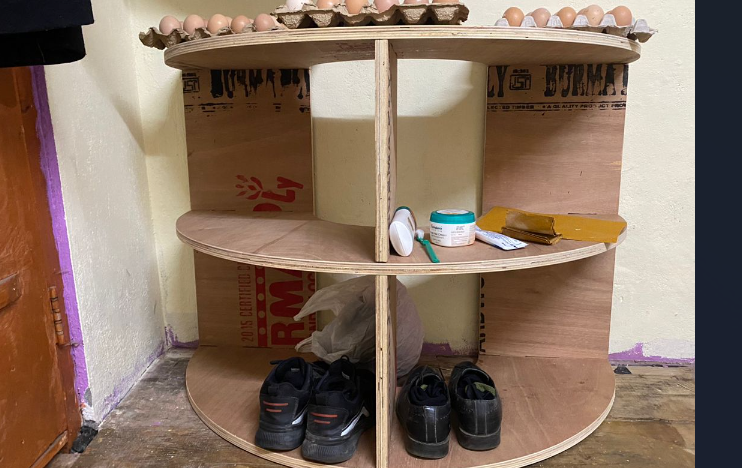
    The hero shot of the product that I made can be seen as shown below. Initially, I planned to use it as a shoe rack but turns out it can be used to store egg trays!


                                                  product made to use


    Experience


    I had the experience of using Shop-bot and and setting it up but it was my first time to use VCarve to edit my 2D sketch and control the cutting which further encouraged me to learning about the machine. I was bit afraid of using Shop-bot during FABZERO program but the experience changed marginally during FABACAD23 and I felt comfortable using the machine which indicated that I was much familiar with the safety procedures and use of the machine. Overall, I knew that this machine can build any product that best fits the requirement of every individual at home provided the safety of both man and machine is taken care of.


    Design File
    Sketch and 3D.