3D Scanning and Printing
Group Assignment
The group assignment was about testing design rules of the 3D printers at lab. Therefore, we downloaded the testing model from the link Design Rules Test Model to check on parameters like:
Link to Group Assignment work: Bhutan FAB2023
Observation/ Learning
Overhang test- From this test I came to know that support is required after an angle 60 degree. However, giving support from 45 degree can be better but it increases material cost and post-processing. Bending Test- From this, bridging was not that good after distance of 3cm. However, it can be good to avoid bridging failure by giving support.Micro-engraving- Minute letters weren't printed good, therefore, it is advisable to avoid using letter size below 5mm. Note: This experiment gave us a good point of reference as to what expectations that our printer in our lab will be working as per design rule.
Individual Assignment
The fifth week of Fab Academy 2023 was about 3D scanning and 3D Printing which I was quite familiar with. Therefore, it did not look intimidating unlike other weeks. However, 3D scanning machine at SFL was non-functional and we were asked to download & install Kiri Engine on phone and scan 3D objects. For 3D design & printing, we were asked to design and 3D print an object (small, few cm3, limited by printer time) that could not be easily made subtractively.
3D Design and Printing
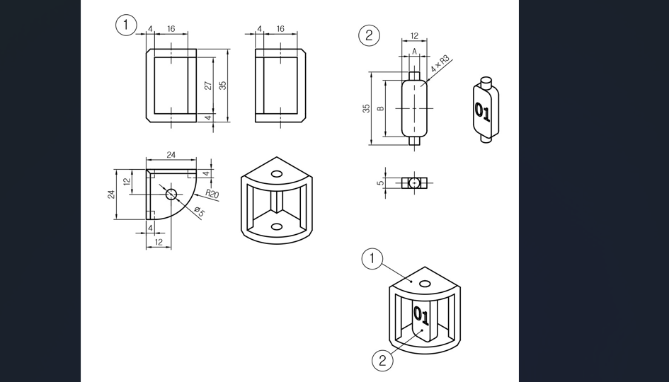
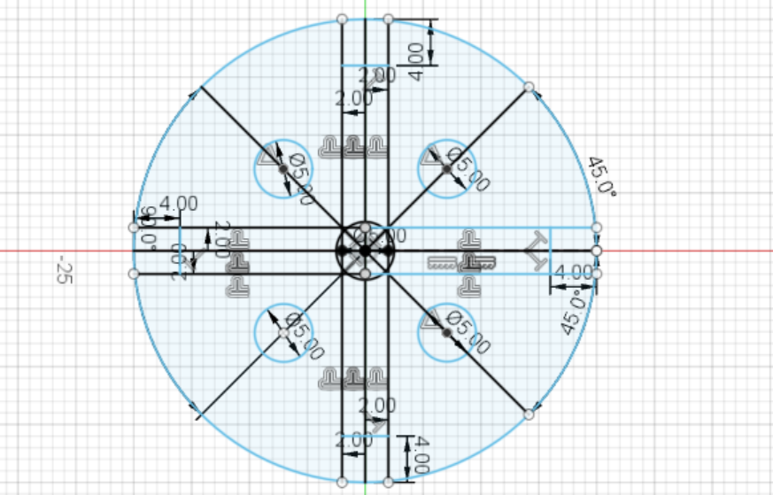
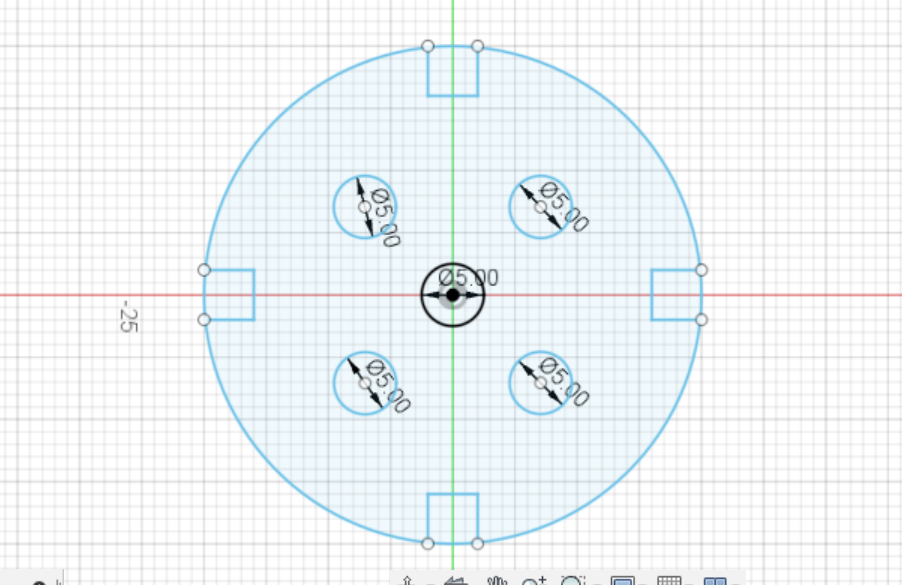
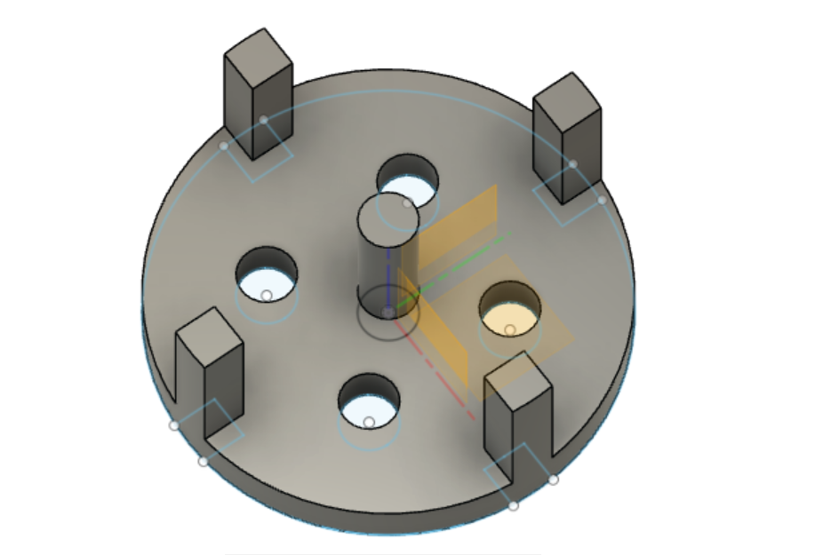
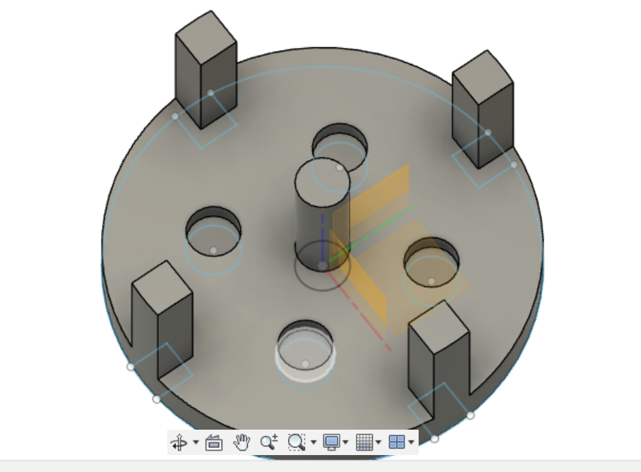
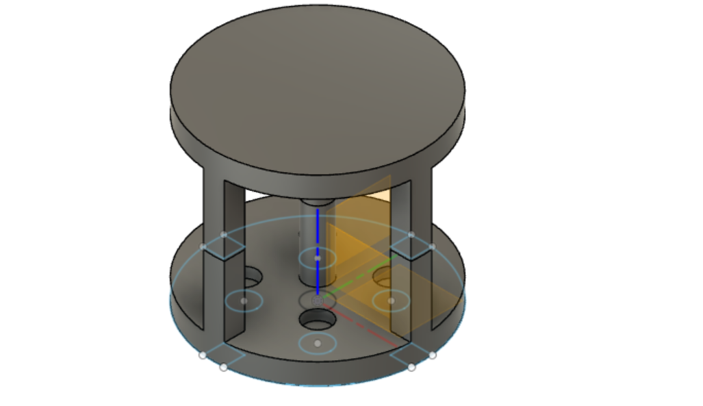
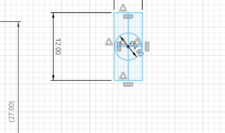
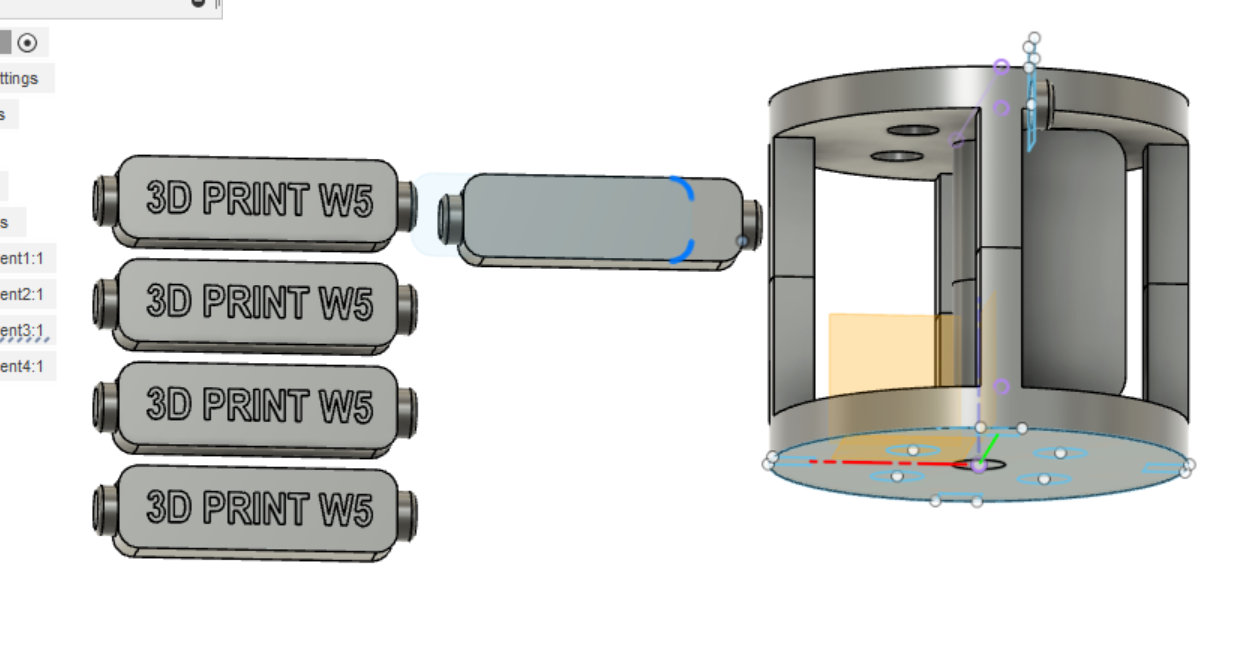
3D design was made in Fusion360 and the procedures are as given below.
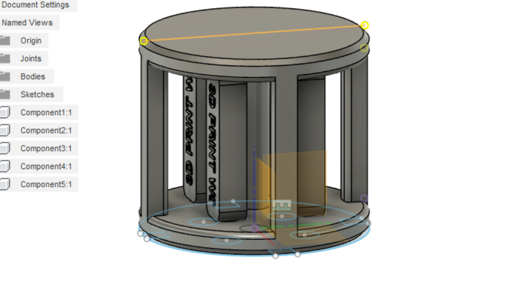
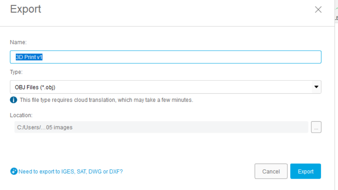
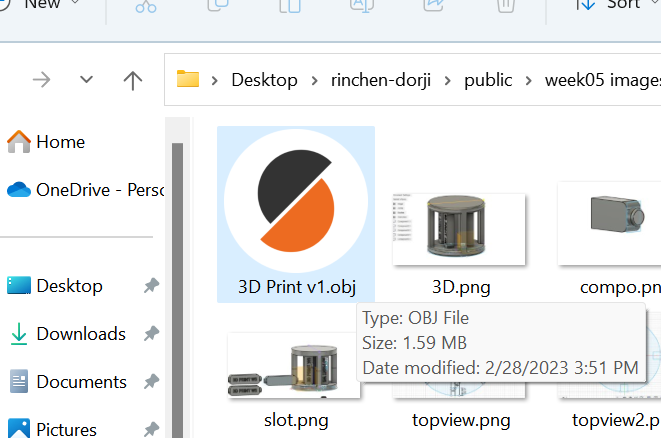
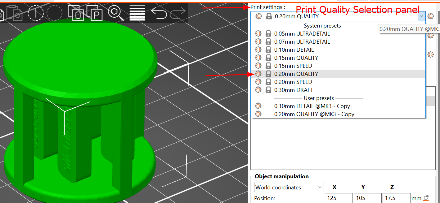
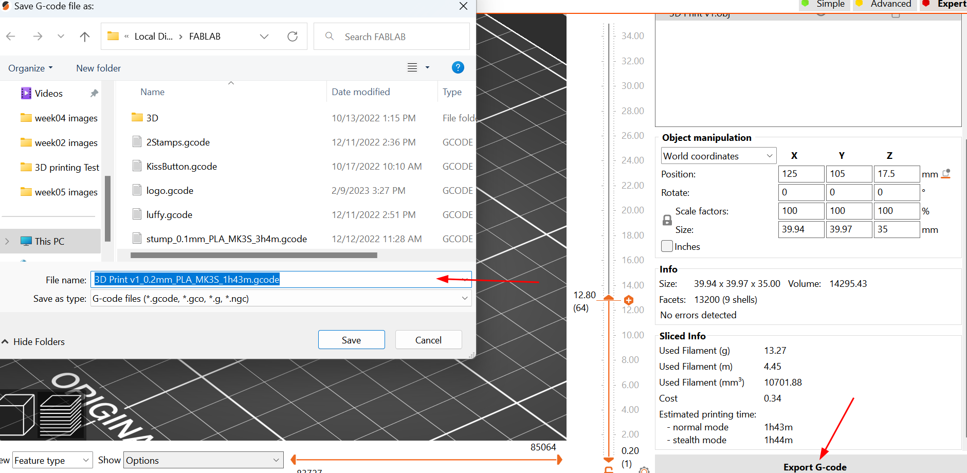
Design is completed, it is time to use this design file in the slicer to generate G-Code and also to check compatibility with the printing machine.
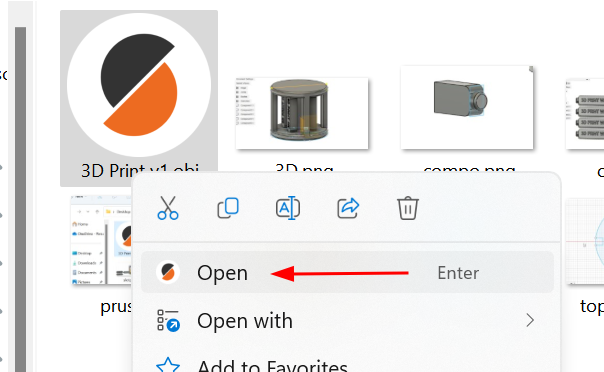
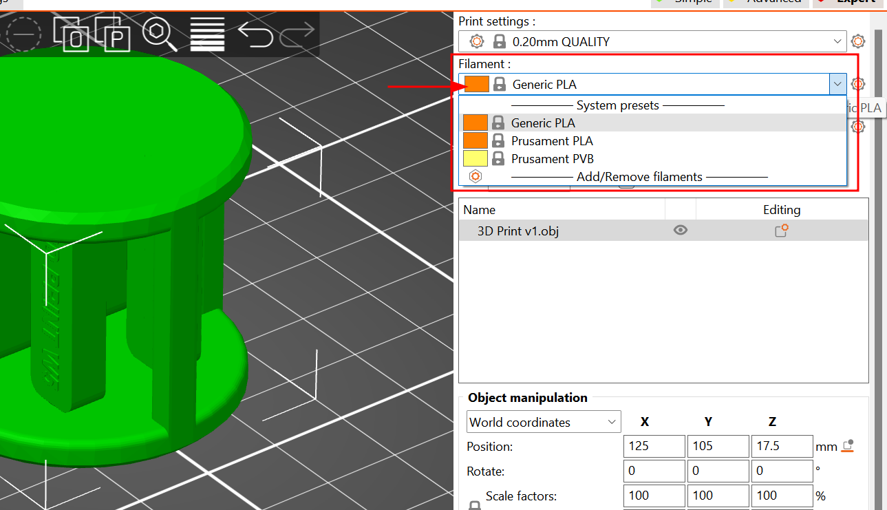
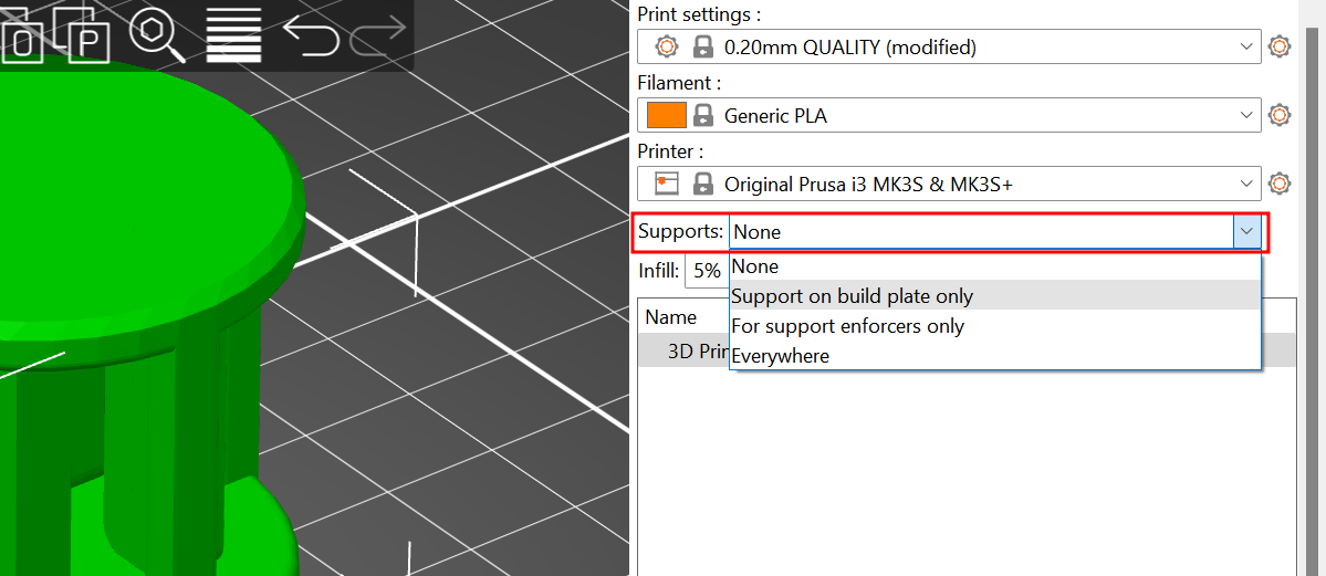
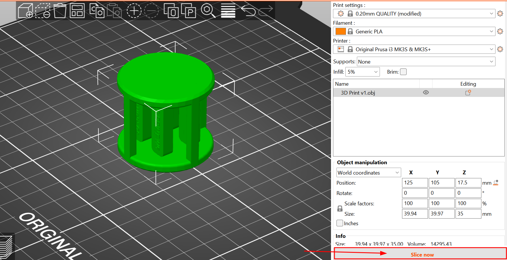
Using Prusa Slicer
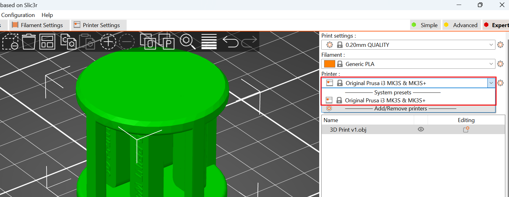
Useful Information
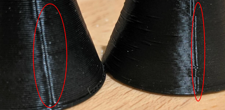
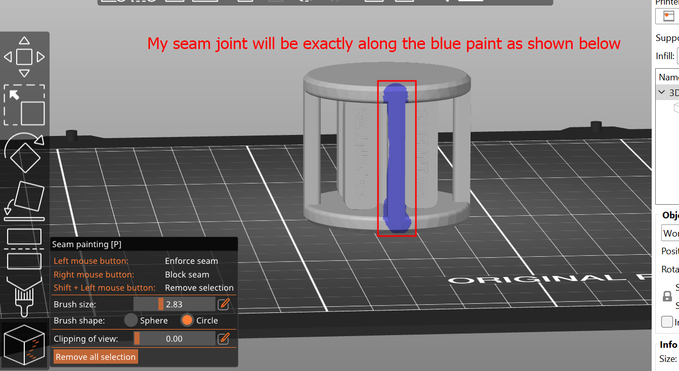
Z-seam
Z- seam is used to create a specific joint in one vertical line or as you desired (If not the joint in each layer will be distributed). Example given below is seam line and you can control that line on which face you want by drawing seam line as shown by next image.
None: tells your slicer to make no special preferences when choosing the starting point of a layer. Hide Seam: places the seam on the inner corners of your model. With the seam on the innermost corners of the model’s shell Expose Seam is the exact opposite of the previous one and places the seam on the outermost corners.
Cut option
The cut option allows you to print the object part by part if you really need bigger object which exceeds the total height of machine/(print area).After printing parts, you can join them with the help of glue and any paste material. Example as shown below:
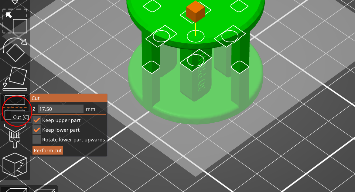
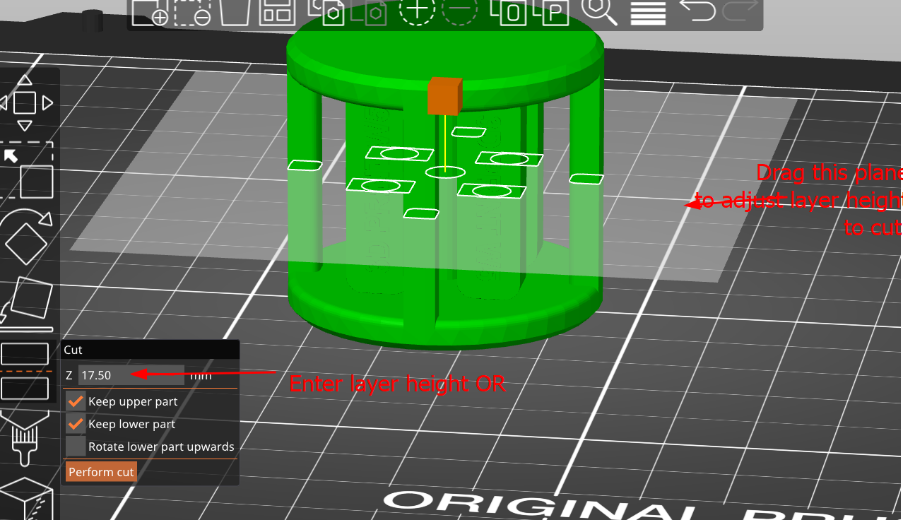
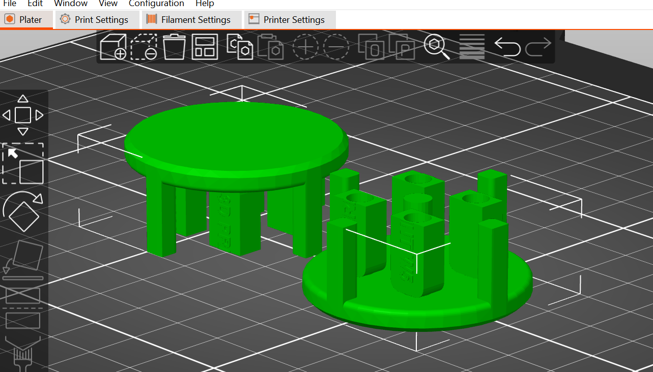
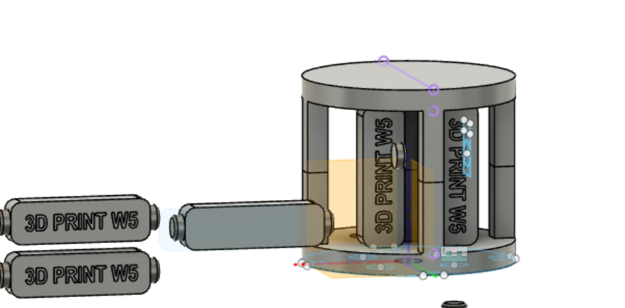
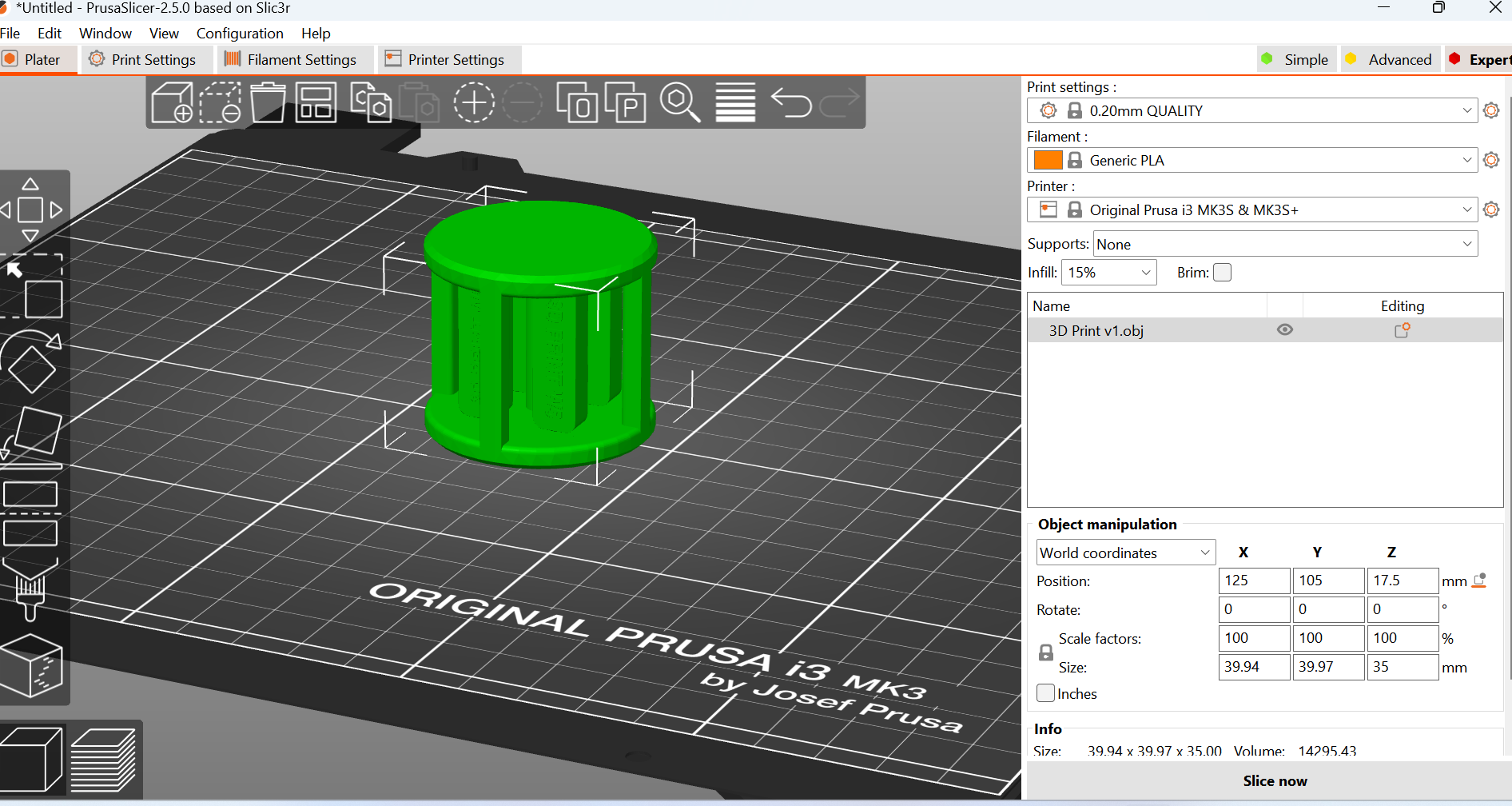
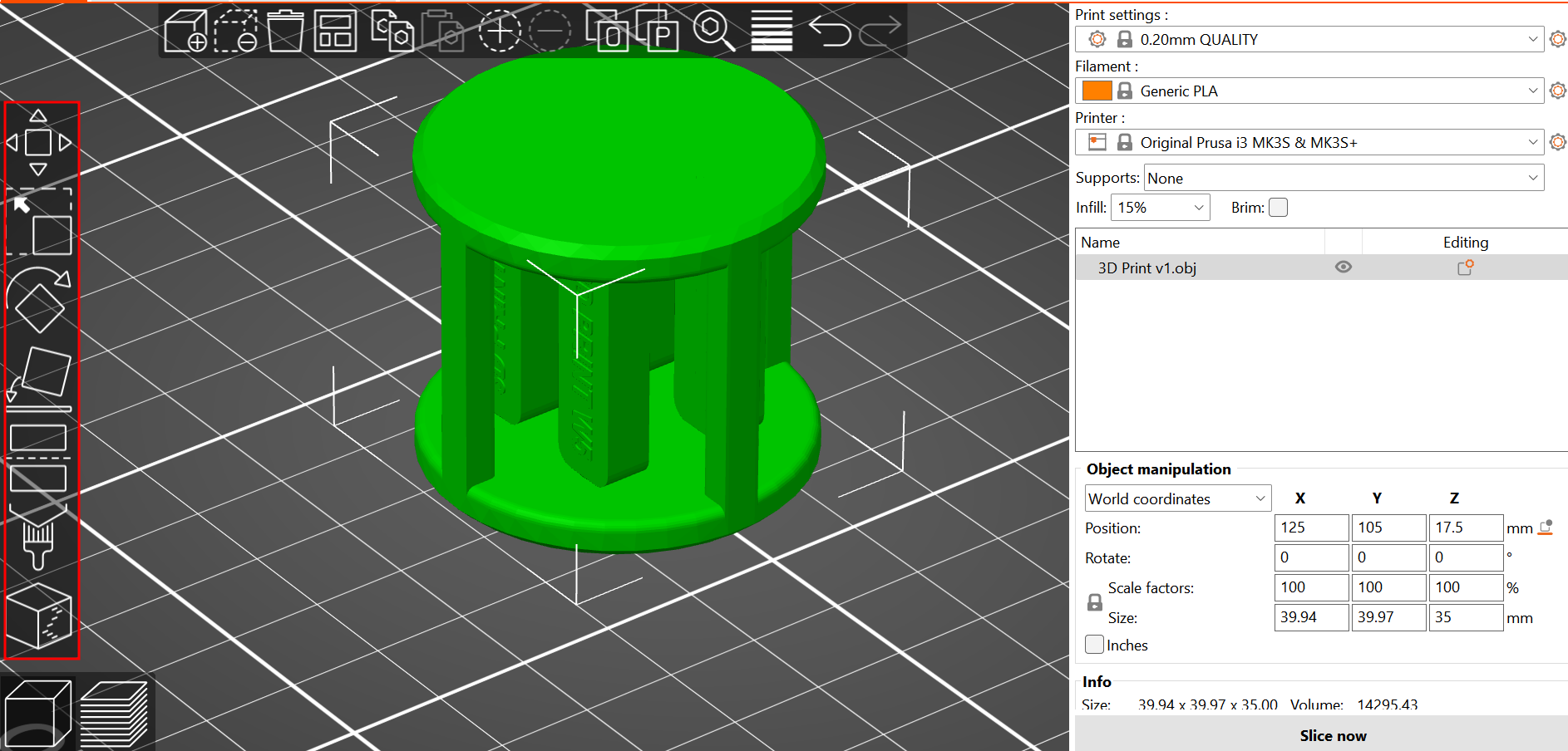
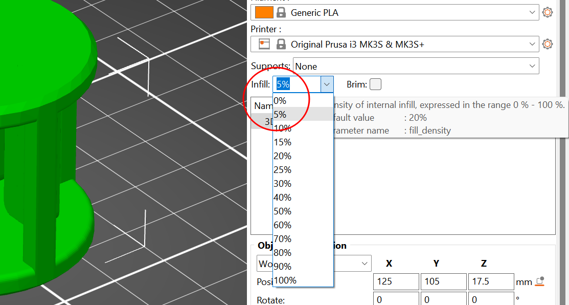
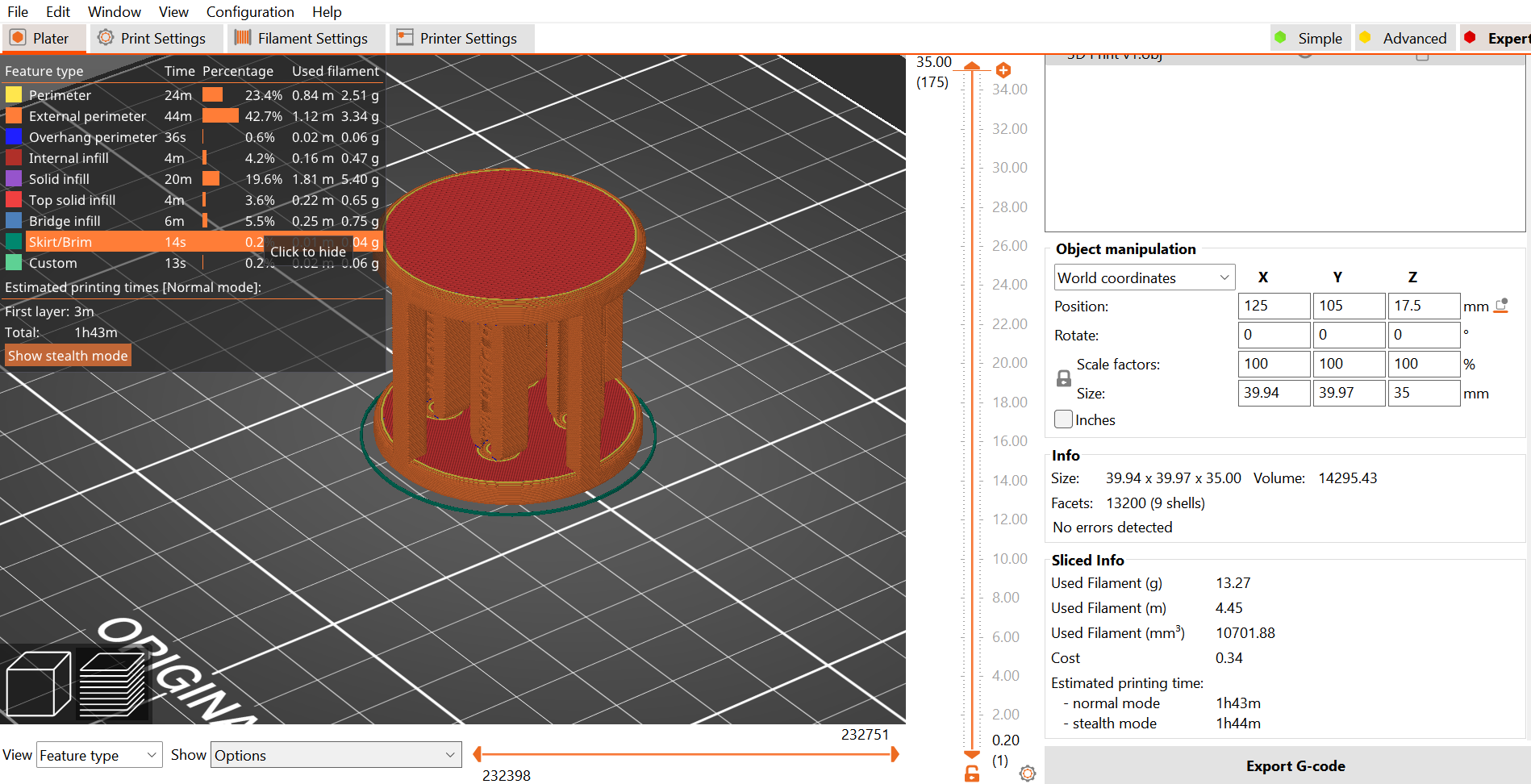
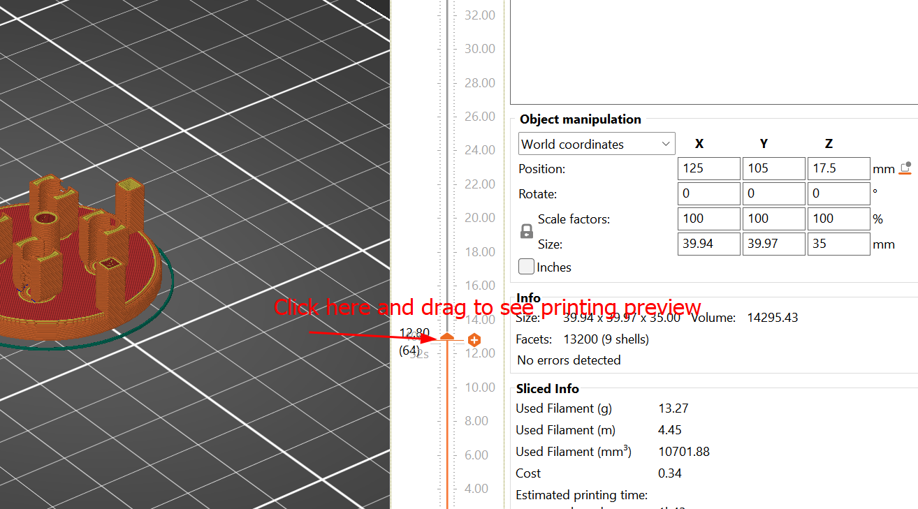
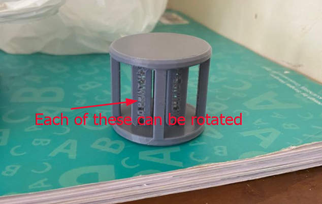
After perform cut, you can arrange the objects or hide one and print alternatively. My product is printed with 0.2mm layer height, no support, 5% infill and the product came out as given below:
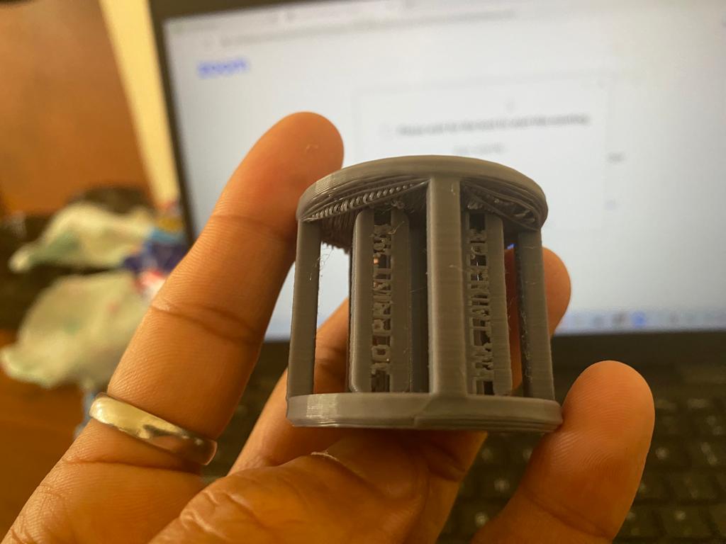
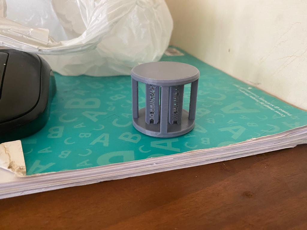
The individual components inside can be rotated freely, however, you need to remove some debris in between the axle and holder hole which is leftover from the support material. If you don't use support material in between then the individual components get attached to the base when printing. The individual component image as shown below and hero shot of the week.
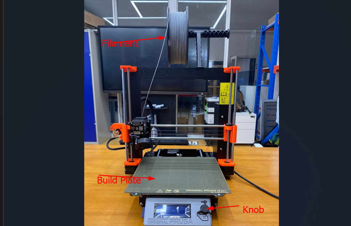
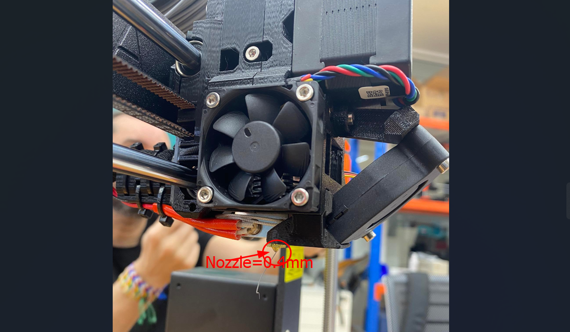
3D Printer and its parts
After inserting the disk in printer, rotate the Knob shown by red arrow to see options like drop down, press Knob to select your code. Filament is placed on holder and extruded through nozzle which gets printed on bed layer by layer. This process is additive manufacturing (Fused Deposition Method).
3D Scanning
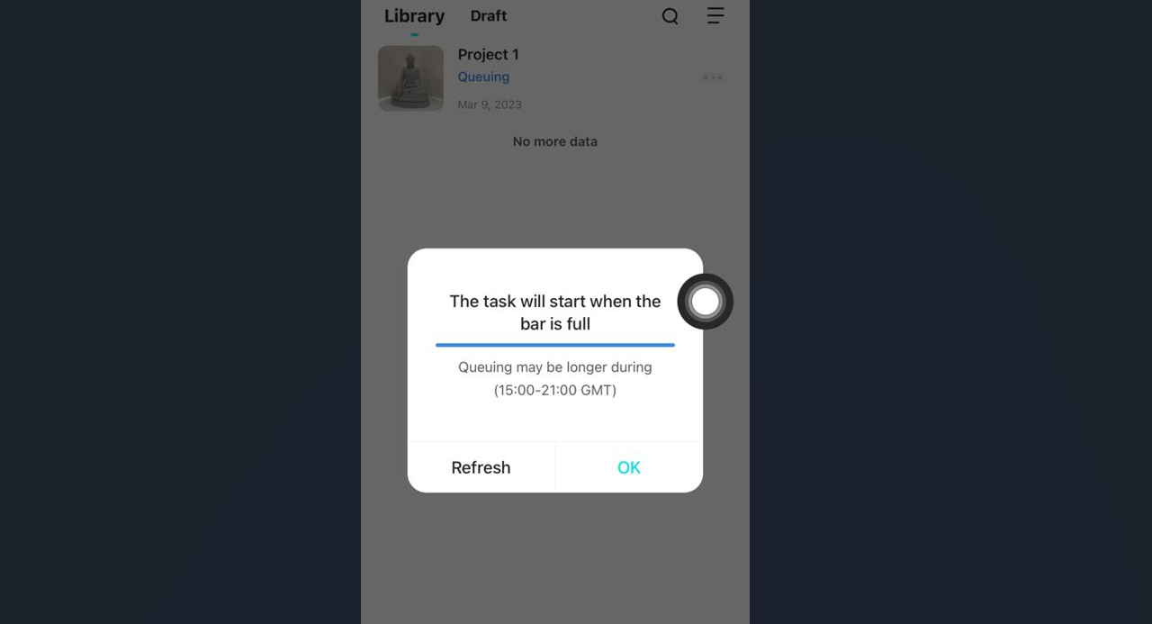
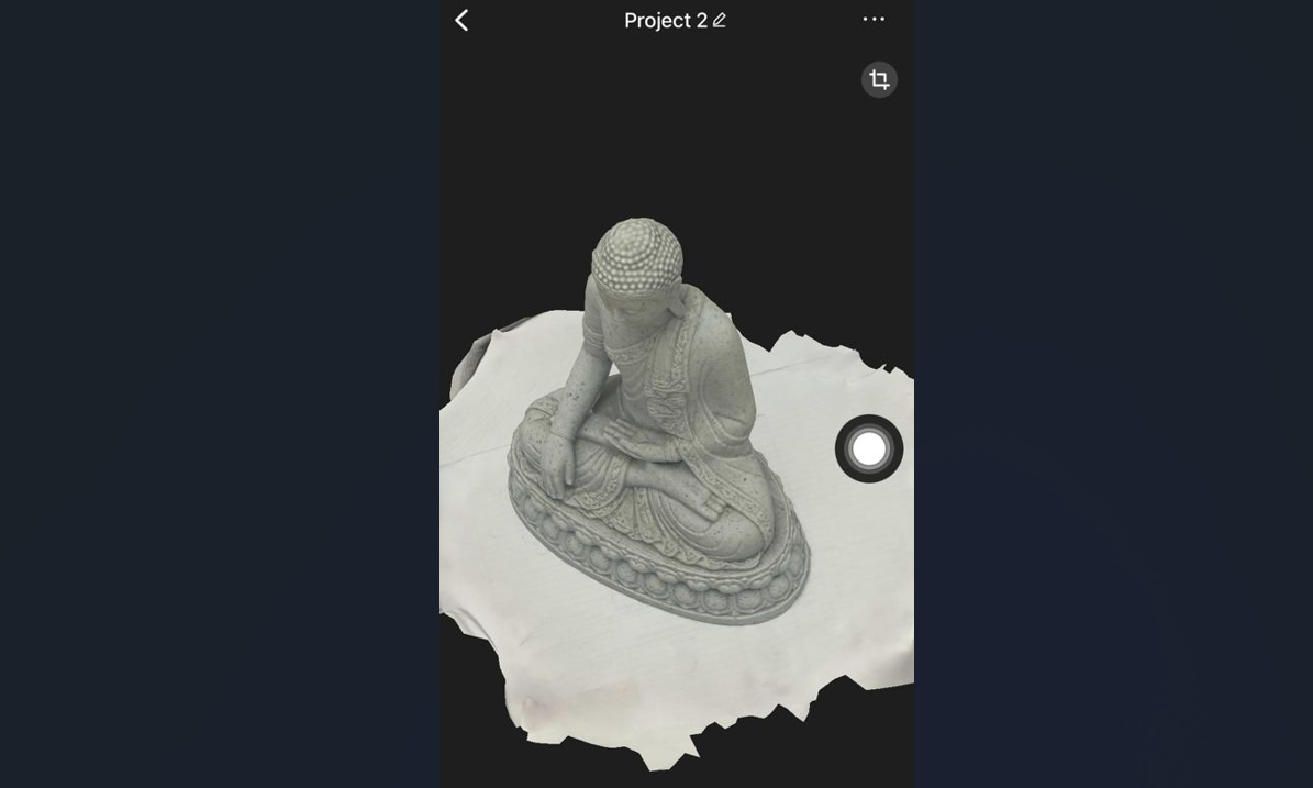
For 3D scanning, we were to install KIRI Engine on phone and use the app to scan complicated 3D objects. After this document. Therefore, I have installed KIRI Engine 3D scanner in my phone and used it to scan the Statue of Buddha.
Process of scanning and Creating 3D
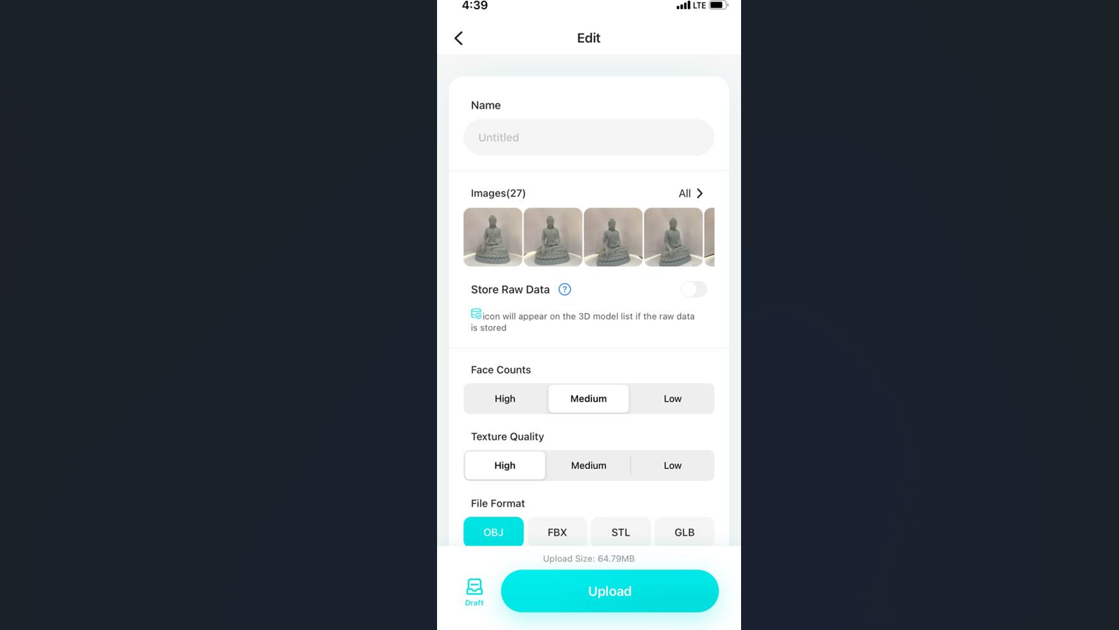
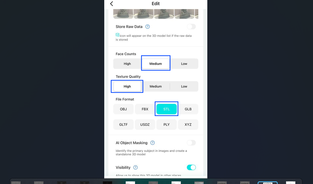
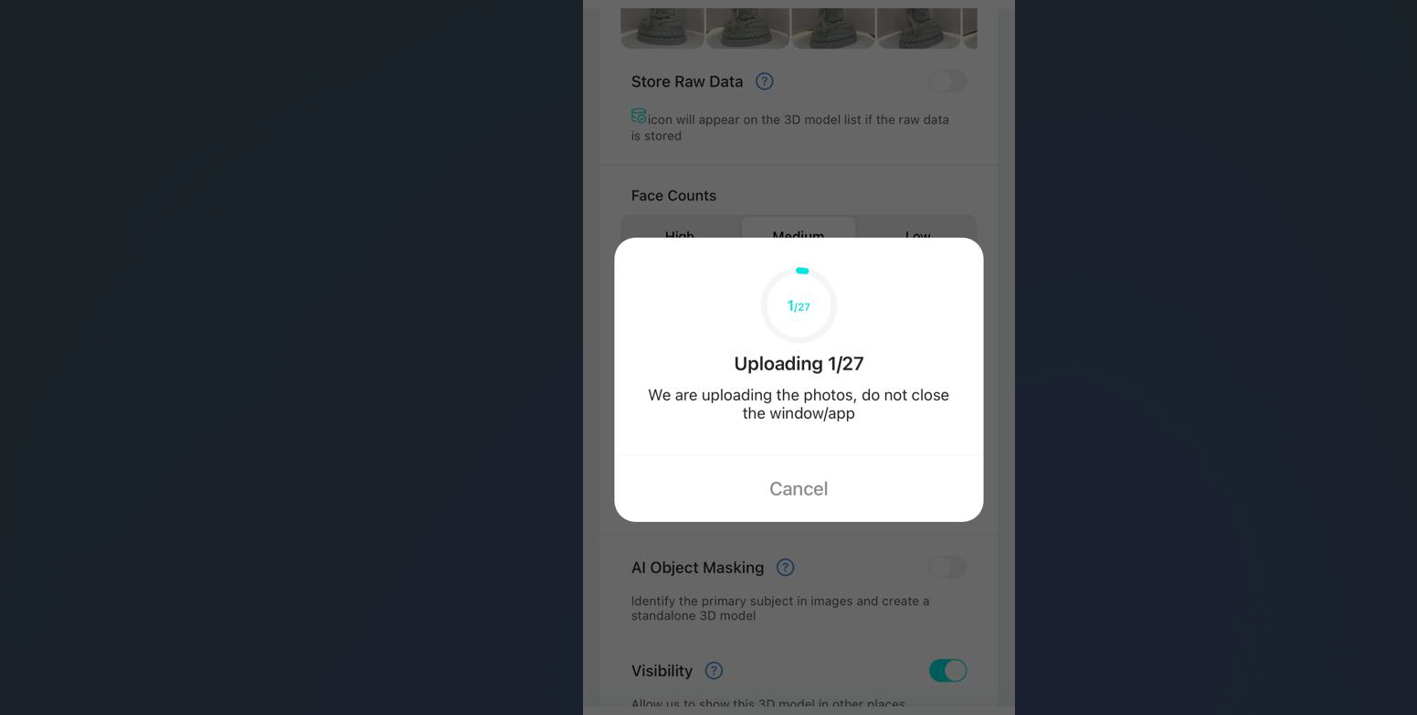
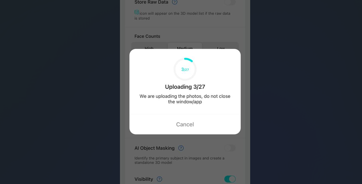
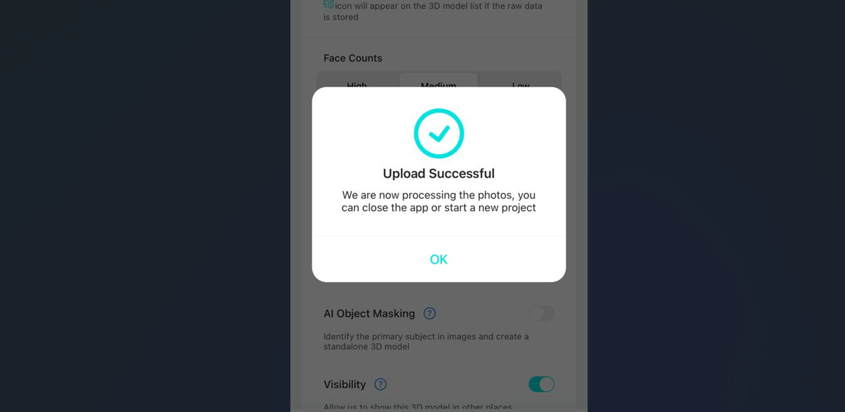
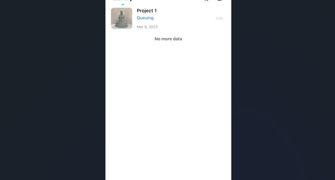
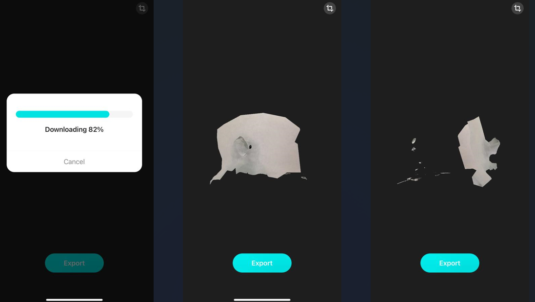
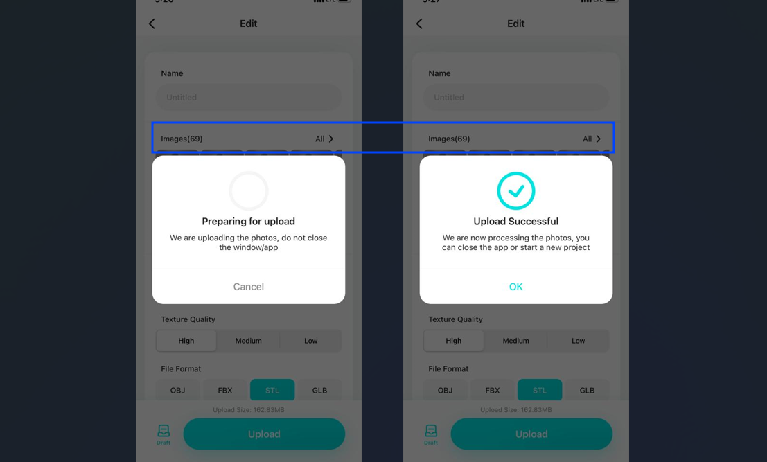
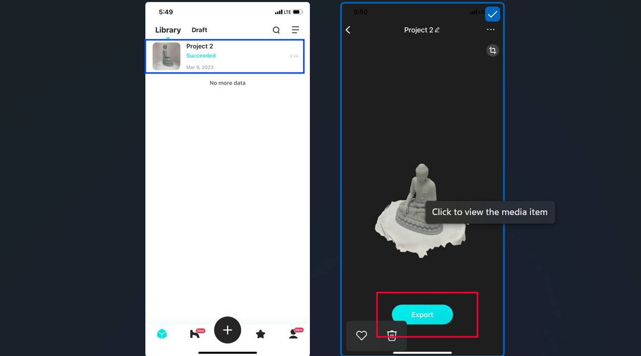
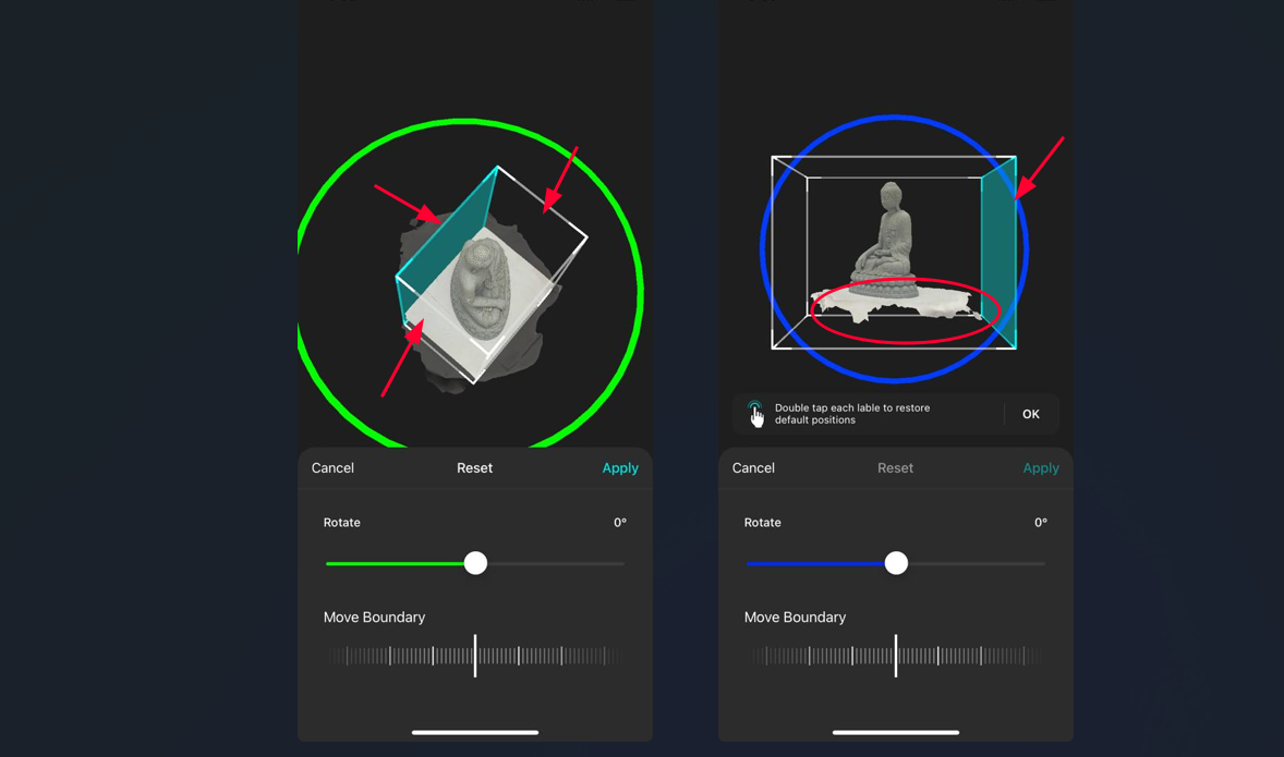
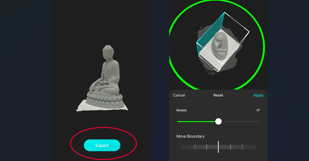
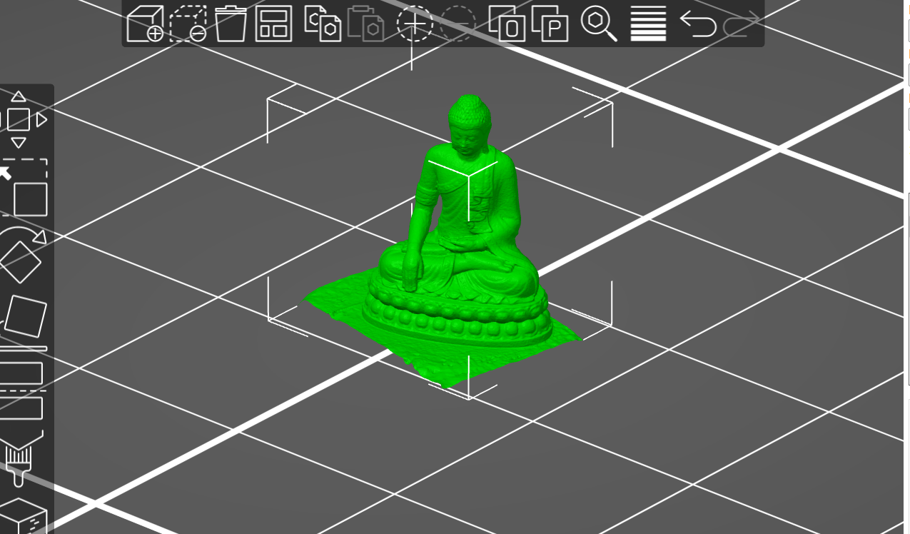
Now the 3D scanned model is ready to print.
Design Files
Designs Week 5