Embedded Programming
This week we got deeper into the FabAcademy course and I was curious to learn and explore about other areas. However, starting with embedded lecture I got nervous that there were many new terms and various components which I could hardly recognize. Moreover, being from mechanical background and moving into electronics was obvious to have doubts and this paradigm shift compelled me to research more. Despite all these anxiousness, I could gradually gain confidence with the help of peers and trainers.
Group Assignment
We only had developer kits for the Arduino Uno/Mega and the ESP32 in the lab so we were able to only compare the two.
Link to the group assignment: Bhutan FAB23 group
The experience was intriguing especially for having to learn completely new thing with an Arduino and also was dealing with an ESP32 for the first time. We worked with Arduino IDE for both (ArduinoUno&ESP32) so the workflow was almost identical apart from putting it together. I would like to learn more on ESP32 as I have come to know that it has got characteristics upper-hand over ArduinoUno however, as a beginner I prefer to go with Arduino.
Arduino
Arduino is a micro-controller. This small computer is used as the brain of the robot. It can be programmed to control the way buttons, motors, switches, lights, and other electronic parts work together. Arduino is hands-on, which is one of the many reasons it's appealing to tech gigs.
Arduino IDE
The Arduino Integrated Development Environment - or Arduino Software (IDE) - contains a text editor for writing code, a message area, a text console, a toolbar with buttons for common functions and a series of menus. Arduino IDE connects with arduino boards to upload programs and communicate with them.
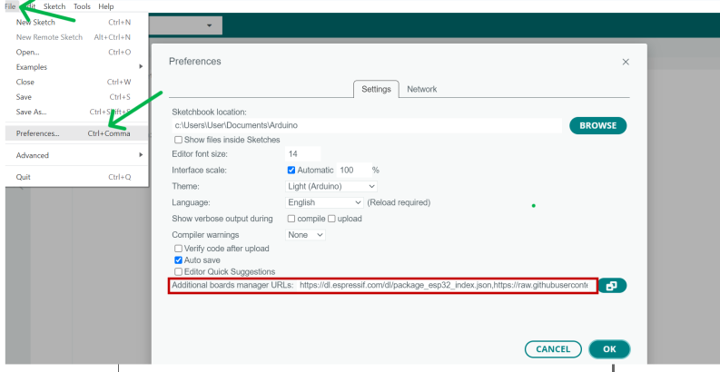
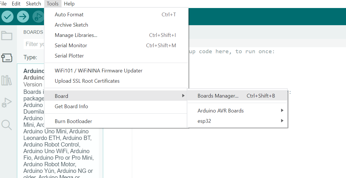
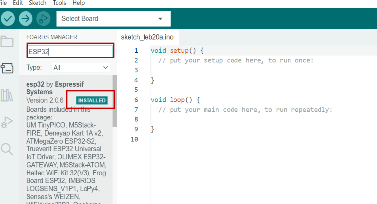
Procedures to set up Arduino IDE
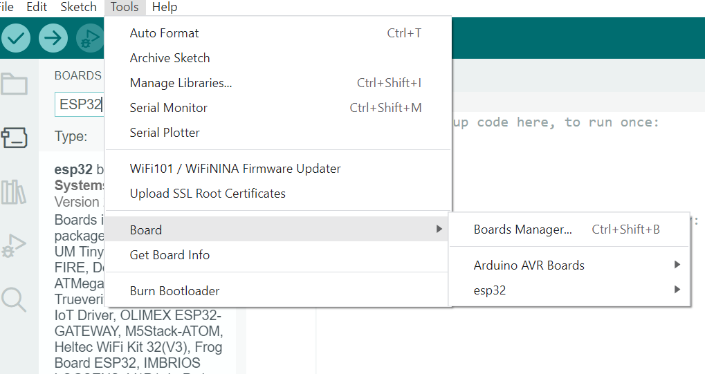
After downloading Arduino IDE, we have to add/download various kinds of boards like Arduino AVR, ESP32 etc in IDE. For this, we can do it from Arduino IDE by following the steps below:
Using Arduino UNO
Directly jumping into programming with Arduino was quite difficult task. Therefore, Ms. Zina recommended us to use TinkerCAD circuits in which you can make the circuit boards and generate the code which can be used to code in Arduino IDE. TinkerCAD circuit has the capacity to simulate the circuits boards after connecting all the components for confirmation. At first, we were asked to connect LED bulb with resistor and conduct blink test and we did series of other operations after this.
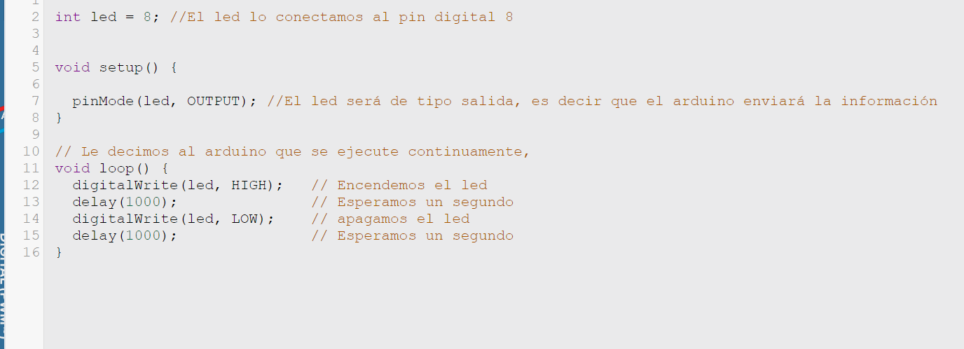
For this blink test, the code I generated from TinkerCAD circuit was like given below:
After successfully simulating in the TinkerCAD circuit and generating code, I used the code in Arduino UNO to conduct the blink test from my computer. After copying the code, you just need to verify >> and then upload.
Also tried playing with servo motor for more hands on practice.
Programming was intimidating at first but as we continued working on, it was interesting and I have learned to code with the help of Chat GPT. Most of the codes were generated from chat GPT and were accurate.
Connections and Learnings
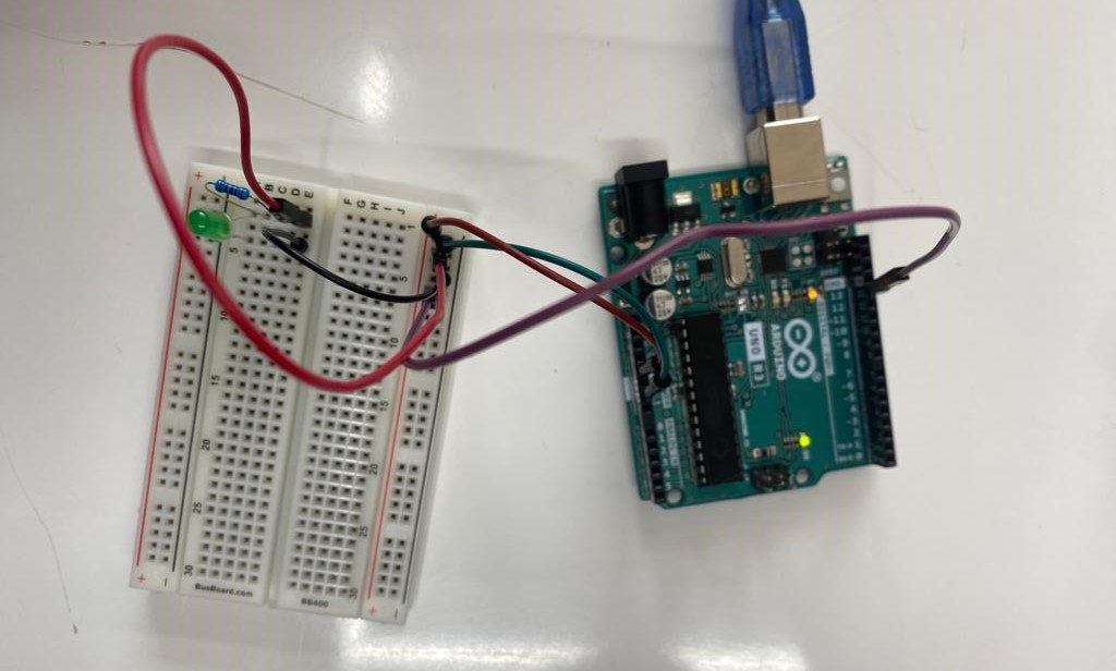
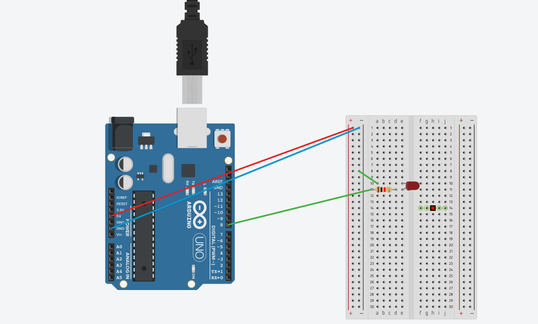
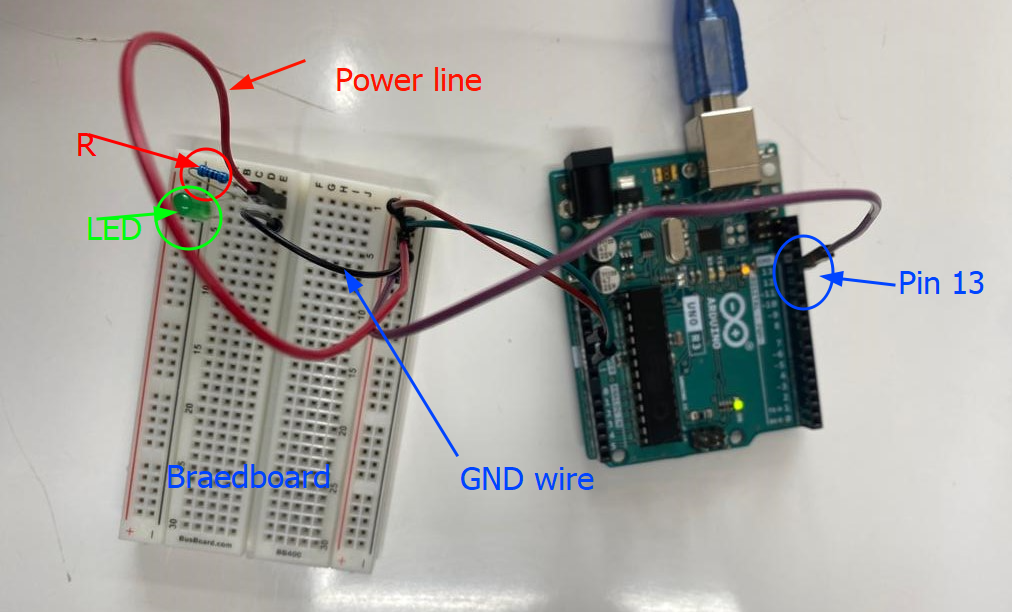
For the blink test, we used LED and it has got two ends which is Anode (A) and Cathode(C), usually their ends are represented by Anode being longer leg and cathode the shorter one. Anode is connected to oin 13 on arduino end which is power line and cathode to GND (Ground) which is used as earthing. Wires are differentiated by red being the power source line and black for grounding and LED is the load. Before power line to Anode, resistor is used in between to protect the LED from getting burned/blown as the power source from arduino was 5V. Image below holistically describes the connection details:
Reading DATA sheet
ATmega 328/P
Reading data-sheet was completely new thing and I was lost. However, after some tips from Mr.Rico about what and how to read, I got some idea and the following are what I have found.
Some tips suggested by Mr.Rico are:
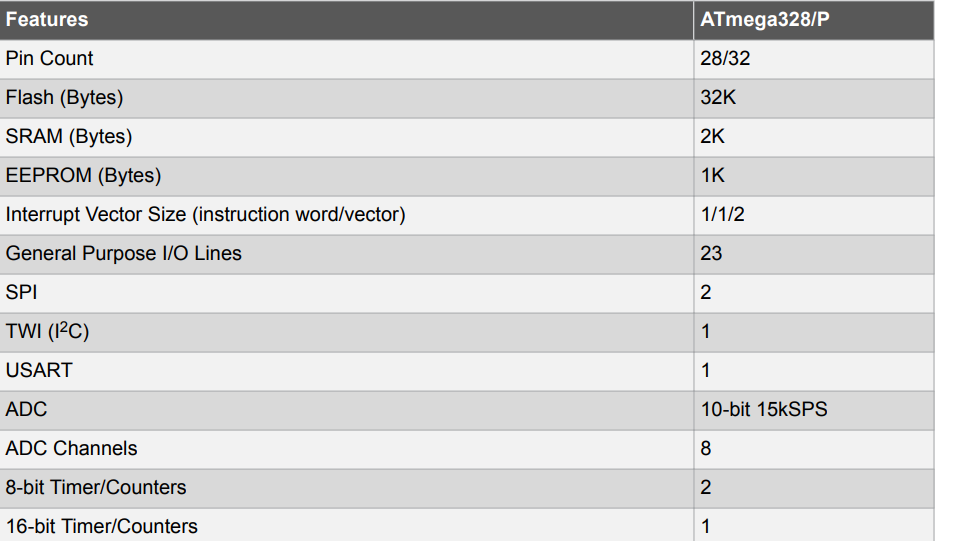
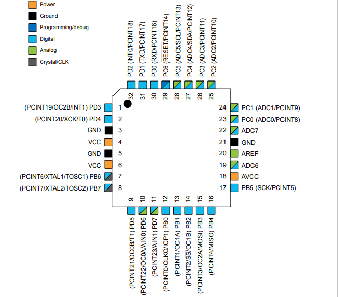
With these many questions provided by Mr.Rico I skimmed through data-sheet of micro-controller ATmega 328/P and also Learning About Electronics. The first thing I learned was micro-controller is referred to as MCU and it has got RISC (Reduced Instruction Set Computer-meaning a microprocessor with simple collection and highly customized set of instructions) structure with a clock speed of 8Mhz Mhz-MegaHertz (Clock speed meaning-measures the number of cycles your CPU executes per second). Actually I found that ATmega 328 P has two internal oscillator from which one clocks are 8Mhz and other at 128kHz. ATmega 328P have 3 types of memories 1. Flash Memory (meaning memory which can store data and quickly) 32KB programmable Read-Only Memory and non-volatile (This means it receives data and permanently writes it on a chip, and it lasts even after you turn off your computer). 2: SRAM (Static Random Access Memory) 2KB: meaning-retains data bits in its memory as long as power is being supplied. 3: EEPROM: 1KB:Electrically Erasable Programmable Read-Only Memory meaning is a user-modifiable ROM. It can be erased and reprogrammed. ATmega 328P comes with 32 or 28 pins and 23 GPIO (General Purpose I/O lines/pins-This means they can function as an input to the circuit or as output). 14 pins are digital pins (pin numbers are: 2(PD0), 3(PD1), 4(PD2), 5(PD3), 6 (PD4), 11(PD6), 12(PD7), 13(PB)), 14(PB1), 15(PB2), 16(PB3), 17(PB4), 18(PB5) and 19 (PB6). Among these 14 pins 6 can function to give PWM (Pulse Width Modulation-used control technique that generates analog signals from digital devices such as micro-controllers) output. 6 Analog pins they are 23(PC0), 24(PC1), 25(PC2), 26(PC3), 27(PC4), and 28(PC5). 2 pins for crystal oscillator to provide a clock pulse for the Atmega chip. For power purpose 2 pins, VCC-Voltage common collector and GND-ground. I came to know that the Atmega328 is a low-power chip, which requires only between 1.8-5.5V of power to operate. Other features include Micro USB programming and power supply,ISP Header,3 on-board Grove connectors for better prototyping.
Communication Protocol of MCU
From Google I found out that the Protocol Serial Peripheral Interface (SPI), Inter- Integrated Circuit (I2C), Universal Asynchronous Receiver / Transmitter (UART), Controller Area Network (CAN) and Universal Serial Bus (USB) are ideal communication protocols which people use for communication between microcontrollers
Feature
High Performance, Low Power Atmel®AVR® 8-Bit Micro-controller Family
- Advanced RISC Architecture
- -131 Powerful Instructions
- -Most Single Clock Cycle Execution
- -32 x 8 General Purpose Working Registers
- -Fully Static Operation
- -Up to 20 MIPS Throughput at 20MHz
- -On-chip 2-cycle Multiplier
- -Operating Voltage (1.8 - 5.5V)
- -Temperature Range (-40°C to 105°C)
Configuration Summary
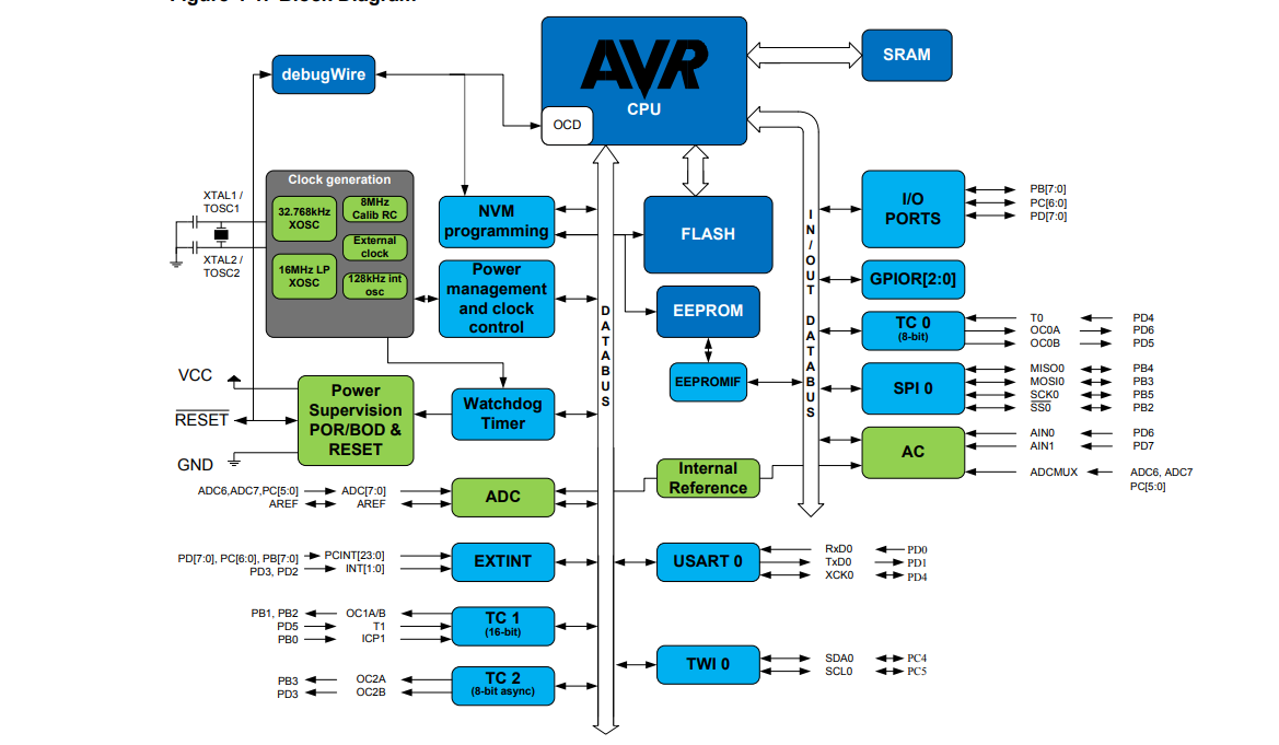
Block Diagram
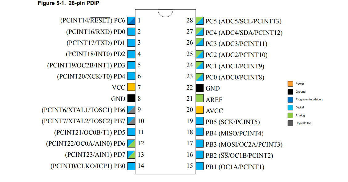
Pin Out 28 Pin
Pin Out 32 Pin
Codes Embedded
Examples of code for Blink Test connecting Anode of Led to Number 13 of Arduino board is shown below for reference.
      // Set the pin number where the LED is connected
int ledPin = 13;

void setup() {
  // Set the LED pin as an output
  pinMode(ledPin, OUTPUT);
}

void loop() {
  // Turn on the LED
  digitalWrite(ledPin, HIGH);
  // Wait for 1 second
  delay(1000);
  // Turn off the LED
  digitalWrite(ledPin, LOW);
  // Wait for 1 second
  delay(1000);
}
The code for the blink test Codes of blink test, 3LEDs , Servo motor