Computer Controlled Cutting- Laser Cutting & Vinyl


Group Assignment


In this week we were also given group task with characterization of laser cutter and kerf and clearance calculation. In this group work, every individual participated in setting parameters of machine, loading workpiece, calculating clearances and kerf. Assigned one photographer and Mr. Thinley documented mostly. To access follow this link Bhutan FAB23 group.

Computer Controlled Cutting is process of cutting or engraving by a machine based on computer-controlled parameters. There are various machines which can perform the operation however, for third week of FabAcademy we specifically focussed on two machines that is 1.Vinyl Cutter and 2.Laser Cutter.


Vinyl Cutting Machine - Roland GS-24 CAMM-1


                                                Roland GS-24

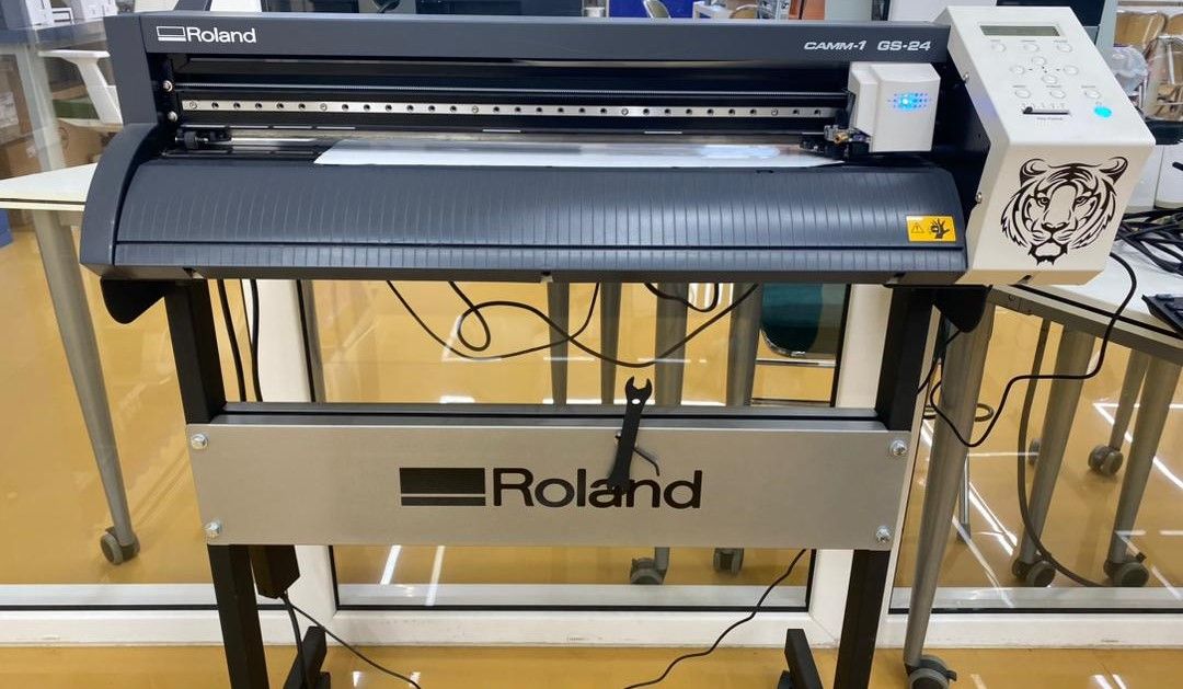
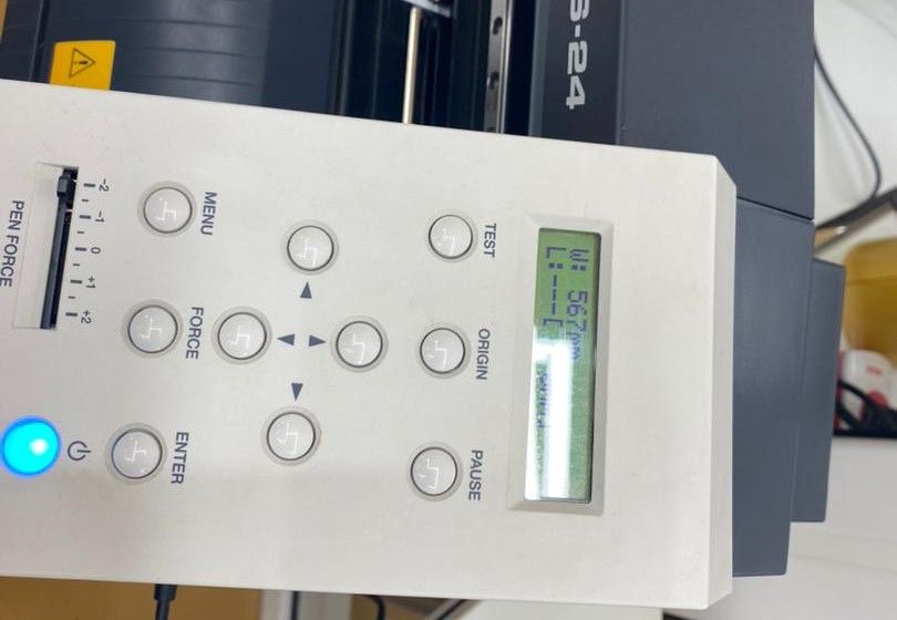
We started using vinyl cutting machine Roland GS-24 CAMM-1 at JNWSFL with pre-requisites and safety measures to be followed by Ms.Zina. We look into safety aspects of both man and machine. The Lab has to be clean and free of dust. Computer designed vector files with patterns and letters are directly cut on the roll of vinyl which is mounted and fed into the vinyl cutter through USB or serial cable. Vinyl cutters are mainly used to make signs, banners and advertisements.


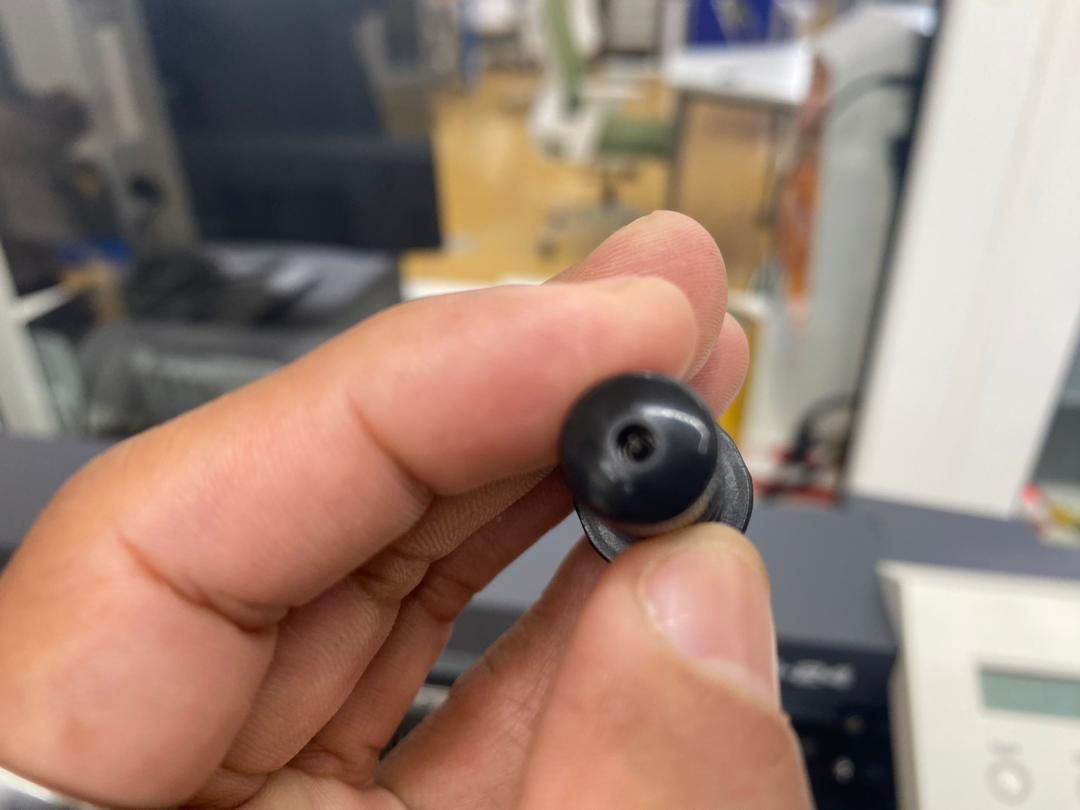
Checking Cutting Tool


Check if the tip of cutting tool is pointed and sharp. For the fine cuts and high speed operation the tip should be sharp and pointed. Generally, the tip of tool is 45 degree universal.


Using Vinyl Cutting Machine to cut stickers


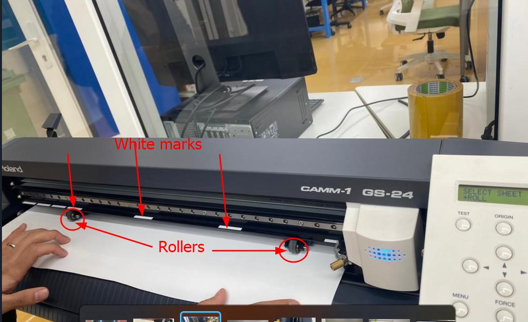
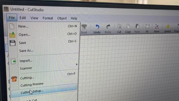
Before getting into using machine, its set up is very important. Parameters like checking the blade, clamping the vinyl within the rollers and keeping rollers on the white mark.


Set Up Procedures


  • 1.Vinyl Setting:Place the vinyl in machine in machine table. The vinyl has to be held with *roller* and those rollers has to be on *white mark* on machine table.
  • 
          
                                                   Vinyl Alignment
    
           
  • 2.Cutting tool set up:The cutting tool is fixed in it's holder. Cutting tool has to be covered with its cover and it has to just enough to feel with your finger. *The point of the tool*.
  • 
          
                                                   Cutting Tool Point
    
           
  • 3.Checking tool if it is ready to use:The point of the cutting tool has to be just enough to cut the thickness of vinyl. For that you can conduct test which is default setting in machine.
  • 
          
                                                   Cutting Tool Test


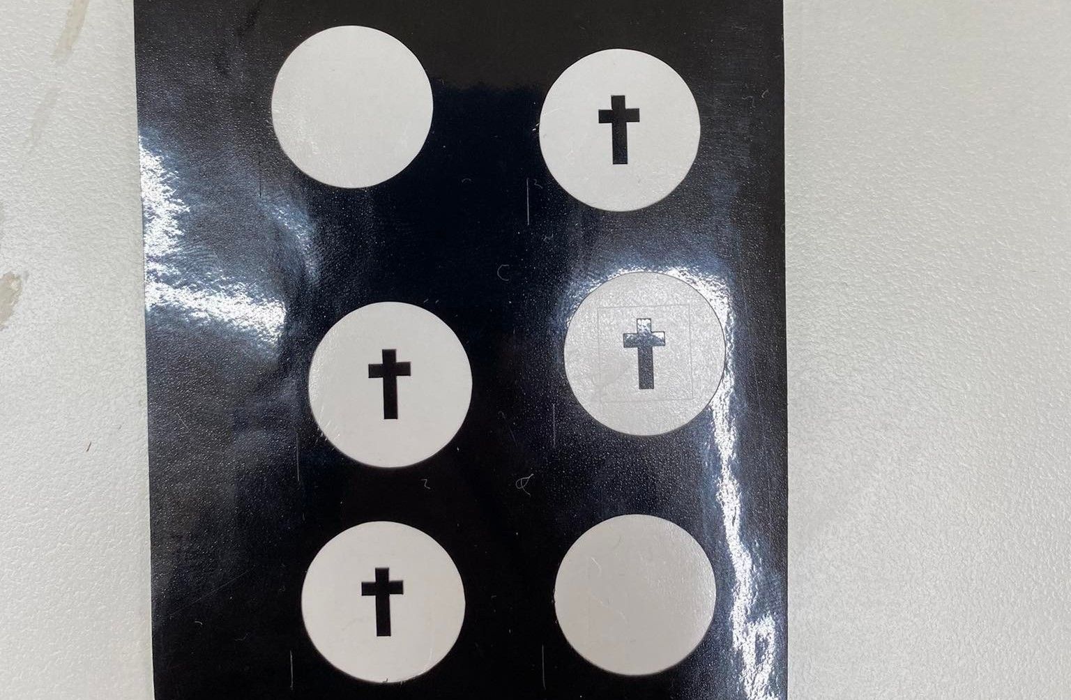
    This image is to perform test of cutting tool set up. It consist of circle, square and cross mark and when you test run machine after fixing tool in spindle, you'll have to remove circle, then square and cross mark should remain. If any of other marks get removed when removing respective cut-marks then the tool set up is not correct, therefore tool setting has to be done again. Either you keep tool longer or shorter by rotating its cover by *one mark*.


    Basic Commands


                                                    Basic Commands of VinylCutter
    
          
  • Roll:measures width of vinyl
  • Edge:takes cutting tool position to starting point
  • Piece:used when the vinyl is of short and small piece to measure width
  • Origin Set:Press and hold this command to set origin of the cutting tool
  • 


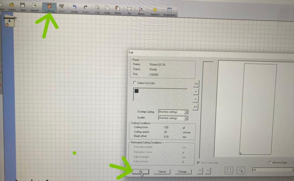
    Steps to Cut Stickers or Others


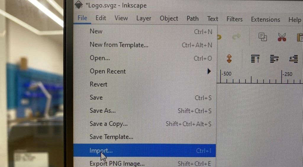
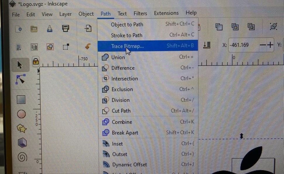
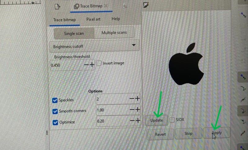
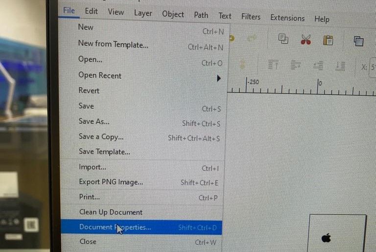
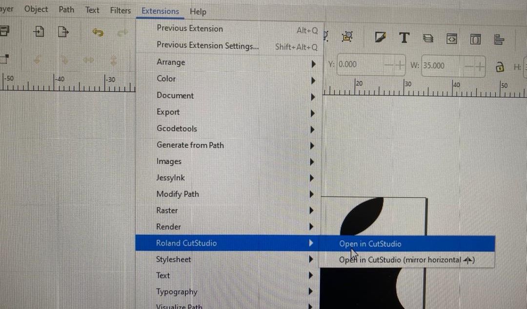
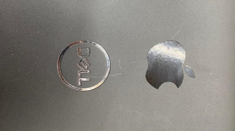
    For this, we were asked to use any raster image from online and edit in inkscape to vectorize, then cut using vinyl cutter.

  • 1. Download any raster image from google and save.
  • 2. Open Inkscape and choose new document.
  • 3. Go to file and then Click on import.
  • 
          
                                                    Importing File
    
          
  • 4. Choose the file you downloaded and your image appears in working window.
  • 5. Go to path and then Trace Bitmap as shown below:
  • 
          
                                                    Tracing Bitmap
    
          
  • 6. Click on update and Apply as shown in image below:
  • 
          
                                                    Vectorized
    
          
  • 7. Click on the image, hold and drag. There will be two images and one is vectorized. Zoom in to see if you cannot see the difference and one which gets blurred when zooming is raster and delete that one.
  • 8. Go to file and then Select "Document properties" OR use short cut key Shift+Ctrl+D.
  • 
          
                                                    Document Properties
    
          
  • 9. Click on Resize page to content as shown in image below by green arrow.
  • 
          
                                                    Resizing Image to content
    
          
  • 10. Set the margins 5mm in all corners to make sure that your image is safe to cut. OR insert margin in one corner and click on lock button to update in all corners equally.
  • 11. Then click on resize page to drawing selection and then your image and paper size appears with 5mm margin. Now it is ready to be cut using machine.
  • 12. Go to Extensions then Roland CutStudio and Open in CutStudio as shown:
  • 
          
                                                    Using CutStudio
    
          
  • 13. Go to file and Cutting set up
  • 
          
                                                    Cutting SetUp
    
          
  • 14. Change the power or keep as default which is 120 and click on get from machine.
  • 15. Go to Cutting and Click on OK as indicated by green arrow mark, your image will be cut now.
  • 
          
                                                    Cutting SetUp


    Post Processing


  • STEP1: Stop the machine and turn off power.
  • STEP2: Cut your image which is cut by machine with scissors or cutter.
  • 
          
                                                    ImageCut
    
          
  • STEP3: Remove unwanted parts with tweezers if there are fine details in your image. (Weeding)
  • 
          
                                                    Weeding
    
          
  • STEP4: Use transparent sheet and cover over your image carefully ensuring no air bubble gets trapped inside.Or use other object such as shown to perfectly paste transparent sheet to your image.
  • 
          
                                                    Using Transparent sheet
    
          
  • STEP5: Now peel your transparent sheet and your image gets attached to transparent sheet.
  • STEP6: Now paste your image with transparent sheet on the object that you want your sticker to be on, keep for sometime and then remove sheet. Note: Clean your object surface with colin before pasting sheet on it and when you remove carefully do it to shear not lift up as show below.
  • 
           
                                                    Removing Transparent sheet


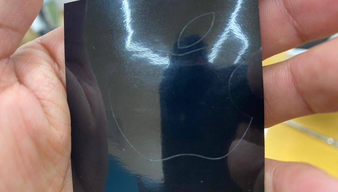
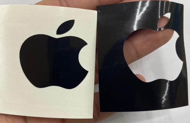
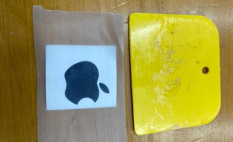
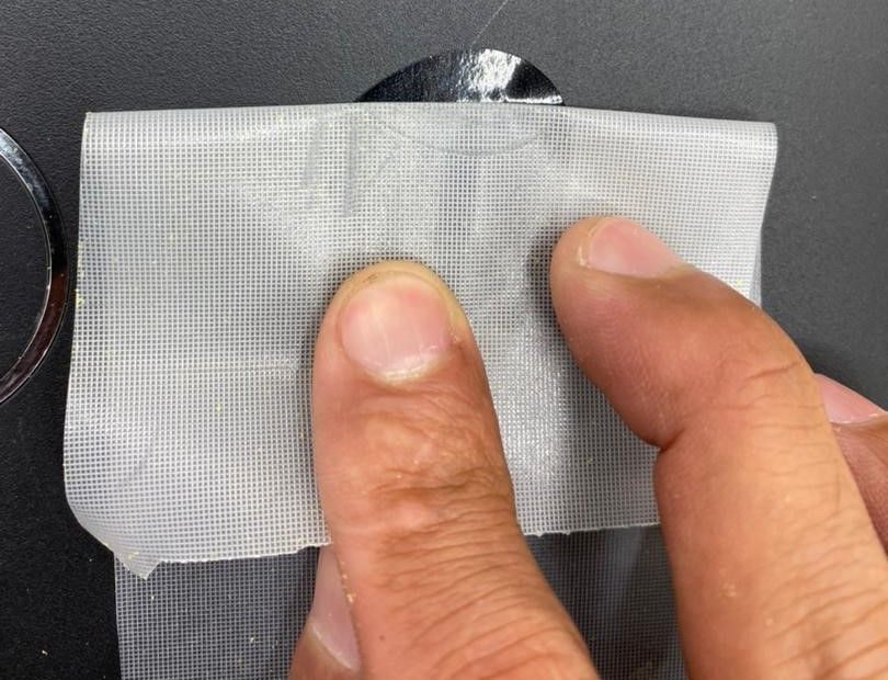
    Now you passed using vinyl cutting machine and my final sticker (an apple logo) is pasted on backside of laptop


                                                    Removing Transparent sheet


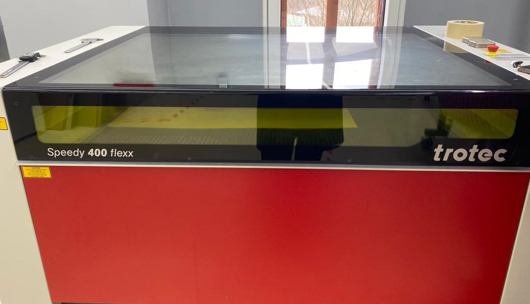
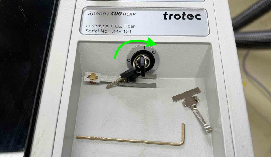
    Laser Cutter- Trotec Speedy 400 flexx (CO2, Fiber)


                                                     Laser Machine


    Safety measures to be followed when using laser cutter is critically crucial because this is the machine that can be catastrophic if gone wrong because it can cause fire. When operating this machine, operator should be vigilant and should be knowing the material to be used. Therefore, some basic and critical information to keep in mind:

  • Laser cutter cuts the job path by burning
  • Plastic material cannot be used as it will melt
  • It releases corrosive gases
  • It is safe to know the job material before cutting
  • Dust particles will propagate to smoke which might burn lens
  • CO2 laser for glass and wood engraving (aluminum and SS can be used)
  • Use exhaust system with machine
  • Fibre laser used for metal engraving
  • 


    Safety of Machine


  • Job material selection is important
  • Exhaust system should be running
  • Use air blower before operation to remove dust particle from tool path
  • Keep the cover closed until all the smoke or gases inside bed is disappeared
  • After certain time the space below bed gets filled with particles, therefore remove those by vacuum cleaner
  • ***Note: Always remember to keep eye on machine when running the machine and cannot leave machine unattended***


    In event of fire


  • Press emergency brake (first step is to stop machine by emergency braking)
  • If fire continues after braking, open the cover and push the beam holder to side and remove job and try to put off fire
  • If the flame is already large, use blanket to cover job and put off fire ( or also use water to put off fire after taking out job from bed)
  • In case of Machine burn use fire extinguisher
  • Call fire department if the incident goes out of control
  • 


    How to Avoid Fire?


  • Setting of the machine operation has to be 100% correct
  • Job material selection is correct
  • Setting basically consist of 1. Speed 2. Frequency 3. Power
  • Or test run the machine before operation with power of 10 and speed of 100 for any kind of job material. (You can also set standard setting board in your local lab for easy preference in future).


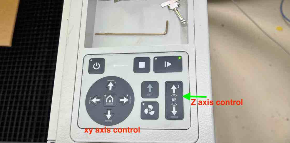
    Operating Laser Cutter and Controls


  • 1: First turn on the machines power source and then turn the knob to the right and you will hear the sound
  • 
          
                                                    Starting Machine
    
          
  • 2: Ensure the lid is closed. During initialization. You can open the lid after a beep is heard once the machine is done homing and starting up.
  • 3: Open the Lid and place the job piece in the workspace(Machine bed). Place it at the origin 0,0 which is at the top-left.
  • 
          
                                                    Placing job piece
    
          
  • 4: Move the laser head by using the arrows on the machines’ interface. The z axis can also be adjusted with the the up/down arrow keys that has the z symbol on control panel which is also called focusing. (Focusing z-axis is critical.
  • 
          
                                                    control panel
    
          
  • 5: Setting up the z axis for proper focusing of the laser. To do, take the focusing key and place the square side of it on the edge on the laser head. Then, raise the bed until the key barely falls off the laser head.
  • 
          
                                                    focusing
    
          
  • 6: Then use design software for your images. Inkscape was used for the design. By default a black fill will engrave and red lines (stroke) will cut. Set the proper colors and ensure to set the stroke thickness to either hairline or something like 0.001mm (Note: 0.001mm is preferred as hairline sometime gives error).
  • 7: Check all the parameters are correct after design is ready, then go to file -> Print -> in the dropdown menu select Trotec Engraver -> hit print.
  • 8: In next menu, go to setting>>Check Take from application>>Select paper (according to your job material)>>Choose cardboard (also based on what material you are using)
  • 
          
                                                    Material selection
    
          
  • 9: You can change the POWER, VELOCITY and FREQUENCY from the job center for adjustment if there is any.
  • 10: Once your design appears in working space, place its top edge to center of laser pointer denoted by plus sign as shown below. After placing correctly, press the play button to cut or engrave.
  • 
          
                                                    Aligning design
    
          
  • 11: After machining, keep lid closed for few minutes to ensure that gases are vented out completely and then open and remove work piece from bed.
  • 
          
                                                    Product


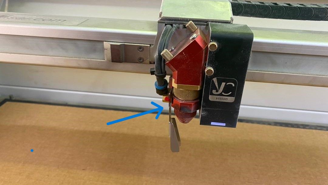
    Characterizing Laser Cutter


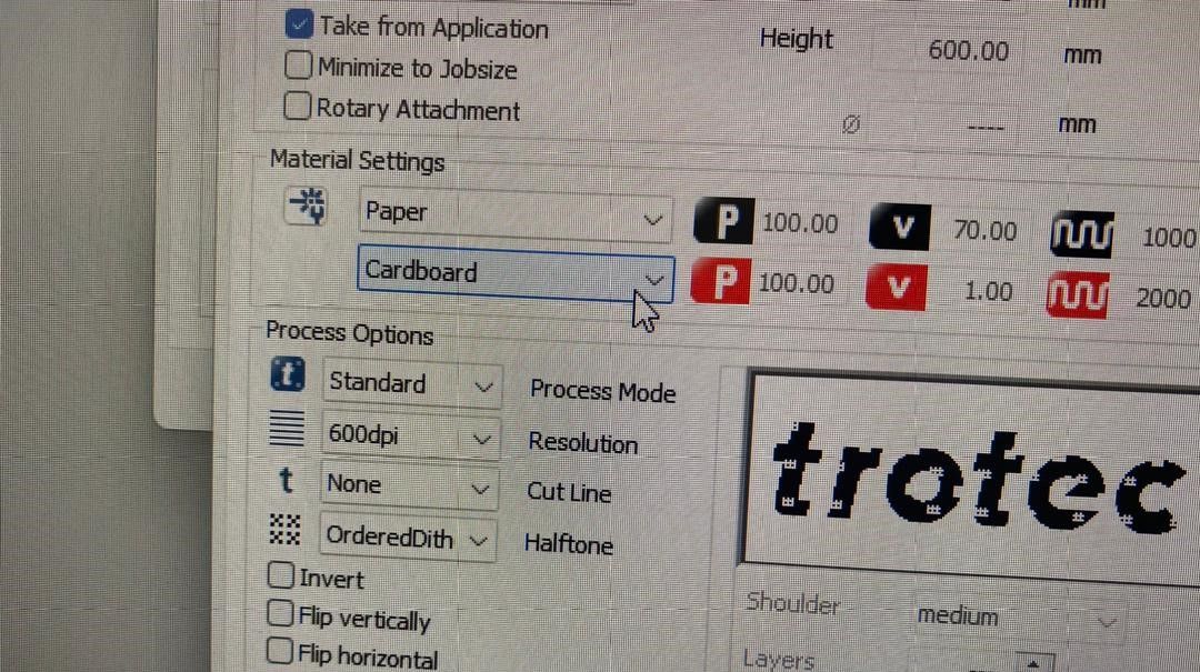
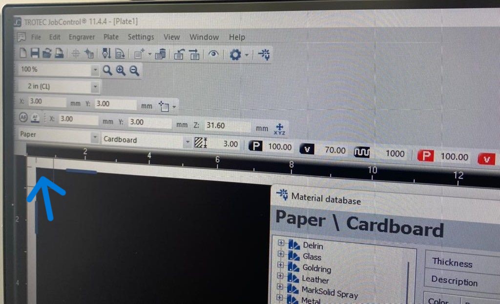
    We were asked to characterize laser-cutters focus, power, speed, rate, kerf, joint clearance. The Trotec has feature wherein you can color code various colors to have certain parameters linked to it. To have better understanding of these function, in the JobCenter go to settings -> Material template settings. Here you can see all the colors and you assign different functions and parameters to each of the colors.


                                                    Data play


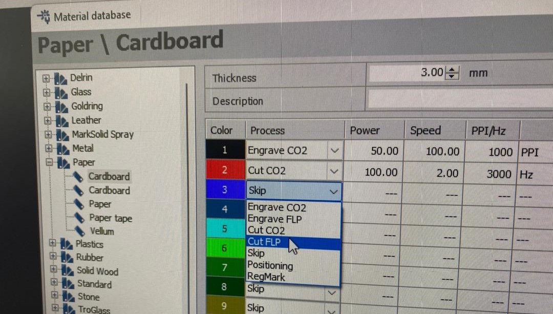
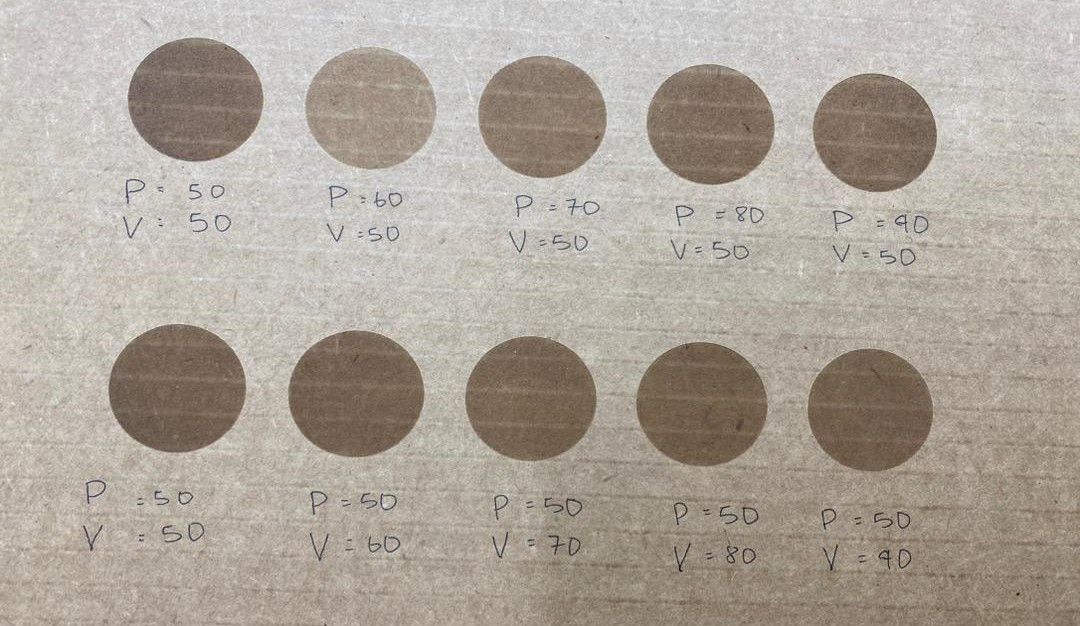
    To characterize the laser, the colors were are coded to have different powers and velocities in order keeping constant frequency which was 1000 to conduct a comparison study which could be ultimately used for references in the future.


                                                    Color coding


    We have seen the differences on engraving with different parameters like power and velocity as image shown below:


                                                    Laser character


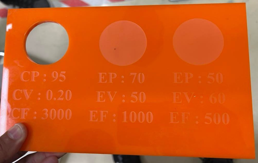
    Tested on acrylic for more practice:


                                                      Acrylic material


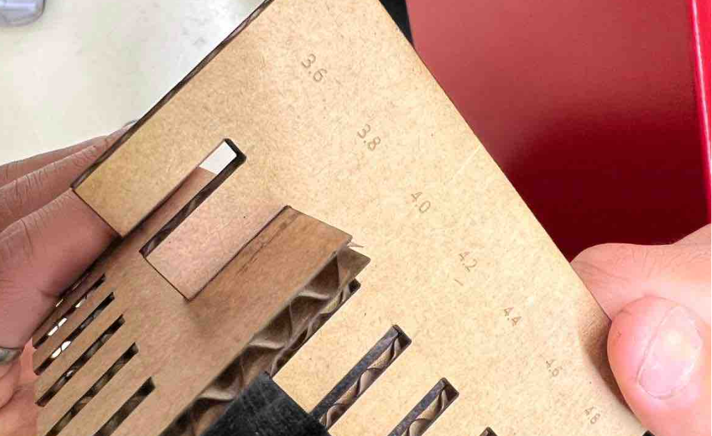
    Kerf and Joint Clearances


                                                      Product


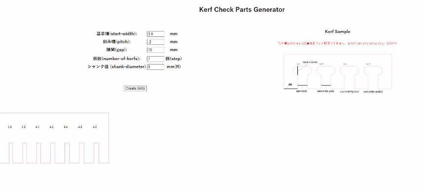
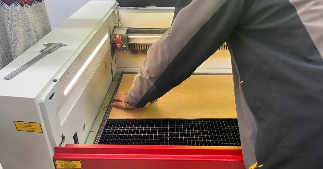
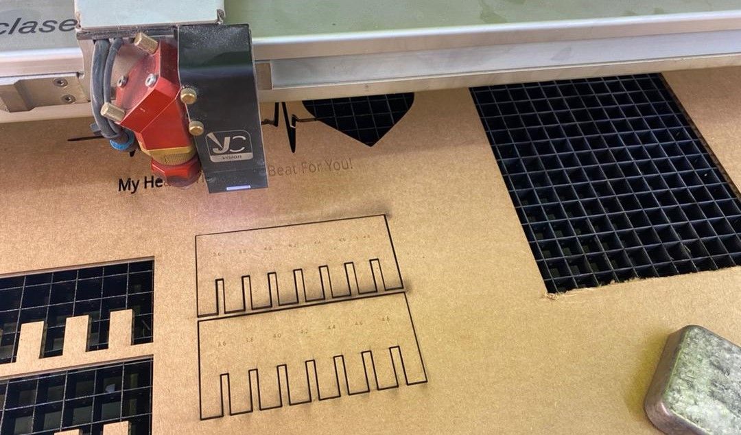
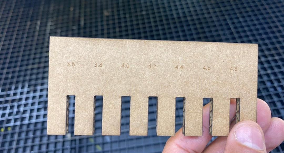
    The kerf check tool maker was Atsufumi Suzuki, FA2022 and to study kerf and joint clearances of the machine, we cut two combs from same material (cardboard). First we , measured the thickness of cardboard and then we kept slot thickness relative to its thickness as shown below. Slot size varied in 0.2 mm. We found out that the 4mm thick cardboard fits well in 3.8mm thick slot when press fit.


                                                      Product


    After cutting the comb, we measured the slot thickness with vernier and then subtracted it by our value in design and then divided by 2 as instructed by local instructor Ms.Zina and it came 0.15mm. So this is the kerf value of the machine that we used.


    Product Product


    Parametric Construction kit


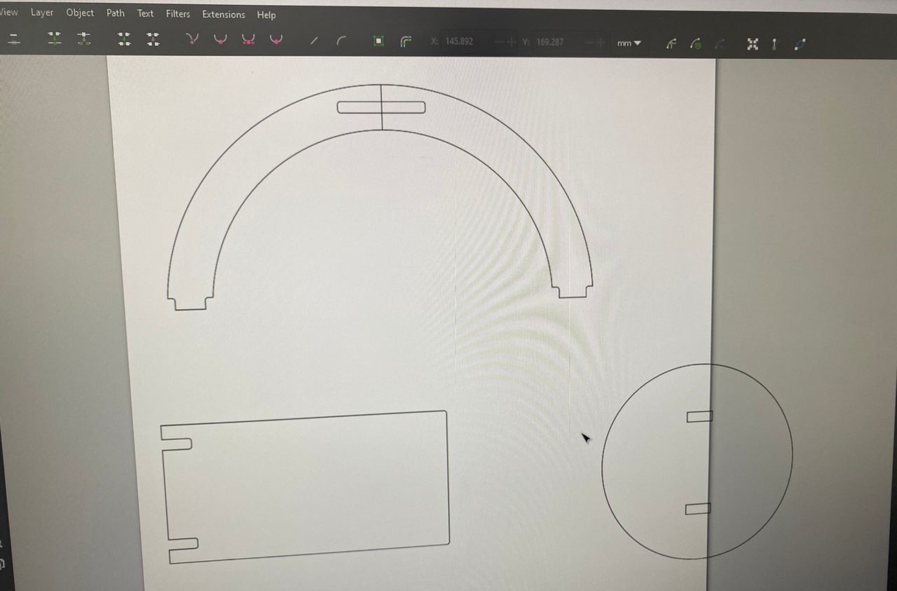
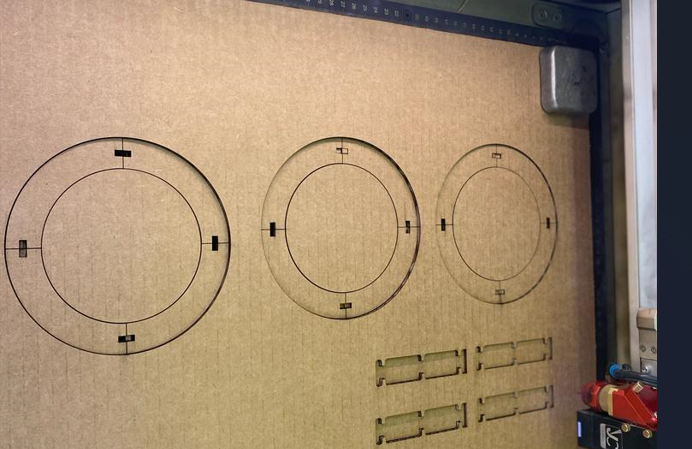
    For this, we were told to design parametric kit and cut. Therefore, I used Fusion360 to design parametric kit and then used laser cutter in JNWSFL to cut the kit from cardboard. It was also mentioned that we could use the kit for developing into many different shapes not just one.


                                                      Parametric design


    After designing, sketch saved as .dxf file in the folder. Then used Inkscape to fit the design in work piece and cut in the laser. I have designed mini-helipad model as simple press fit construction kit.


    2D image Product Press fit


    With this, the assignment for third week was concluded and I have tried including more photos with details as recommended by Mr.Rico.


    Reconstruction of Press Fit Kit


    Parameters of my construction kit


                                                      Parameters of Construction Kit


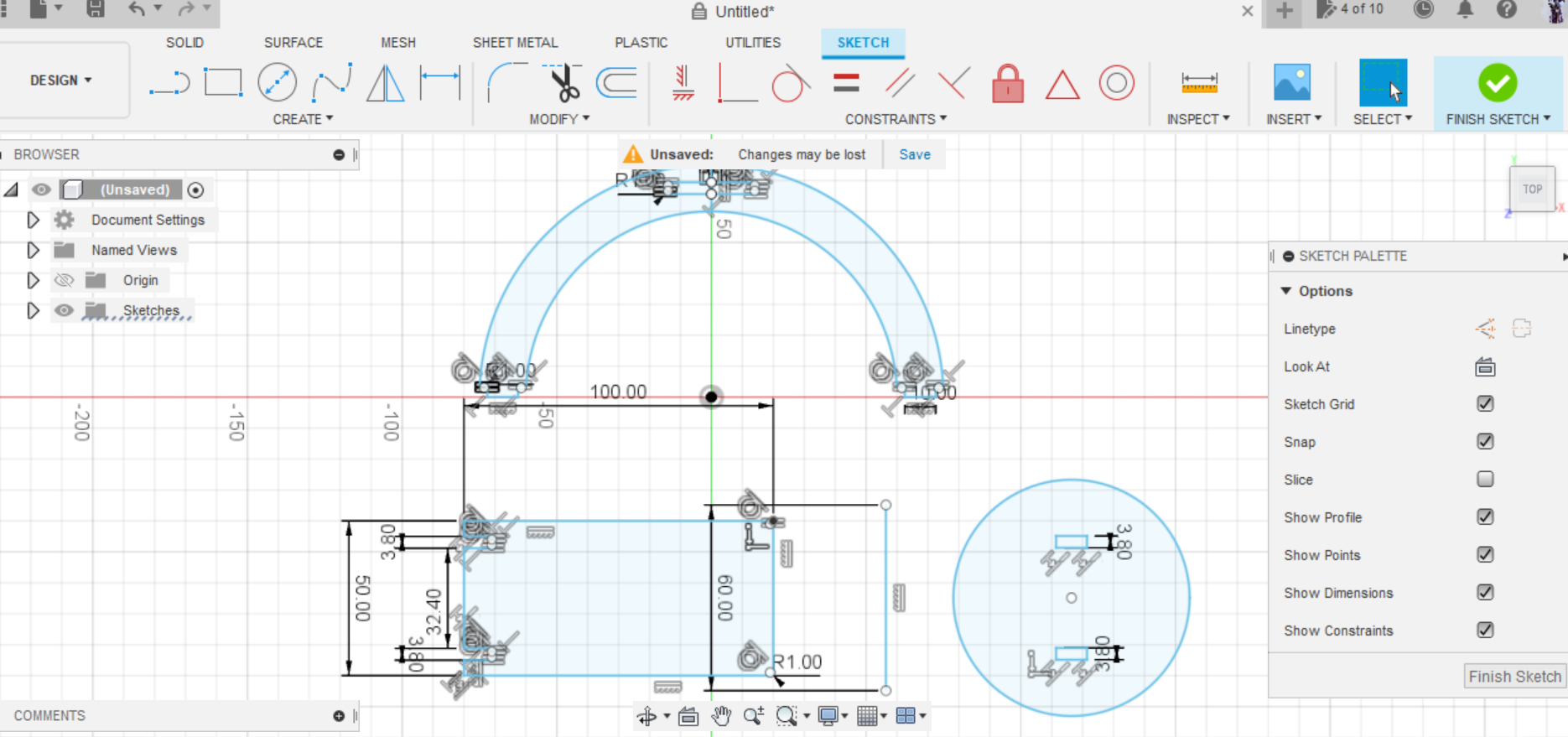
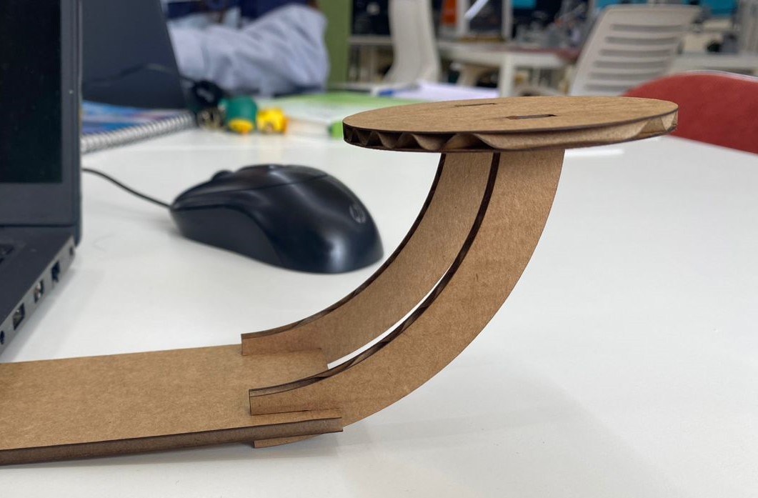
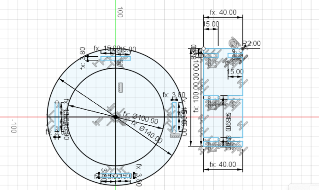
    As per recommendation from Professor Neil, Ms.Zina and Mr. Rico, I have re-designed parametric press fit construction as indicated by image below. In order to exactly press fit, I considered the kerf factor of 0.15mm and therefore made the slot width of 3.8mm (in post and frame of radial shoe rack model on 4mm thick cardboard).


    Press fit Press fit


    This design will have three layers of rack with four posts/column.
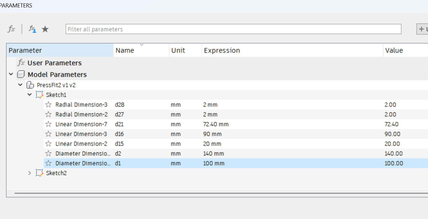
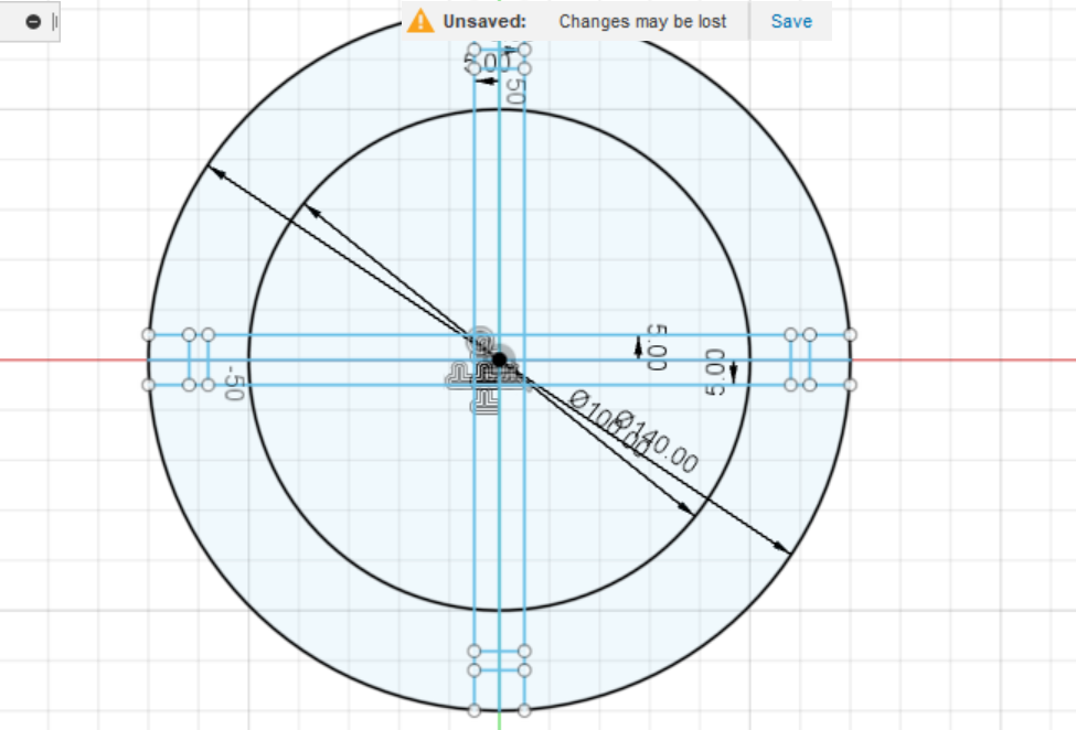
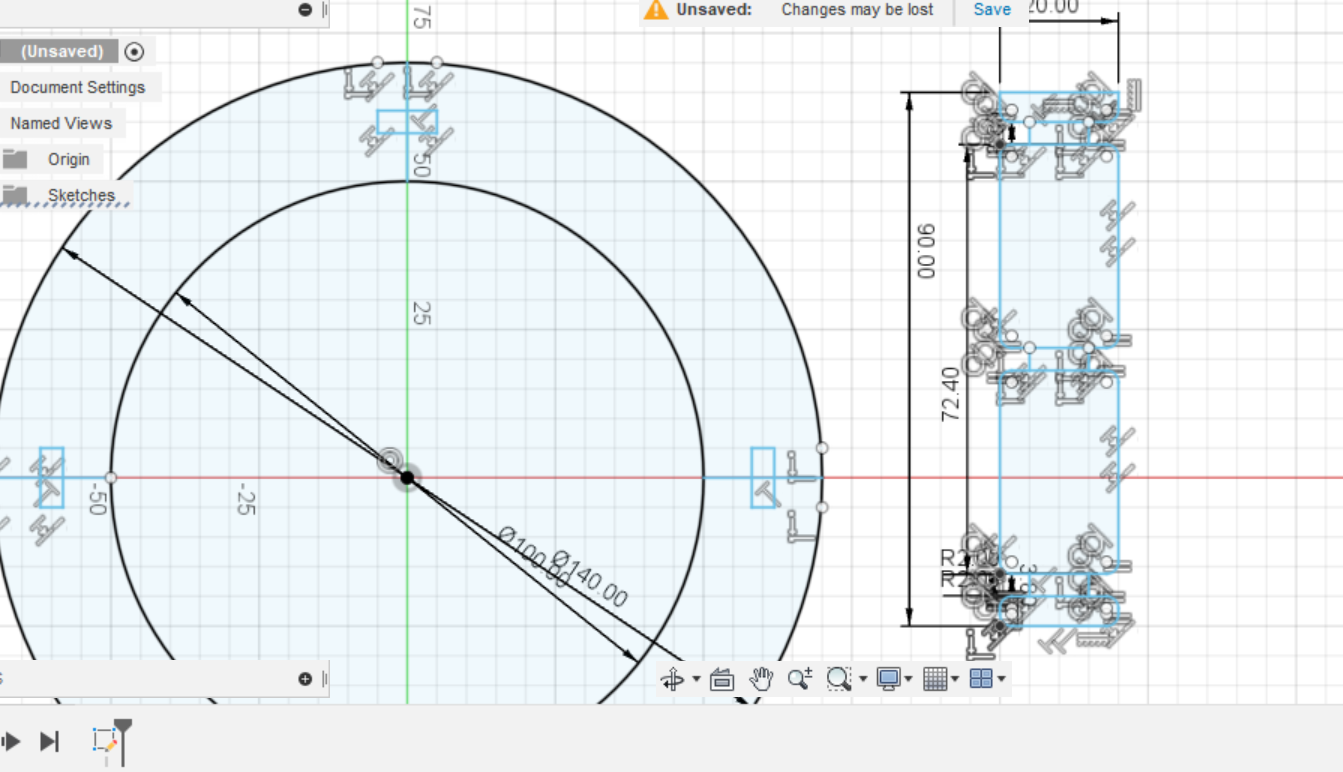
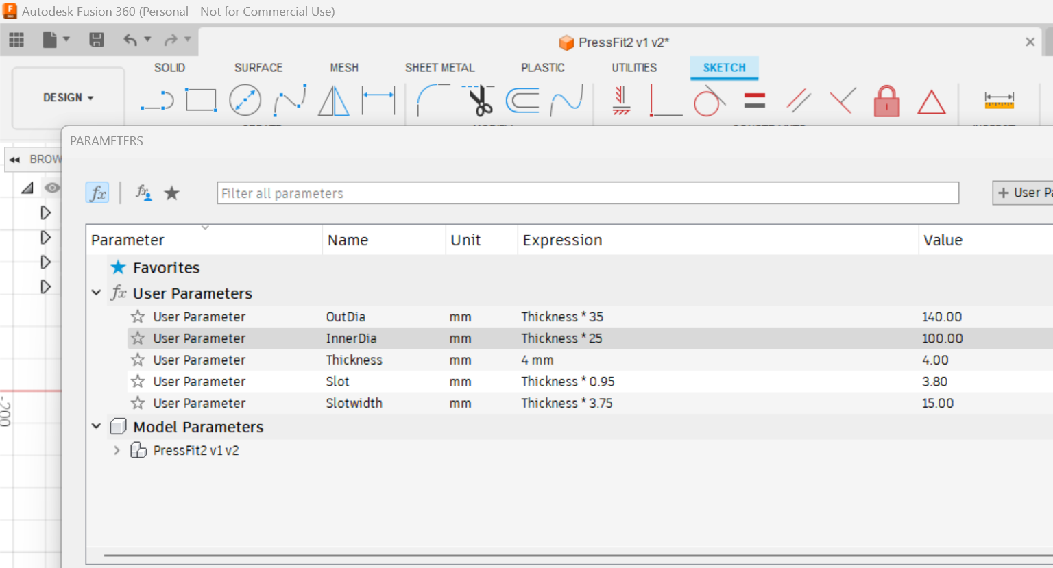


    User Parameters


    As recommended by Ms.JUNK, I have set the user parameters for my construction press fit kit. The main goal of setting this user parameter is to edit the designs easily when changing the thickness of the job piece and considering kerf. Here thickness of the job piece is used as reference and in case if you change the thickness, all other parameters get changed automatically without having to redesign the whole thing. The image below is the user parameters set for my press fit kit and sketch of it.


    User Parameters 2D Sketch


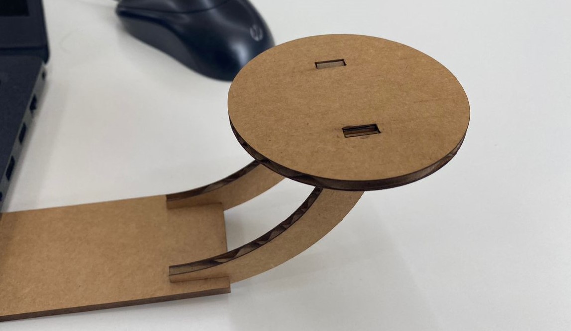
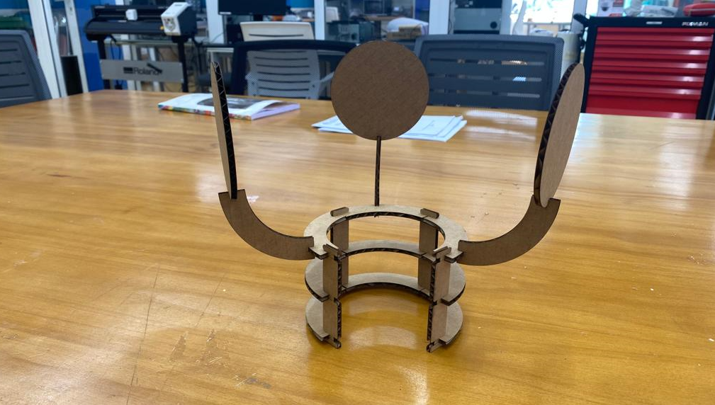
    Multiple Assemblies and cutting examples and shown below:


    After cutting the design in laser cutter I got the following components, and then I arranged as desired. Also tried to assemble in different ways to check if it fits well or to see if the components fall off.


    After cutting image Assembled shoe rack model Rolling test Offering table


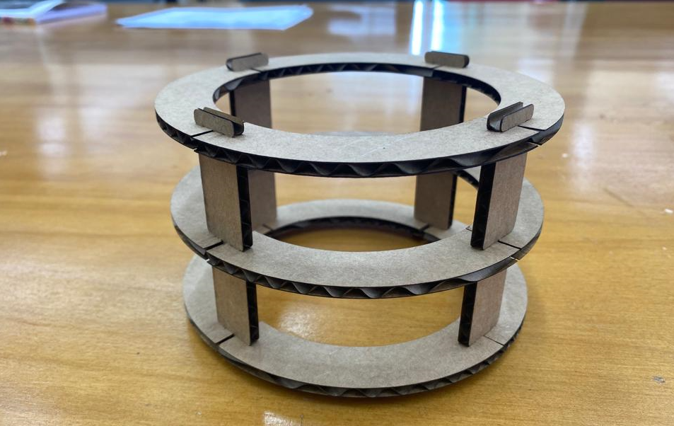
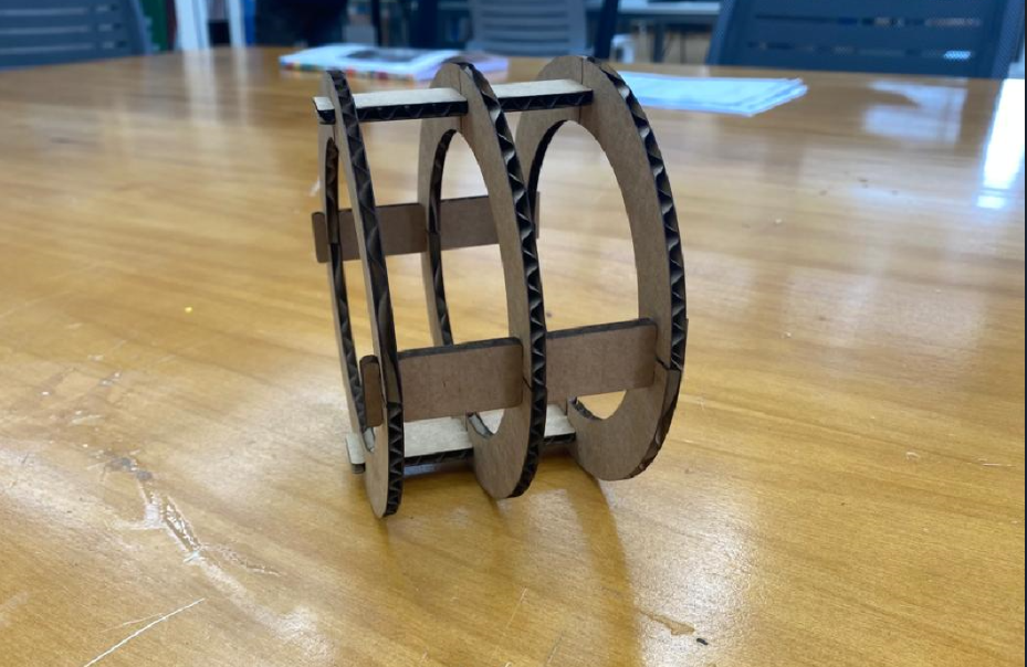
    With the slot of 3.8mm for 4mm thick cardboard the model found to be rigid and strong considering the kerf factor.


    Power, Speed and Frequency that I used


    I have tested for different power, speed and frequency to cut a cardboard. However, for my project I used power of 100, speed 80 and frequency of 1000. Using these parameter settings it cut satisfactorily for me. Reducing power couldn't cut as expected.


    Design File
    Designs File Week 3 User Parameters Sketch