Serial COmmunication protocol is a way of transmitting data in a line, one digital data after another.
For example if we want to send the 198 which in binary which are just ones and zeros will be 11000110.
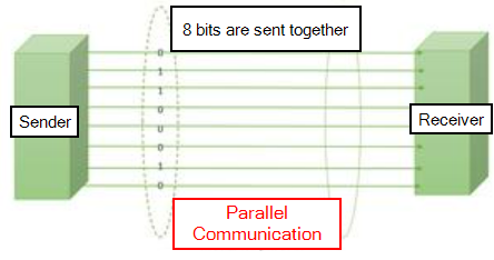
So in parallel communication, we connect one wire for each bit and send a high digital poles for ones, low value for zeros and do that at the same time.
This means that at one moment we can send all the bits at the same time but the disadvantage is that for this type of communication, you will need to use 8 connections plus a ground reference so in total it will need 9 cables for sending 8 bits of data. Similarly, if we want to send 16 bits of data, then we will need 17 cables to do the communication which will be very hectic and confusing too.
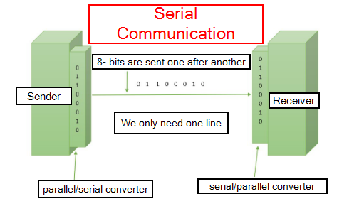
So instead in Serial Communication we will place the bits in series and then we send each one after another using just one cable.
The disadvantage of this type of communication is if we send 19 bits in parallel, we need only one clock pulse but if we send the same data using Serial communication, we will need 16 clock pulses which will make the communication 16 times slower.
Depending on the clock pulses, the serial communication can be Synchronous or Asynchronous. Synchronous uses the clock to send data at specific speed and time where as Asynchronous doesn't have a clock.
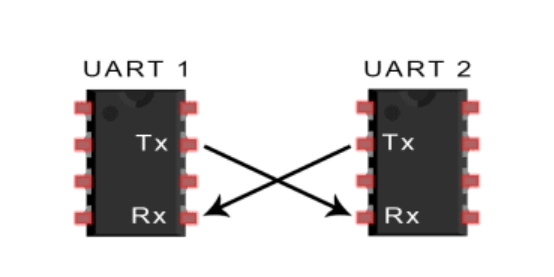
In UART communication, two UARTs communicate directly with each other. The transmitting UART converts parallel data from a controlling device like a CPU into serial form, transmits it in serial to the receiving UART, which then converts the serial data back into parallel data for the receiving device.
UARTs transmit data asynchronously, which means there is no clock signal to synchronize the output of bits from the transmitting UART to the sampling of bits by the receiving UART.
Without a clock, the receiving and transmitting UART need to be on the same baud rate, or bit rate. This allows the system to know where and when the bits have been clocked. Additionally, the transmitting UART adds a start and stop bit to the data being transmitted.
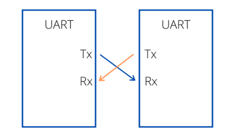
UART uses a two-wire system where the Rx and Tx pins are used to transfer and receive data.
A controlling device, such as a microcontroller, sends parallel data to the transmitting UART via a data bus.
The transmitting UART then transmits the data into serial data using a shift register and sends it to the receiving device using the Tx pin.
The receiving UART uses the Rx pin to receive the data and then converts the serial data back into parallel data using its shift register,
which is then sent back on the bus to the receiving end.
UART is being used often in microcontroller-based devices including GPS receivers or Bluetooth modules.
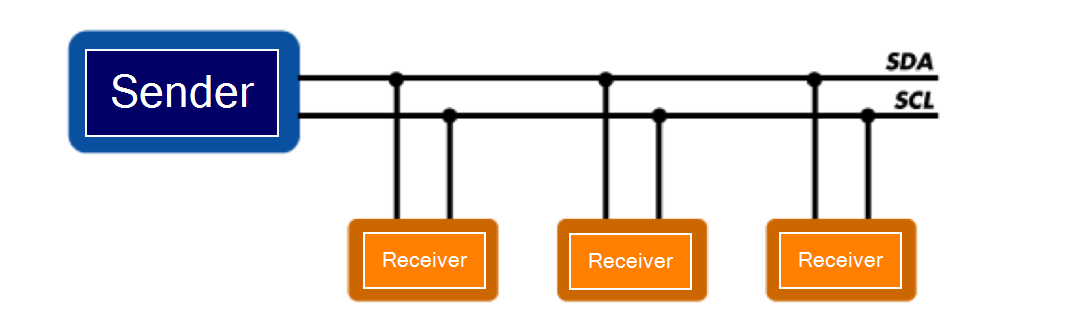
I2C, or Inter-Integrated Circuit, is a communication protocol often used in embedded systems as a way to transfer data between a sender (or multiple senders) and a single receiver (or multiple receiver) device.
It is a bidirectional two-wire serial bus that uses serial clock (SCL) and serial data (SDA) wires to send and manage data between devices connected to the bus.
Because I2C operates using a serial clock, it considered to be synchronous, which allows the output of bits to be synchronized to the
sampling of bits by a clock signal shared between the sender and the receiver.
A microcontroller is often used as the sender/transmitter device, and other peripheral devices are used as receiver devices.
Because all communication takes place on only two wires, all devices must have a unique address to identify it on the bus.
By using the unique address, the sender device is able to signal its read/write command to exchange communication between the two
over the bus.
Learnt more about the networking and communication especially about the types of serial communication. How it can be used and how it was used before. While going through documentations and videos, got to learn about the logic behind the connections. Also spent most of my time in programming.
It's amazing seeing how a single command can make so much difference. Overall it was a fun experience knowing about communications between boards and how it can be used to reduce causing so many errors. We can simply connect boards and reduce debugging.
Individual Assignment
For this weeks assignment we are suppose to design, build, and connect wired or wireless node(s) with network or bus addresses. So I decided to use my input/output board which i designed during the output week.
Since I've already tired Wired communication during my group assignment, I decided to go on with Wireless Communication.
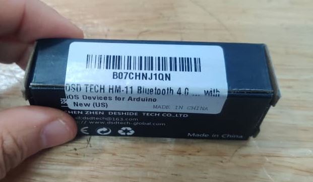
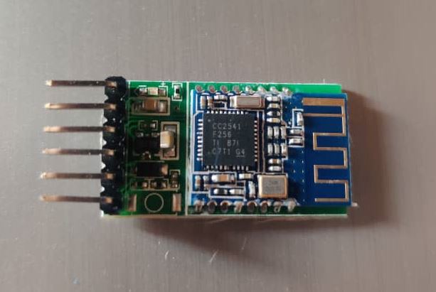
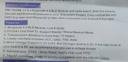
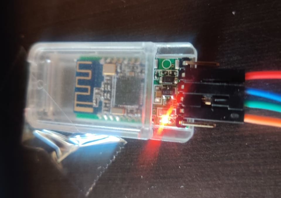
I found a Bluetooth module in our local lab and decided to try using that to communicate with my board. The bluetooth module is the DSD Tech HM-11 Bluetooth 4.0.
Bluetooth Module
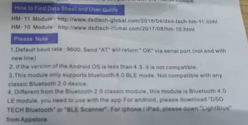
Here is the user module that was with the module.
And here is the link to the DATASHEET of the bluetooth module.
This bluetooth module uses BLE(Bluetooth Low Energy) protocol which is very much convenient for transferring small amounts of data between nearby devices and it also consumes low power compared to Bluetooth. So devices using this protocol runs for years by using small battery.
Also since it consumes less power, it can be used on mobile systems.
Since I was going to use a wireless communication for the first time, I went through a lot of tutorials and documentations that used bluetooth or anything related to that.
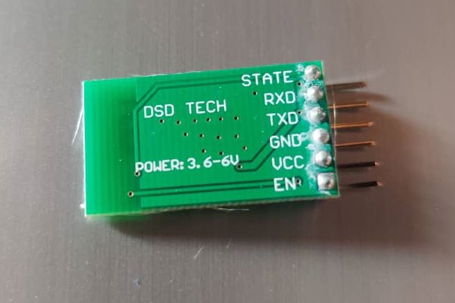
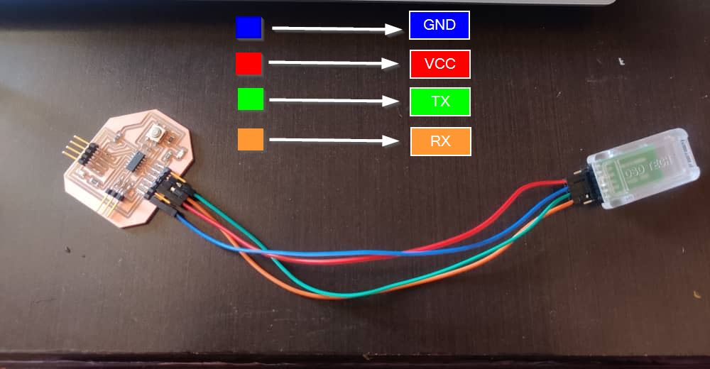
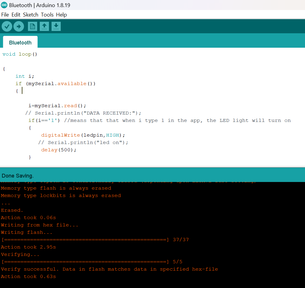
This is the code I used which I got from HERE.I made the changes for the RX and TX pin which for my board I used 8 and 9 pins of ATTINY1614 and LED that was soldered to my board was connected to the PIN 3 of ATTINY1614.
  #include <SoftwareSerial.h>
  SoftwareSerial mySerial(8,9);
  int ledpin=3;
  void setup()

  {
      mySerial.begin(9600);
      //Serial.begin(9600);
      pinMode(ledpin,OUTPUT);
  }

  void loop()

  {
      int i;
      if (mySerial.available())
      {

          i=mySerial.read();
         // Serial.println("DATA RECEIVED:");
          if(i=='2') //means that that when i type 1 in the app, the LED light will turn on
          {
              digitalWrite(ledpin,HIGH);
             // Serial.println("led on");
              delay(500);
          }

          if(i=='3') // similarly when i type 0 then the LED will turn off
          {
              digitalWrite(ledpin,LOW);
             // Serial.println("led off");
              delay(500);
          }
     }

  }
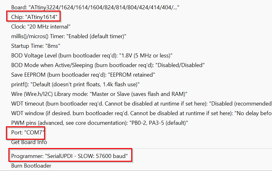
Then I complied and uploaded the code. Used ATTINY 1614 board and Programmer as "SerialUPDI-SLOW-57600 baud".
To Connect Bluetooth
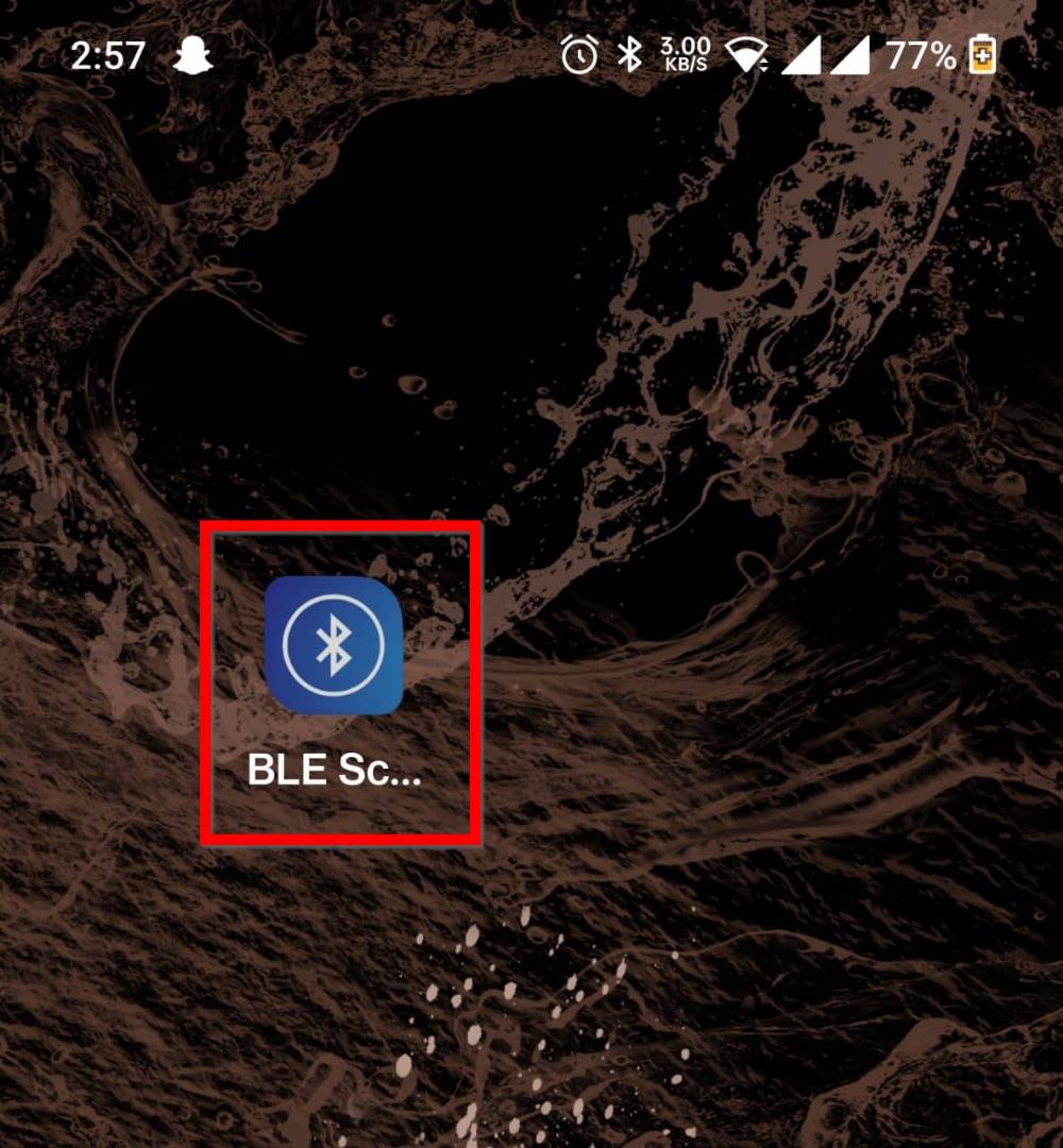
Now to connect to the bluetooth, I downloaded a BLE app for my android phone. I downloaded BLE Scanner.
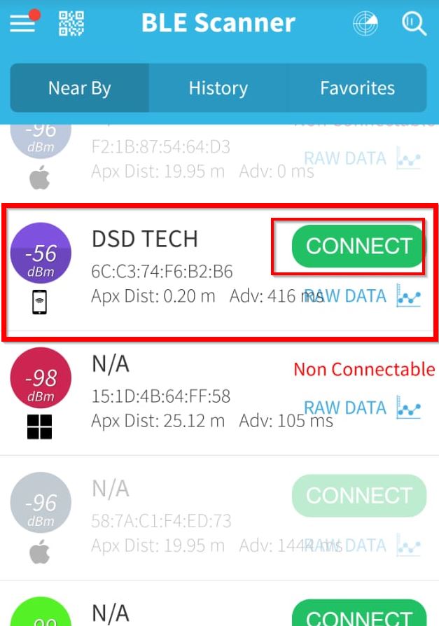
After installing the app, Open the app and this is what appears in the screen. It will show all the devices available to connect.
The app is showing the bluetooth module by its name. So connect to that.
Before we connect to the Bluetooth, the red LED on the module will simply "Blink".
After the Bluetooth gets connected, the the bluetooth module will stop BLINKING.
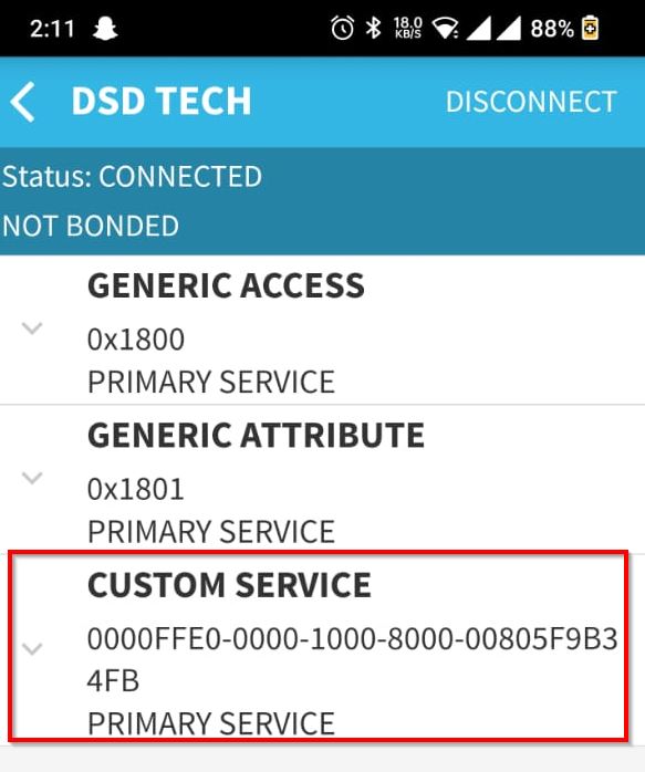
CLick on the "CUSTOM SERVICE" to write our command.
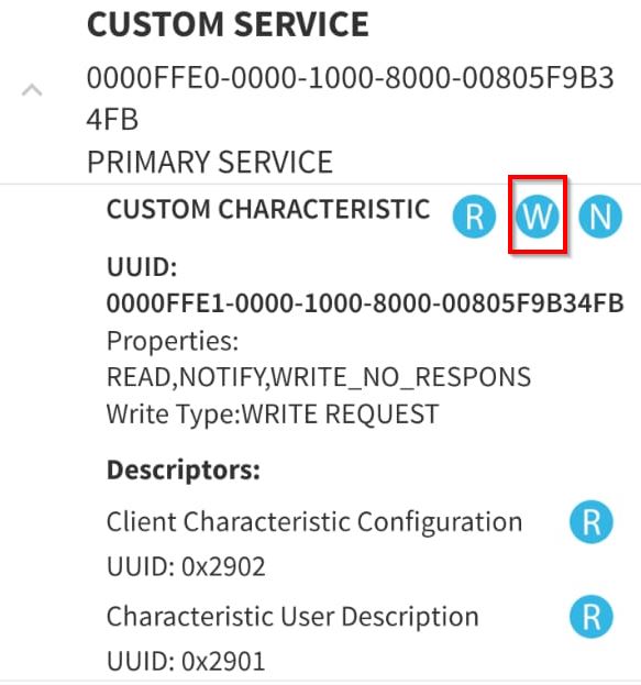
Then click on the Write Value and select TEXT. Now simply type 2 of turning ON the LED and 3 for turning OFF the LED.
Working Video
Reflection
It was a fun week again. I was able to learn about communicating boards using wired and wireless communication. Learnt a lot about the connections since I made enough mistakes doing the group assignment. I was able to figure out how to light LED using Bluetooth module which was high level for me. Definitely came out wiser again this week.
Main things to keep in mind that all the pins in the Arduino or any other board will not be applicable as RX where TX wont be a problem.