Input Devices
Task for Week 11
- - Group Assignment
- - probe an input device's analog levels and digital signals
- - Individual Assignment
- - measure something: add a sensor to a microcontroller board that you have designed and read it
Group Assignment
- Link to the group Assignment
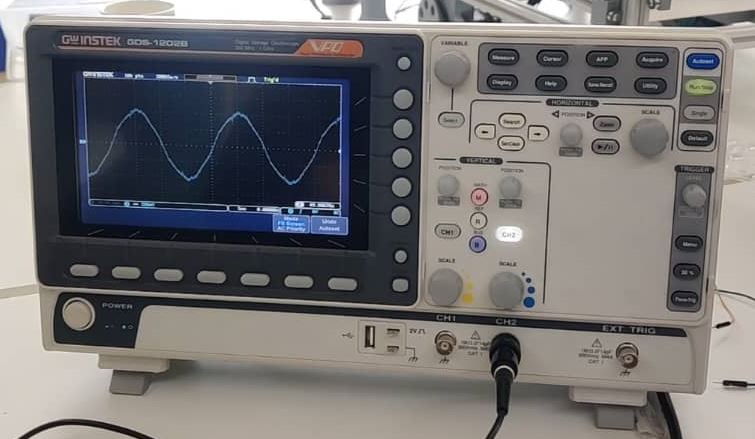
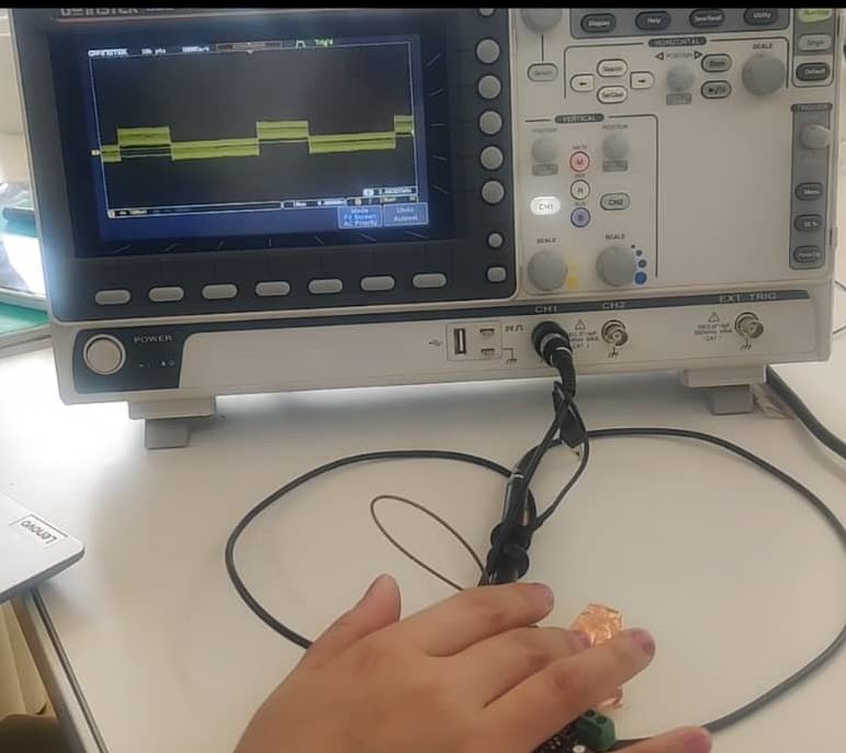
- This week we were asked to probe an input device's analog levels and digital signals. To do so we used an oscilloscope.
- As an input device we used PIR sensor and Capacitive Touch sensor.
- Connected the PIR with Arduino Uno board and also connected the Touch sensor to the digital pin of Arduino.
- We were able to see the changes in the signals as the sensors were able to detect changes in the Distance in terms of PIR and touch in terms of Capacitive touch sensor.
- I was basically the one trying to get the signals on the display screen of the oscilloscope.
Individual Assignment
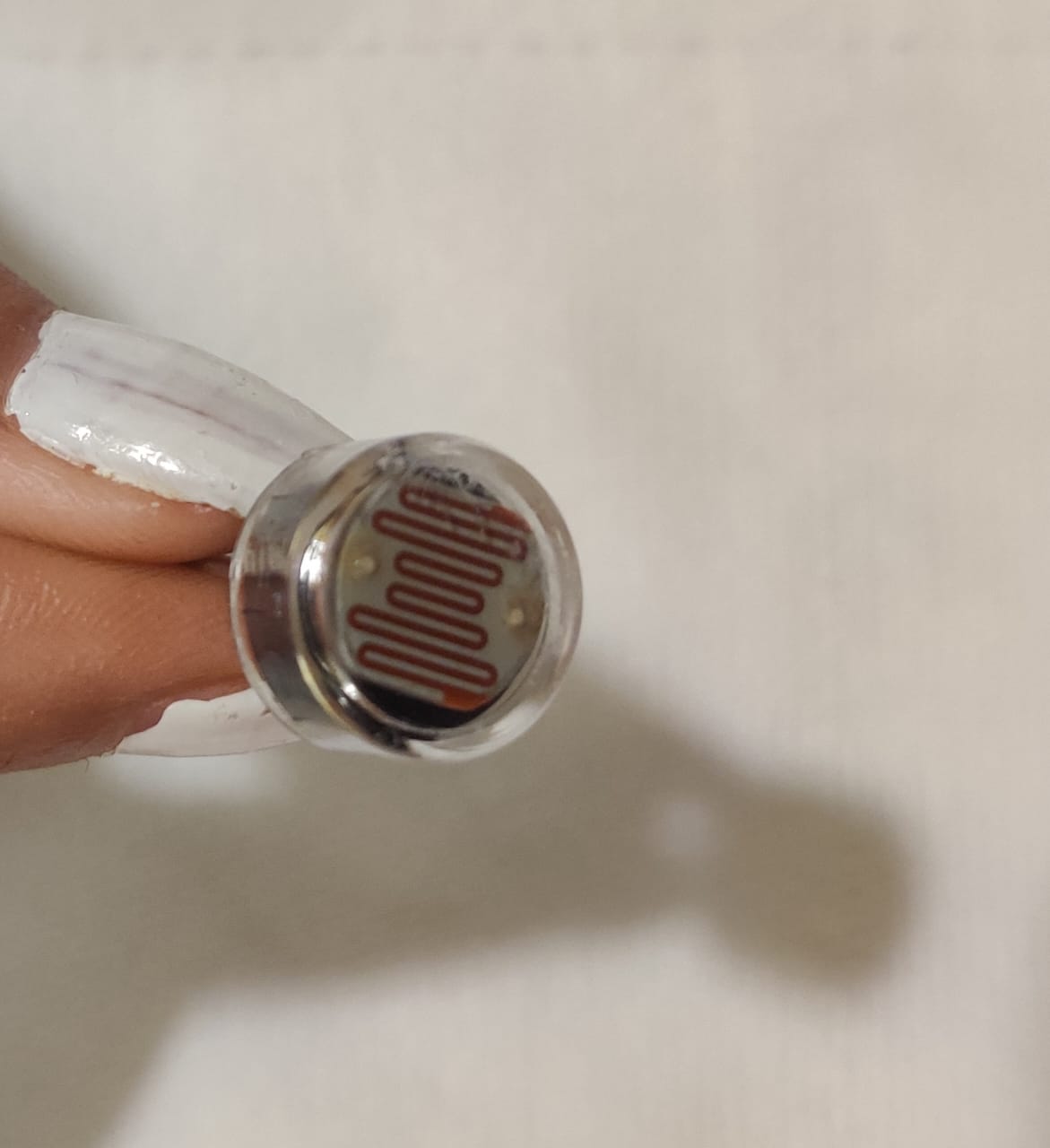
For this weeks assignment I decided to use PIR sensor and LDR sensor which I'll be using for my final project. The PIR(Passive Infrared) sensor measures infrared light radiating from objects in its field of view, often used to detect motions. They are commonly used in security alarms and automatic lighting applications. LDR(Light Dependent Resistor) sensor also known as Photo resistor. It is a type of resistor whose resistance changes depending on the amount of light falling on its surface. To know more about these sensors, please go through these websites.
With LDR Sensor
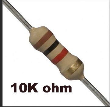
- Since we weren't allowed to use breadboard for this week, had to solder the PIR sensor to the resistor of 10K ohms and jumper wires so that it can directly connect with my board.
- I'll be using the output device board that I designed using ATTINY1614 as the microcontroller. I used 4 header pins so it was more than enough since PIR sensor needed only one signal pin.
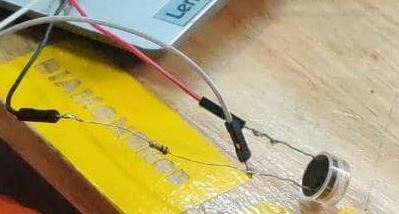
- Connected the Ground of my Board to one pin of the LDR sensor. The other end of the LDR sensor was soldered to 10K ohms resistor and the other end of the resistor connect to the VCC of my Board. For the signal pin, I soldered one jumper wire to the other end of the resistor which was connected to the end of LDR. Hence the circuit was completed
- Wanted the LDR to detect the brightness in the room and when it was dark, wanted it to light the LED in my board and vice versa.
- Code I used is as follows and got the code from Here
- Here a video of how it worked.
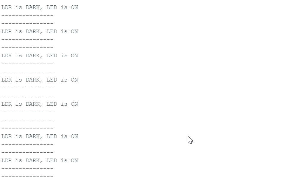
- Serial Monitor
      const int ledPin = 3;

      const int ldrPin = 2;

      void setup() {

      Serial.begin(9600);

      pinMode(ledPin, OUTPUT);

      pinMode(ldrPin, INPUT);

      }

      void loop() {

      int ldrStatus = analogRead(ldrPin);

      if (ldrStatus <=300) {

      digitalWrite(ledPin, HIGH);

      Serial.println("LDR is DARK, LED is ON");

      }

      else {

      digitalWrite(ledPin, LOW);

      Serial.println("---------------");

      }

      }
With PIR sensor
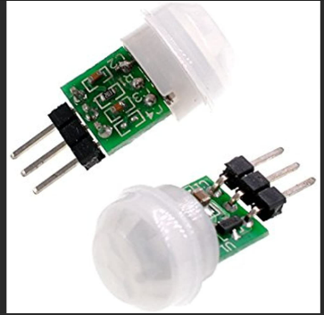
- PIR sensor was easily available in our Lab and it will be the main sensor used in my final project.
- Connected the PIR GND and VCC to my Board GND and VCC and Connected the signal pin to my board Attiny1614 digital pin 2.
- The LED on my board was connected to the Digital pin number 3 of ATTINY1614.
- The LED was suppose to Light up when the PIR sensor senses movement.
- Shown below is the code I used which I got it from here
- Here is a short video of how it worked.
  int LED = 3;
  int PIR = 2;

  void setup() {

  // initialize digital pin 3 as an output for LED

  pinMode(LED, OUTPUT);

  //initialize digital pin 2 as input for PIR

  pinMode(PIR, INPUT);

  //initialization time for PIR sensor to warm up

  //blink LED to show that something is happening

  for(int i = 0; i < 10; i++) {

  digitalWrite(LED, LOW);

  delay(3000);

  digitalWrite(LED, HIGH);

  delay(3000);

  }

  }

  void loop() {

  //read PIR sensor, if High light LED for 5 seconds

  //if low, check again

  if(digitalRead(PIR) == HIGH) {

  digitalWrite(LED, HIGH);

  delay(5000);

  } else {

  digitalWrite(LED, LOW);

  }

  }