15. Interface and application programming
This week's task is to create an interface. I had never done anything like this before, so I looked for information about different options.
I would have liked to create an interface for my final project, but given the knowledge base I started from, I finally made something simpler, using all possible options by connecting a board made during the Academy and a device.
My first thought was to use p5.js and create an on-line interface to control the boards, but after some research, I realised that it is complicated to control the serial ports through the Internet, so I decided to start with Processing as it is the program that they said it was simpler.
The board
The interface is intended for my final project, so I used the board designed for the project (the slave).
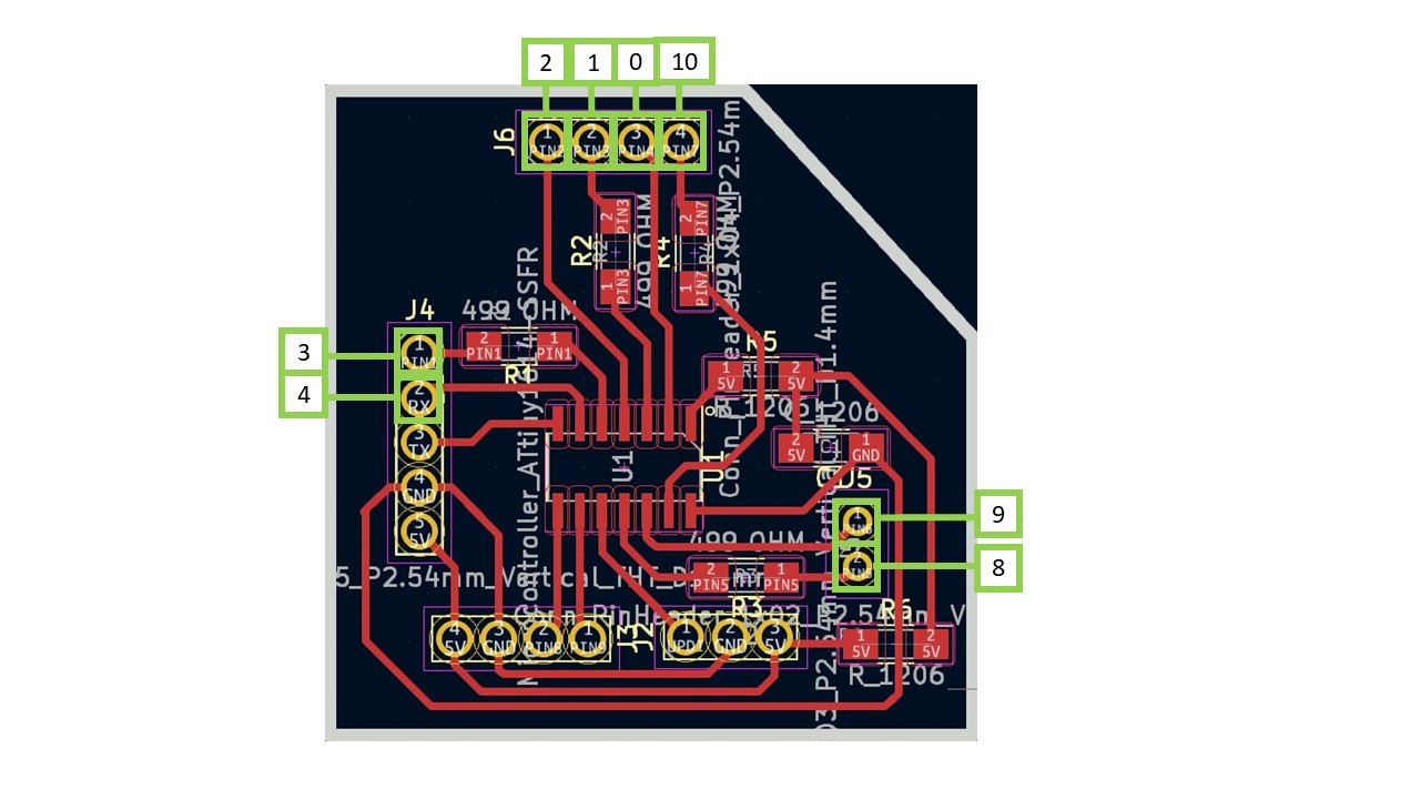
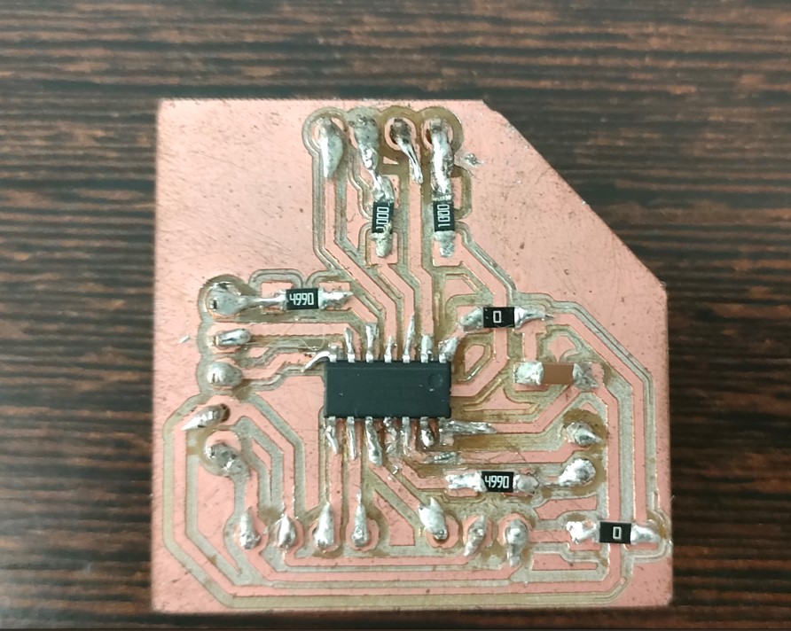
This board has an ATtiny 1614 microcontroller and a lot of free pins as shown in the picture.
The only bad thing about this microcontroller is that it cannot communicate directly with the computer and you have to use a bridge. In this case, as you can see in the video, the barduino board was used as a bridge, giving power to the pins needed for UPDI programming. How to proceed is done in the same way as explained in the Networking and communications week, where are also the files to replicate it.
This means that I used the Barduino board as a UART to USB converter, similar to an FTDI cable. The Barduino board has an embedded microcontroller (SAMD11C14) that supports UART (Universal Asynchronous Receiver-Transmitter) communication through its RX (receiver) and TX (transmitter) pins.
Processing
This is my first time using Processing, so I had to follow some tutorials to learn how to use it. They are easy to find. The best thing is that it's like the Arduino IDE, with a configuration void and a drawing void that acts as the main loop. So learning to program it is similar to Arduino (although I'm not particularly good at programming...). Also, Processing has a good community and website to help you learn.
The first thing I did was to create the visual content of the interface, and then program what it has to do. So, I tried to draw some triangles and since it's a simple function, I chose to do it directly in the interface instead of drawing it and importing it in SVG.
First I globally defined all the objects and in the configuration loop I set them up. It is important to do this in the configuration loop and not in the drawing loop to have a faster program as you will define it only once.
The idea of the interface created is a simplification of my project. I have only 4 triangles (instead of 40), and every time I put a triangle, the interface will show me which one is on.
What does the code do?
The intention of the final project is a 4 in a row. This is that I will be connecting pieces (triangles) from two teams (each team of a colour) and my board must know the position of the piece and the colour.
I have made a first approximation. This is that I'm not going to do the 4 in stripe, because with only one board I only have enough pins for 4 triangles (8 analogue pins). Instead, I am only going to get the position of the triangle and the colour of the placed triangle. The interface will only detect if a triangle is placed and the equivalent will light up on the screen, although it can be improved to adapt it to the final project.
The slave code will therefore have 4 triangles. Each pair of pins activates a triangle. Thus, pins 1 and 2 activate triangle 0; pins 3 and 4 activate triangle 1; pins 8 and 9 activate triangle 2; and pins 0 and 10 activate triangle 4.
For each pair of pins (each triangle) I activate the first pin (HIGH) and check for current. If there is, the part of team 1 (red) is in place. If not, I activate the second pin and deactivate the first one. If there is current, the team 2 part (yellow) is in place.
Team 1 therefore collects a 1 and team 2 a 2.
On the other hand, the interface does nothing more than count if in each position of the triangles, any value is different from 0. If the counter of each triangle is greater than 0, it turns on.
So, I have connected my slave board (files in the development of my final project) to a barduino through Tx and I have programmed it to send a message by serial that the triangle is turned on. This programming will be needed later in the final project.
The code uploaded to my board:
        int triangulos[] = {0, 0, 0, 0}; //  4 possible triangles in different locations
        int pin1Triangulos[] = {1, 3, 8, 0}; // Pin 1 (first pin of the pin pair that will activate each triangle)
        int pin2Triangulos[] = {2, 4, 9, 10}; // Pin 2 (second pin of the pin pair that will activate each triangle)

        unsigned long previousMillis = 0;  // will store last time LED was updated
        const long interval = 500;  // interval at which to blink (milliseconds)

        bool check(int pin1, int pin2) {
          pinMode(pin1, INPUT_PULLUP);
          pinMode(pin2, OUTPUT);
          digitalWrite(pin2, LOW);
          if (digitalRead(pin1) == 0) {
            return true;
          }
          else {
            return false;
          }
        }

        void ledOn(int pin1, int pin2) {
          pinMode(pin1, OUTPUT);
          pinMode(pin2, OUTPUT);
          digitalWrite(pin1, HIGH);
          digitalWrite(pin2, LOW);
        }

        void setup() {
          // put your setup code here, to run once:
          Serial.begin(9600);
        }

        void loop() {
          for (int i = 0; i < 4; i++) {
            if (triangulos[i] == 0) {
              if (check(pin1Triangulos[i], pin2Triangulos[i])) { //Check if there is current from pin1 to pin2 (if LED is in one direction = team 1).
                triangulos[i] = 1;
                Serial.print("Connected pos  ");
                Serial.println(1);
                ledOn(pin1Triangulos[i], pin2Triangulos[i]);
              }
              else if (check(pin2Triangulos[i], pin1Triangulos[i])) { //Check if there is current from pin2 to pin1 (if LED is in one direction = team 2).
                triangulos[i] = 2;
                Serial.print("Connected pos  ");
                Serial.println(2);
                ledOn(pin2Triangulos[i], pin1Triangulos[i]);
              }
            }

            else {
              unsigned long currentMillis = millis();
              if (currentMillis - previousMillis >= interval) {
                // save the last time you blinked the LED
                previousMillis = currentMillis;

                if (triangulos[i] == 1) {
                  Serial.print("triangulo  ");
                  Serial.println(i);
                  Serial.println("Cheking 1");
                  if (!check(pin1Triangulos[i], pin2Triangulos[i])) {
                    triangulos[i] = 0;
                  }
                  else {
                    ledOn(pin1Triangulos[i], pin2Triangulos[i]); // lights up the LED (team 1)
                  }
                }
                else if (triangulos[i] == 2) {
                  Serial.print("triangulo  ");
                  Serial.println(i);
                  Serial.println("Cheking 2");
                  if (!check(pin2Triangulos[i], pin1Triangulos[i])) {
                    triangulos[i] = 0;
                  }
                  else {
                    ledOn(pin2Triangulos[i], pin1Triangulos[i]); // lights up the LED (team 2)
                  }
                }
              }
            }
          }
        }
On the other hand, Processing reads that information sent by serial. I have proposed a counter so that if we read that a triangle stops being 0, in my interface its image is illuminated.
The Processing code:
        import processing.serial.*;
import processing.opengl.*;

Serial arduino; // Serial Object for communication with Arduino
int count0 = 0; // Counter for the number of times "triangle 0" is displayed
int count1 = 0; // Counter for the number of times "triangle 1" is displayed
int count2 = 0; // Counter for the number of times "triangle 2" is displayed
int count3 = 0; // Counter for the number of times "triangle 3" is displayed

void setup() {
  size(400, 400, OPENGL);

  // Configuring communication with the Arduino
  String portName = "COM7"; // Switch to the correct COM port (this is my COM port used)
  arduino = new Serial(this, portName, 9600);
  arduino.bufferUntil('\n'); // Wait until a line break is received
}

void draw() {
  background(255);

  // Drawing equilateral triangles
  noStroke();

  // Triangle 0 (if count0 is greater than 0, colour is changed to green)
  if (count0 > 0) {
    fill(0, 255, 0); // Green
  } else {
    fill(0); // Black
  }
  drawEquilateralTriangle(width * 0.25, height * 0.5, 100);

  // Triangle 1 (if count1 is greater than 0, colour is changed to green)
  if (count1 > 0) {
    fill(0, 255, 0); // Green
  } else {
    fill(0); // Black
  }
  drawEquilateralTriangle(width * 0.75, height * 0.5, 100);

  // Triangle 2 (if count2 is greater than 0, colour is changed to green)
  if (count2 > 0) {
    fill(0, 255, 0); // Green
  } else {
    fill(0); // Black
  }
  drawEquilateralTriangle(width * 0.5, height * 0.25, 100);

  // Triangle 3 (if count3 is greater than 0, colour is changed to green)
  if (count3 > 0) {
    fill(0, 255, 0); // Green
  } else {
    fill(0); // Black
  }
  drawEquilateralTriangle(width * 0.5, height * 0.75, 100);
}

void drawEquilateralTriangle(float x, float y, float size) {
  float h = size * sqrt(3) / 2; // Height of equilateral triangle
  beginShape();
  vertex(x, y - h / 2);
  vertex(x - size / 2, y + h / 2);
  vertex(x + size / 2, y + h / 2);
  endShape(CLOSE);
}

void serialEvent(Serial port) {
  String mensaje = port.readStringUntil('\n'); // Read the message received

  if (mensaje != null) {
    mensaje = trim(mensaje); // Removing blanks

    if (mensaje.contains("triangulo") && mensaje.contains("0")) {
      count0++; // Increasing the counter
      println("The number of times 'triangle 0' appears is: " + count0);
    }
    else if (mensaje.contains("triangulo") && mensaje.contains("1")) {
      count1++; // Increasing the counter
      println("The number of times 'triangle 1' appears is: " + count1);
    }
    else if (mensaje.contains("triangulo") && mensaje.contains("2")) {
      count2++; // Increasing the counter
      println("The number of times 'triangle 2' appears is: " + count2);
    }
    else if (mensaje.contains("triangulo") && mensaje.contains("3")) {
      count3++; // Increasing the counter
      println("The number of times 'triangle 3' appears is: " + count3);
    }
  }
}
This is how it looks like, and a video of it working:

Group assigment
The group assigment can be viewed at Group Assigment page.
Files
The Interface_program.
The Arduino_code.
Conclusions
The main conclusion of this week is that I had a hard time getting started and I would have liked to do something more complete. However, I have wasted more time than I would have liked researching possible ways of creating an interface and finally I have settled on the one that many people proposed as the simplest.
My recommendation is that anyone who doesn't know much about programming should work with Processing, as it's relatively easy to learn if you've never used Arduino before. You can also add figures or drawings, so you can make a more user-friendly interface.