14. Networking and communications
This week we have learned how to implement and interpret network protocols and/or communication protocols.
Different boards can communicate with each other using different protocols. A protocol allows information to be exchanged by means of a set of agreed rules.
A communication network is a set of interconnected electronic devices for the purpose of transmitting information and/or data between them. This network allows devices to communicate with each other, allowing users to share information and resources.
Communication networks are used in all areas of technology. There are several types of communication networks, such as LAN (Local Area Network) networks that connect devices in a close geographical area, WAN (Wide Area Network) networks that connect devices in larger geographical areas, and the Internet, which is a global network that interconnects networks around the world.
In general, a communication network operates by means of a transmission medium, such as fiber optics, coaxial cable, or radio waves, which allows the transmission of information from one device to another. These devices are connected to each other through physical cables or wireless connections. Communication between devices can be through different communication protocols, such as TCP/IP, Ethernet, Wi-Fi, Bluetooth, and others.
Wireless network
Wireless devices communicate with each other by sending and receiving radio signals via an antenna. The radio signals are emitted in a specific frequency band and on different channels to avoid interference.
There are several methods of wireless network communication, such as:
- Wifi.Wi-Fi communication is commonly used to connect devices to the Internet or a local network. This technology uses radio waves for data transmission.
- Bluetooth.This technology is used to establish short-range wireless connections between devices.
- Others. Such as ZigBee technology which is used to create networks of low speed wireless personal area devices, RFID (Radio Frequency Identification) technology which is used to identify and track objects using electronic identification tags, or NFC (Near Field Communication) technology which allows very short range communication (usually a few centimeters).
Wired network
Wired network communication is a network technology used to connect multiple devices through wires that transmit electrical signals. Unlike wireless communication, wired network communication uses physical wires to transmit data instead of radio waves, which allows for higher data transfer speed and capacity. There are several types of wired communication networks, including:
- Ethernet. A type of local area network (LAN) that uses cables to connect devices on a network. A device acts as the server and communicates with other devices on the network to share information. The devices are connected through an Ethernet router or switch.
- Fiber optics. A method of data transmission that uses fiber optic cables to transmit light signals between devices. This method has high data transfer speed and high data storage capacity and security.
- Coaxial cable. A type of cable used to connect network devices in LAN systems. It consists of a core cable surrounded by an insulating layer and a high-frequency sheath layer.
- Twisted pair. This is another form of network cabling used in LAN systems. This method uses two copper wires twisted together to create a pair and minimize electrical interference.
There are several ways to connect two wired microcontrollers to communicate, each depending on the communication protocol used and the specific application.
- Serial communication (UART). The two microcontrollers communicate via a serial communication protocol such as Universal Asynchronous Receiver-Transmitter (UART). Serial communication uses a single pair of wires (RX/TX) to transmit and receive data.
- Synchronous serial communication (SPI). It is a serial communication protocol used when a high data transfer rate is required. This communication uses three or four wires (MOSI, MISO, SCK and SS) to transmit and receive data.
- Bidirectional serial communication (I2C). It is a communication protocol commonly used in embedded systems to interconnect devices and microcontrollers. It uses a pair of wires (SDA and SCL) to transmit and receive data.
- Others
Tests
This week for me is very complicated. I start from 0 knowledge, so I have looked for information to start with the simplest.
I will need some of the above mentioned communication protocols for my project. Therefore, it was interesting to test them. One of the necessary tasks is to program an ATtiny 1614. This microcontroller is not able to communicate directly with the computer. Therefore, I programmed it via a SAMD11C14 with the UPDI.
To do so, it is only necessary to select the Rx and Tx pins of the SAMD, each with a resistance of 4.99 Kohm. Then these two resistors are connected at the output to the UPDI pin of the ATtiny. In the SAMD microprocessor used, the Rx and Tx pins are 1 and 14 respectively (5 and 4 in programming).
In practice, I used the Barduino (with the SAMD, i.e. the top pins) to program an ATtiny. However, there is a special programmer already created with UPDI output.
From Arduino several things have to be taken into account. First, be careful with the choice of the chosen board. We must choose the one we want to program (ATtiny) and not the one we use as a "bridge" (SAMD). Then, I used Chip ATtiny 3226; the clock 20 MHz internal; 1.8V level.
To program it, it cannot be done directly. Instead, you have to click on Sketch --> Upload using programmer.
I tested a sample code, a blink, to check that the board was programmed correctly via UPDI.
So I did several tests since my final project will have several ATtiny boards. The code itself does not vary.
On the other hand, I will also need in my project to communicate master board with its slaves. For this, I can use the SDA and SCL pins. That's why this week I also proposed to test this protocol. In addition, to be able to see on the screen that the information sent is OK, I will use again the Rx and Tx pins to communicate between boards.
So, I started by making a simple master code, to ask his slave to send some information.
        #include
          void setup() {
              Wire.begin();        // join i2c bus (address optional for master)
              Serial.begin(9600);  // start serial for output
          }

          void loop() {
              Serial.println("conectado");
              Wire.requestFrom(1, 1);    // request 1 bytes from slave device #1

              while (Wire.available()) { // slave may send less than requested
                  char c = Wire.read();    // receive a byte as character
                  Serial.println(c);         // print the character
              }
              delay(1000);
          }
The slave, on the other hand, was programmed with the following code.
      //Code for a slave ESP32
      #include
      void setup() {
        Wire.begin(8);                // join i2c bus with address #8
        Wire.onRequest(requestEvent); // register event
        pinMode(1, OUTPUT);
        digitalWrite(1, LOW);
        pinMode(2, INPUT_PULLUP);
      }
      void loop() {
      }
      // function that executes whenever data is requested by master
      // this function is registered as an event, see setup()
      void requestEvent() {
        if (digitalRead(2)) {
          Wire.write("1"); // respond with message of 6 bytes
          // as expected by master
        }
        else {
          Wire.write("0");
        }
      }
I used, as I said before, ATtiny in all cases, so the UPDI protocol had to be used all the time.
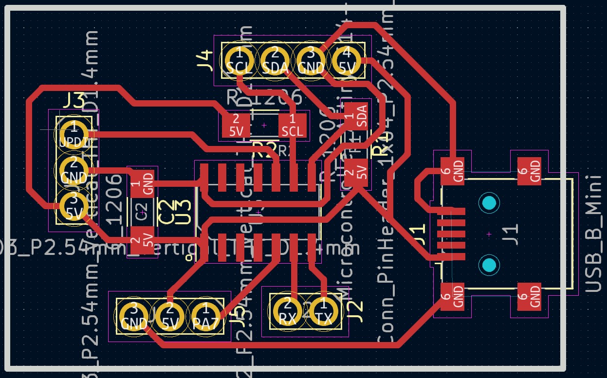
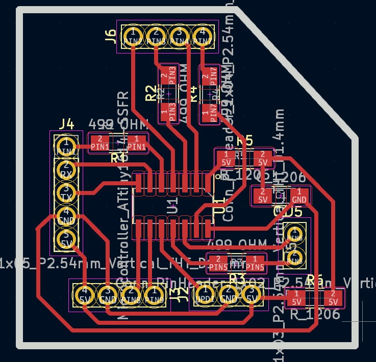
Here are the pin diagrams of my boards to know which are the pins to connect (Master on the left and slave on the right):
Once the code was tested, it was decided to extend the matrix, seeking to collect information from the 40 holes involved in the final project.
So, I made 10 slaves boards (all similar in code except for their address) and developed the master that asks for information from each of the boards and prints it on the screen in the form of a vector with 40 ordered positions.
The developed code of the Master board is below:
        #include
          int triangulos[] = {
            0, 0, 0, 0,
            0, 0, 0, 0,
            0, 0, 0, 0,
            0, 0, 0, 0,
            0, 0, 0, 0,
            0, 0, 0, 0,
            0, 0, 0, 0,
            0, 0, 0, 0,
            0, 0, 0, 0,
            0, 0, 0, 0
          };

          int index;
          int contador_azules = 0;
          int contador_blancos = 0;
          int azules[4] = { 50, 50, 50, 50 };
          int blancos[4] = { 50, 50, 50, 50 };

          int vecinos[40][3] = {
            { 1, 4, 7 },   // vecinos de 0
            { 0, 2, 10 },  // ...
            { 1, 3, 13 },
            { 2, 4, 16 },
            { 1, 3, 19 },
            { 6, 19, 20 },
            { 5, 7, 22 },
            { 0, 6, 8 },
            { 7, 9, 24 },
            { 8, 10, 26 },
            { 1, 9, 11 },  // vecinos 10
            { 10, 12, 28 },
            { 11, 13, 30 },
            { 2, 12, 14 },
            { 13, 15, 32 },
            { 14, 16, 34 },
            { 3, 15, 17 },
            { 16, 18, 36 },
            { 17, 19, 38 },
            { 4, 5, 18 },  // vecinos de 19
            { 5, 21, 39 },
            { 20, 22, 100 },  // 100 no existe
            { 6, 21, 23 },
            { 22, 24, 100 },
            { 8, 23, 25 },
            { 24, 26, 100 },
            { 9, 25, 27 },
            { 26, 28, 100 },
            { 11, 27, 29 },
            { 28, 30, 100 },
            { 12, 29, 31 },
            { 30, 32, 100 },
            { 14, 31, 33 },
            { 32, 34, 100 },
            { 15, 33, 35 },
            { 34, 36, 100 },
            { 17, 35, 37 },
            { 36, 38, 100 },
            { 18, 37, 39 },
            { 20, 38, 100 }
          };


          void setup() {
            Wire.begin();        // join i2c bus (address optional for master)
            Serial.begin(9600);  // start serial for output
          }

          void loop() {
            leerTriangulo(1, 0);
            leerTriangulo(2, 4);
            leerTriangulo(3, 8);
            leerTriangulo(4, 12);
            leerTriangulo(5, 16);
            leerTriangulo(6, 20);
            leerTriangulo(7, 24);
            leerTriangulo(8, 28);
            leerTriangulo(9, 32);
            leerTriangulo(10, 36);

            for (int i = 0; i < 40; i++) {
              Serial.print(triangulos[i]);
              Serial.print(" , ");
            }
            Serial.println("");
            comprobar_azules();
            comprobar_blancos();
            delay(1000);
          }


          void leerTriangulo(int adress, int indiceInicial) {
            Wire.requestFrom(adress, 4);  // request 4 bytes from slave device #1
            index = indiceInicial;
            Serial.println(adress);
            while (Wire.available()) {  // slave may send less than requested
              int c = Wire.read();      // receive a byte as character
              Serial.println(c);
              triangulos[index] = c;
              index = index + 1;
            }
          }

          void comprobar_azules() {
            //comprobar fichas azules
            for (int i = 0; i < 40; i++) {
              if (triangulos[i] == 1 && (contador_azules < 4)) {  //1 azul, 2 blanco, 0 nada
                azules[contador_azules] = i;
                contador_azules++;                                                // contamos 1º azul
                for (int j = 0; j < 3; j++) {                                     // buscamos el 2º azul
                  if (triangulos[vecinos[i][j]] == 1 && (contador_azules < 4)) {  // buscar en los vecinos el valor
                    azules[contador_azules] = vecinos[i][j];
                    contador_azules++;  // contamos 2º azul
                    for (int k = 0; k < 3; k++) {
                      if ((triangulos[vecinos[vecinos[i][j]][k]] == 1) && (in_array(azules, vecinos[vecinos[i][j]][k])) && (contador_azules < 4)) {  // buscar en los vecinos el valor
                        azules[contador_azules] = vecinos[vecinos[i][j]][k];
                        contador_azules++;  // contamos 3º azul
                        for (int l = 0; l < 3; l++) {
                          if ((triangulos[vecinos[vecinos[vecinos[i][j]][k]][l]] == 1) && (in_array(azules, vecinos[vecinos[vecinos[i][j]][k]][l])) && (contador_azules < 4)) {  // buscar en los vecinos el valor
                            azules[contador_azules] = vecinos[vecinos[vecinos[i][j]][k]][l];
                            contador_azules++;  // contamos 4º azul
                          }
                        }
                      }
                    }
                  }
                }
              }
              if (contador_azules == 4) {
                Serial.print("Azul gana");
                for (int y = 0; y < 4; y++) {
                  Serial.print(azules[y]);
                  Serial.print(" ");
                }
                Serial.println("");
              } else {
                contador_azules = 0;
                for (int t = 0; t < 4; t++) {
                  azules[t] = 50;
                }
              }
            }
          }

          void comprobar_blancos() {
            //comprobar fichas blancos
            for (int i = 0; i < 40; i++) {
              if (triangulos[i] == 1 && (contador_blancos < 4)) {  //1 blanco, 2 blanco, 0 nada
                blancos[contador_blancos] = i;
                contador_blancos++;                                                // contamos 1º blanco
                for (int j = 0; j < 3; j++) {                                     // buscamos el 2º blanco
                  if (triangulos[vecinos[i][j]] == 1 && (contador_blancos < 4)) {  // buscar en los vecinos el valor
                    blancos[contador_blancos] = vecinos[i][j];
                    contador_blancos++;  // contamos 2º blanco
                    for (int k = 0; k < 3; k++) {
                      if ((triangulos[vecinos[vecinos[i][j]][k]] == 1) && (in_array(blancos, vecinos[vecinos[i][j]][k])) && (contador_blancos < 4)) {  // buscar en los vecinos el valor
                        blancos[contador_blancos] = vecinos[vecinos[i][j]][k];
                        contador_blancos++;  // contamos 3º blanco
                        for (int l = 0; l < 3; l++) {
                          if ((triangulos[vecinos[vecinos[vecinos[i][j]][k]][l]] == 1) && (in_array(blancos, vecinos[vecinos[vecinos[i][j]][k]][l])) && (contador_blancos < 4)) {  // buscar en los vecinos el valor
                            blancos[contador_blancos] = vecinos[vecinos[vecinos[i][j]][k]][l];
                            contador_blancos++;  // contamos 4º blanco
                          }
                        }
                      }
                    }
                  }
                }
              }
              if (contador_blancos == 4) {
                Serial.print("Blanco gana");
                for (int y = 0; y < 4; y++) {
                  Serial.print(blancos[y]);
                  Serial.print(" ");
                }
                Serial.println("");
              } else {
                contador_blancos = 0;
                for (int t = 0; t < 4; t++) {
                  blancos[t] = 50;
                }
              }
            }
          }

          bool in_array(int array[], int value) {
            for (int m = 0; m < 4; m++) {
              if (array[m] == value) {
                return true;
                break;
              }
            }
            return false;
          }
The developed code of each slave is below:
#includeint triangulos[] = { 0, 0, 0, 0 }; int pin1Triangulos[] = { 1, 3, 8, 10 }; int pin2Triangulos[] = { 2, 4, 9, 0 }; unsigned long previousMillis = 0; // will store last time LED was updated const long interval = 500; // interval at which to blink (milliseconds) void setup() { Wire.begin(1); //This code is for the board 1 Wire.onRequest(requestEvent); // put your setup code here, to run once: Serial.begin(9600); } bool check(int pin1, int pin2) { pinMode(pin1, INPUT_PULLUP); pinMode(pin2, OUTPUT); digitalWrite(pin2, LOW); if (digitalRead(pin1) == 0) { return true; } else { return false; } } void ledOn(int pin1, int pin2) { pinMode(pin1, OUTPUT); pinMode(pin2, OUTPUT); digitalWrite(pin1, HIGH); digitalWrite(pin2, LOW); } void loop() { for (int i = 0; i < 4; i++) { if (triangulos[i] == 0) { if (check(pin1Triangulos[i], pin2Triangulos[i])) { triangulos[i] = 1; Serial.print("Connected pos "); Serial.println(1); ledOn(pin1Triangulos[i], pin2Triangulos[i]); } else if (check(pin2Triangulos[i], pin1Triangulos[i])) { triangulos[i] = 2; Serial.print("Connected pos "); Serial.println(2); ledOn(pin2Triangulos[i], pin1Triangulos[i]); } } else { unsigned long currentMillis = millis(); if (currentMillis - previousMillis >= interval) { // save the last time you blinked the LED previousMillis = currentMillis; if (triangulos[i] == 1) { Serial.print("triangulo "); Serial.println(i); Serial.println("Cheking 1"); if (!check(pin1Triangulos[i], pin2Triangulos[i])) { triangulos[i] = 0; } else { ledOn(pin1Triangulos[i], pin2Triangulos[i]); } } else if (triangulos[i] == 2) { Serial.print("triangulo "); Serial.println(i); Serial.println("Cheking 2"); if (!check(pin2Triangulos[i], pin1Triangulos[i])) { triangulos[i] = 0; } else { ledOn(pin2Triangulos[i], pin1Triangulos[i]); } } } } } } void requestEvent() { for (int i = 0; i < 4; i++) { Wire.write(triangulos[i]); } }
Each position is specified on the project development page which one it is and which one it corresponds to with each pair of pins.
This week, only one board was tested. So, this board 0 holds the positions of the triangles 0, 1, 2 and 3. The video below shows how the boards work and how the two placed LEDs are printed on the screen in positions 0 and 2. You can also see how changing the position of the LED poles causes a 1 or a 2 to appear in the vector displayed on the computer's serial.
The communication protocols used this week (in this last example) and which will be used in the final project are:
- UPDI, explained above, for programming the ATtiny as they cannot communicate directly with the computer. In this case, a SAMD11C14 microcontroller was used as a bridge to the ATtiny's UPDI.
- The I2C protocol. To communicate the master board with the slave board. In this case, we can see in the diagram of the boards how I left free the 4 pins corresponding to 5V, GND, SDA and SCLA that must be joined from one board to another to exchange data.
Rx and Tx (actually only Tx) to send and screen print the information from the ATtiny (the master board) via SAMD (without this it is not possible to print via the serial). In this case, the master board also has the Tx and Rx outputs and they correspond to pin 5 and 4 respectively on the SAMD11C14.
Files
Here are all the files used in the development of my project:
The Slave in KiCad.
I also include some tests of the evolution of the code with the final project in mind:
Group assigment
This week we send a message between two projects. The group task can be viewed at Group Assigment page.
Conclusions
This week we have learnt how ...