Week 8. Embedded Programming
Before the Start
Introduction 🖊
This week relates to programming. We will learn how to code and programm our PCBs in order to use them for our final/future projects.
I did some research about Arduino projects and I have already written down some new ideas I would like to try out using this week’s knowledge!
Fab Assignments 📚
-
Group assignment:
- Compare the performance and development workflows for other architectures
- Document your work to the group work page and reflect on your individual page what you learned
-
Individual assignment:
- Read the datasheet for your microcontroller
- Use your programmer to program your board to do something
My Goals 🎯
- What I think I already know
- During my bachelor’s program I learned the basics about programming with C++.
- What I want to learn
- Refresh my previous knowledge about programming
- Code and program my PCB
Project Management
How I’m going to organize my work during the week.
| Task | Time | Day |
|---|---|---|
| Research | 3h | 16, March |
| Group Assignment | 6h | 17, March |
| Design a PCB | 3h | 17, March |
| Milling PCB | 1h | 18, March |
| Soldering PCB | 1h | 18, March |
| Read the Data sheet | 4h | 19 / 20 March |
| Program board with Arduino IDE | 8h | 18 / 19 / 20, March |
| Documentation | 10h | 18 / 19 / 20, month |
Research
Youtube videos about Arduino’s projects
- Nils Völker - One Hundred and Eight, Responsive Installation 2010
- Responsive Kinematics
- 400 umbrellas programmed to dance like birds
- Wood Pixeles Screen made with Arduino
- 15 Great Arduino Projects for beginners
- Led Cubo with Arduino
Other student’s work
During the Process
Results 🖖
Group Assignment Process 🏊♀️ 🏊🏾 🏊🏽♀️
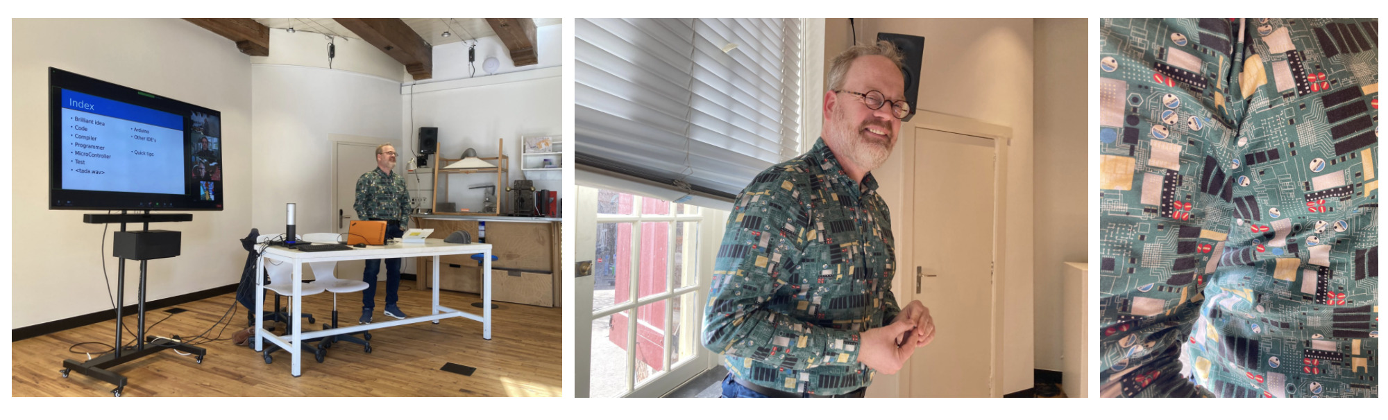
We started the week with a new marvelous lesson by Erwin. I always enjoy them very much! He is such a great teacher.
This time he also brought a really fancy shirt made of a PCB pattern. Fan of him!
During the lesson, We have been introduced to the following topics:
Code
Coding allows humans to translate our ideas into functions. In order to code, its needed an IDE (Integrated Development Environment).
Nowadays, exists a huge range of codes to program, allowing humans to develop very different kinds of projects. This diversity, also allows beginners to get into the coding world, being able to develop simple lines to make - for example - LEDs bright in a PCB board like we will do during the group assignment task.
C
One of the first developed coding systems is called “C”, which is a binary code. This makes “C” a program close to the machines, and far from the understanding of humans.
C+
The next generation of “C” is “C++”. A code that is easier to understand by humans beings and which is the code used when programming with Arduino.
MicroPython
Probably the most extended code when programming apps or interfaces in Python. This code needs a high level of knowledge to be understood.
RTOS
Real-Time Operating System is an operating system (OS) for real-time applications that process data and events which are task-oriented and have task-priorities.
An example of an RTOS is the opening/closing of the train’s doors. When closing the doors before the departure, there are different tasks which the train needs to do, such as making sound, brightening the buttons lightly, and closing the door itself. These events follow each other in task-line, and in case of need, closing the door will have priority in front of the previous ones in order to allow the train departure.
Compiler
Since codes developed into a more human-friendly version to be able to be coded and read by humans. When programming is needed a “Compiler” which translate human understable code to the machine-specific-code (binary).
Programmer
Once the code is transformed into machine-specific-code, is needed one step further to transfer the binary-code to the microcontroller. This step is allowed by the “Programmer”.
Microcontroller
Since one of the individual assignments for this week is to read the datasheet of the microcontroller we will use for our PCB - in oir case the ATiny412. Erwin showed us where to find the important info needed to design our board:
First of all, it is important to undertand the microcontroller’s schematic.
Arduino
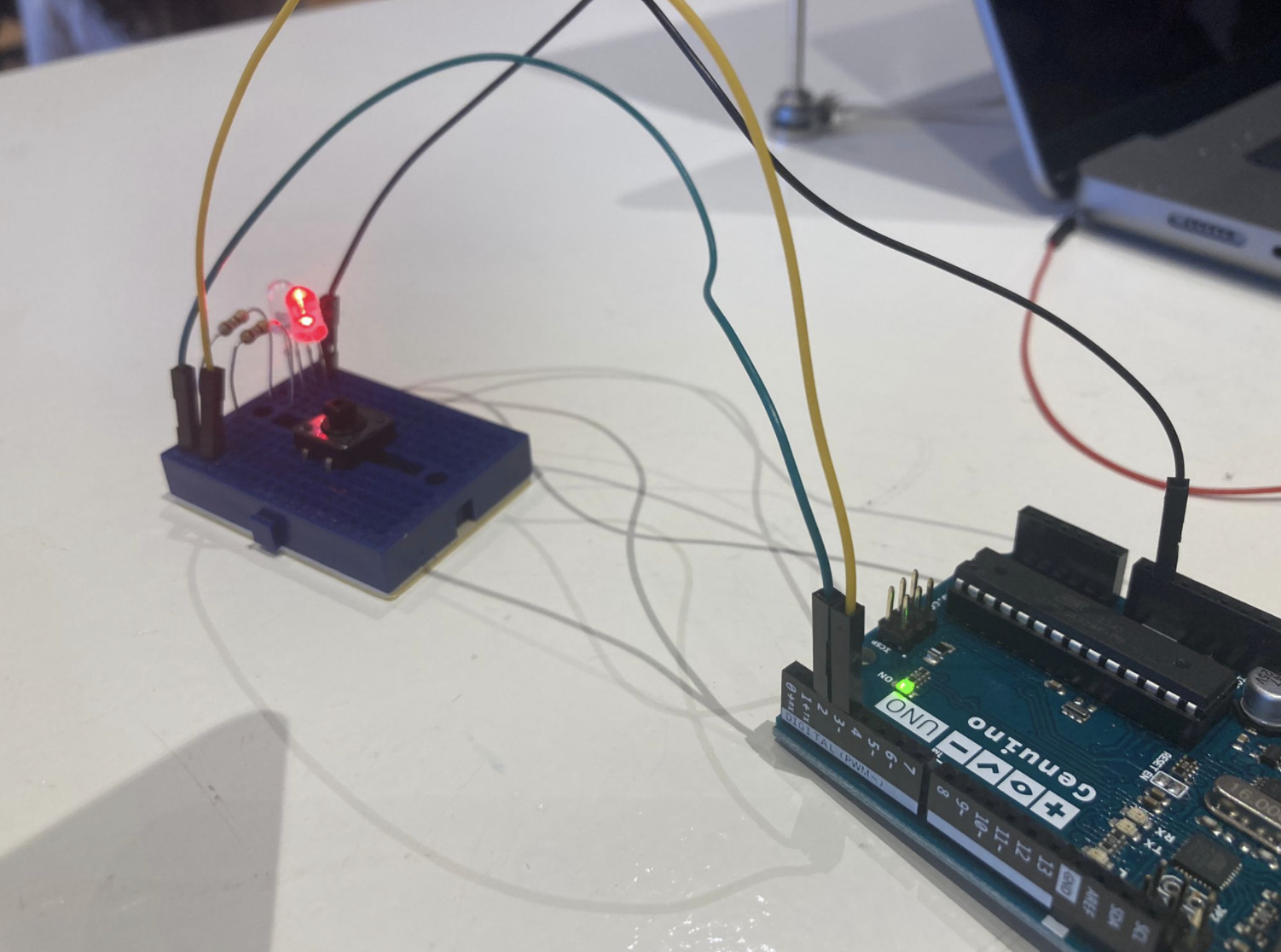
During the group assignment, we coded an Arduino board to start getting use to programming. We tried both the digital and the analogic board’s pins.
When running the Arduino program, this is the screen will show up.

| Part | Task | Location |
|---|---|---|
| Verify | It verifies the code and shows on the button valuable info about it. This is where errors will be shown | “✔️” symbol. At the left header’s side |
| Upload | It compilates the code and uploads it to the Arduino board | “->” symbol. At the left header’s side |
| Void Setup | Where the OUTPUTS and INPUTS of the board are set up. When adding them, it is needed to add the pin to which for example the LED is connected | First line of the Arduino’s code |
| Void Loop | Where the code is written down. Here it is possible to do a 1 linear code, or multiple loops. | A few lines below the “void setup” line |
| // Text | This parameter allows the user to write down comments next to the lines, or inactivate some parts when needed. Tip 🛎️: Write a clear description in order to undestand when coming back to the code what you did | Next to the code lines |
Firt thing to do is to set up the board it will be used. Follow this path to do it:
Tools > Board > ... select your board
In this case, we used the board named: Arduino UNO
When using Arduino, it is needed to connect with wires the INPUTS and OUTPUTS with the board. Attached a tip from Erwin when connecting the wires:
Erwin’s Tip 🛎️: Connect the wires in this way: - Red = to the pin - Balck = to the ground - Green = to the led
Bright 1 LED - pin nº5
First, we tried to make bright one LED connected to the PIN N5. This is the code we used:
void setup()    {
    pinMode(5, OUTUP);
}

void loop() {
    digitalWrite(5, HIGH);
}
Bright 2 LEDs - pin nº5 & pin nº6
void setup()    {
    pinMode(5, OUTPUT);
    pinMode(6, OUTPUT);

}

void loop() {
    digitalWrite(5, HIGH);
    digitalWrite(6, HIGH);
}
Both LEDs will be bright with the same intensity at the same time.
Alternate the bright 2 LEDs - pin nº5 & pin nº6
Add a new line with
void setup()    {
    pinMode(5, OUTPUT);
    pinMode(6, OUTPUT);

}

void loop() {
    digitalWrite(5, HIGH);
    digitalWrite(6, LOW);
    delay(100);
    digitalWrite(5, LOW);
    digitalWrite(6, HIGH);
    delay(100);
}
The LEDs will alternate their bright with a delay of 100. The difference is not so clear, so we repeated the experiment doing a delay of 500.
void setup()    {
    pinMode(5, OUTPUT);
    pinMode(6, OUTPUT);

}

void loop() {
    digitalWrite(5, HIGH);
    digitalWrite(6, LOW);
    delay(500);
    digitalWrite(5, LOW);
    digitalWrite(6, HIGH);
    delay(500);
}
This time the flickering was more obvious.
Add and Read Button options
Now we want to set up a button, which we can use to make bright or not the LEDs when it is pressed.
When using “==” means “if”.
void setup()    {
    pinMode(5, OUTPUT);
    pinMode(6, OUTPUT);
    pinMode (2, INPUT_PULLUP);

}

void loop() {
    if(digitalRead(2) == LOW) {
    digitalWrite(5, HIGH);
    digitalWrite(6, LOW);
    }  else {
    digitalWrite(5, LOW);
    digitalWrite(6, HIGH);
    }
}
With this code, it is possible to make bright the LED connected to pin 5 just when pressing the button. When the button is not pressed, the LED connected to point 6 will be brightening.
Add Analogic regulator
When using analog INPUTS, is important to add both the INPUT and an the OUTPUT in the code. This is because the analog INPUT is reading a value, which needs to be shown somewhere. What We do is adding an introduction line to read the value, and then a second lime to place where is going to show it.
In our example, the INPUT is an regulator - useful for example to regulate the music in a speaker - which will show numbers as OUTPUTS.
void setup()    {
    pinMode(5, OUTPUT);
    pinMode(6, OUTPUT);
    pinMode (2, INPUT_PULLUP);
    pinMode (A0, INPUT);

    Serial.begin(9600);

}

void loop() {
    if(digitalRead(2) == LOW) {
    digitalWrite(5, HIGH);
    digitalWrite(6, LOW);
    }  else {
    digitalWrite(5, LOW);
    digitalWrite(6, HIGH);
    }

potRead = analogRead(A0);
serial.println(potRead);

}
To see the output numbers, follow this path:
Tools > Serial Monitor
To see the output into a graph, follow this path:
Tools > Serial Plotter
Regulate the intensity of the LED pin 2 with an analog INPUT
void setup()    {
    pinMode(5, OUTPUT);
    pinMode(6, OUTPUT);
    pinMode (2, INPUT_PULLUP);
    pinMode (A0, INPUT);

    Serial.begin(9600);

}
void loop() {
potRead = analogRead(A0);
potRead = map(potRead, 0, 1023, 0, 225); // Here I make a relation between the analog regulator and the LEDs intensity
analogWrite(5, potRead);
}
Individual Assignment Process 🏊♀️
Read the ATiny 412 microcontroller
Since the Data Sheet of the ATiny 412 microcontroller is quite extensive. I decided to follow the tips from Erwin and only look to the data useful in order to design my board.
Block Diagram
Starting from the beginning, this is how it looks like the ATiny 412 Hardvard Arquitecture:
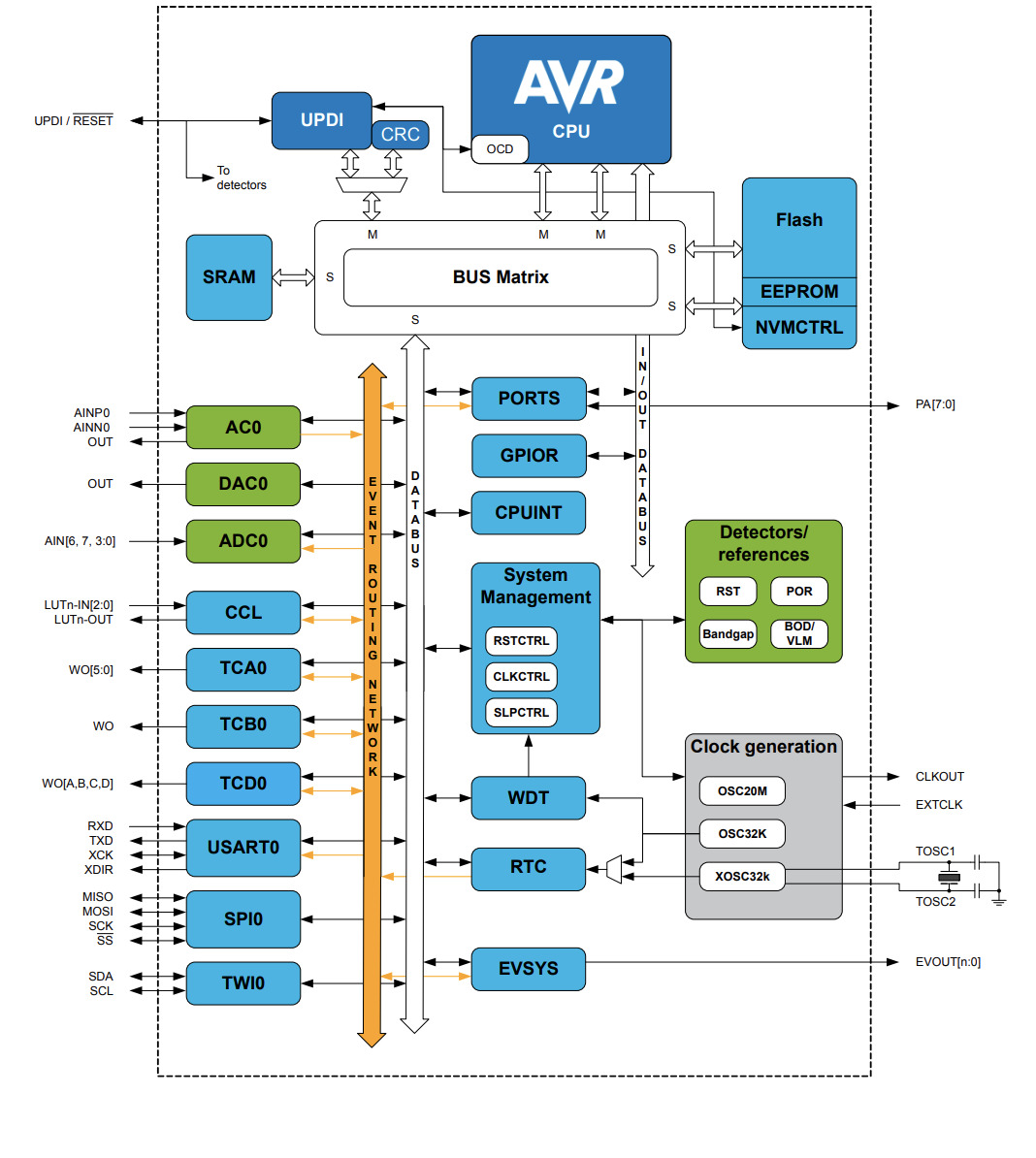
The green parts show the INPUTS and OUTPUTS pin connections, and the data bus white arrow show the dirrection of the internal communication within the microcontroller.
Pinout
It is important to understand how the pins work, which are their purposes, etc in order to find that info, I looked to page 13, where there is a nice scheme explaining where to connect INPUTS and OUTPUTS.
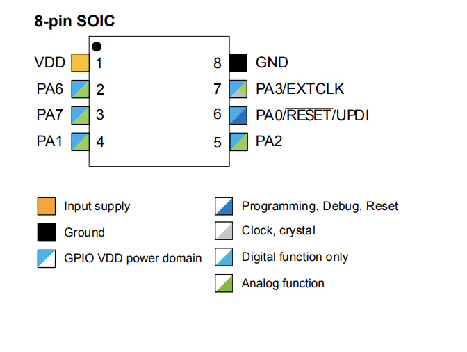
The PINS which I will be able to use for the design of my new individual assignment board are PA1, PA6, PA7, PA3, and PA2.
Tip 🛎️: When coding your board, the naming for each PIN will be A1, A2, etc instead of PA1, PA2.
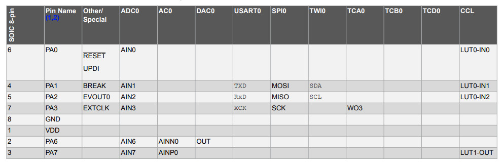
I/O Multiplexing and Considerations
The table shown on page 14, is very handy when designing the board’s PINS. In it, info required to locate the levels is shown, as an example, the TX and RX will be located in the PA1 and PA2.
Those are the questions which I answered:
PORT - I/O Pin Configuration
Staring from page 105, it can be found all the needed data about INPUT and OUTPUT configurations.
This info is very handy when choosing which INPUTS (ex. button) or OUTPUTS (ex. LEDs) use to design a board, and how they work.
When starting the code, it will be always needed to define both INPUTS and OUTPUTS and the PINS associate to each one of them.
When configurating a mircocontroller, it is just need to set up the parts you are going to use. Don’t need of configurate the pins you will not use.
16.5.2 the Data direction set if is an imput or output. If its 0 is imput, if its 1 its output.
What I need for my final project?
During this week, I planned which are the elements that I will need to use when programming the board for my final project. Those are:
- A LED will turn ON/OFF when the motor is working and push the material from the deposit to the nozzle;
- A button to start the motor;
- A speaker which will make a sound when the material is over before the motor stops.
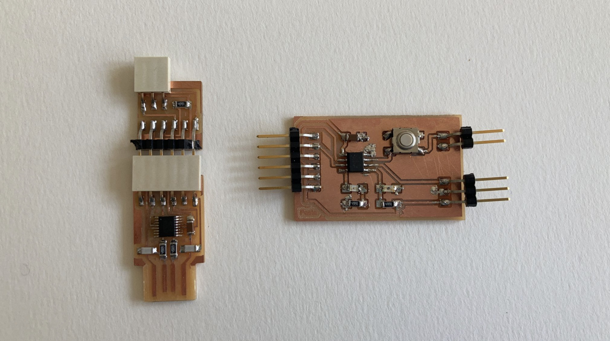
Design New Hello World Board
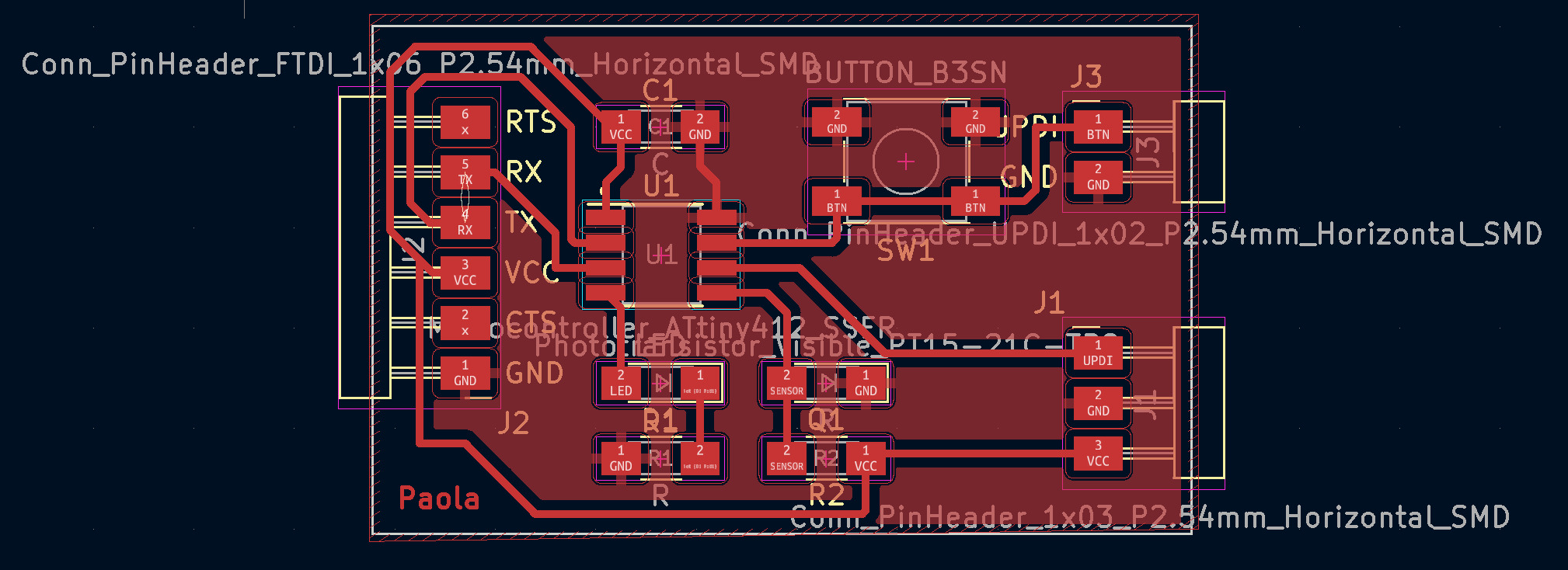
I re-designed my Hello World board with KiCad, mill it, solder its components and program it again during this week.
During the design process with KiCad, I did not found much difficulty. This is the picture of the result:
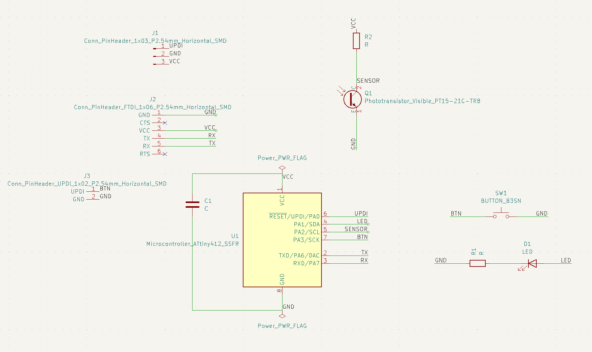
I corrected all the mistakes which I did during the Electronics Design Week, and added a new 2 pin connection to my board’s button.
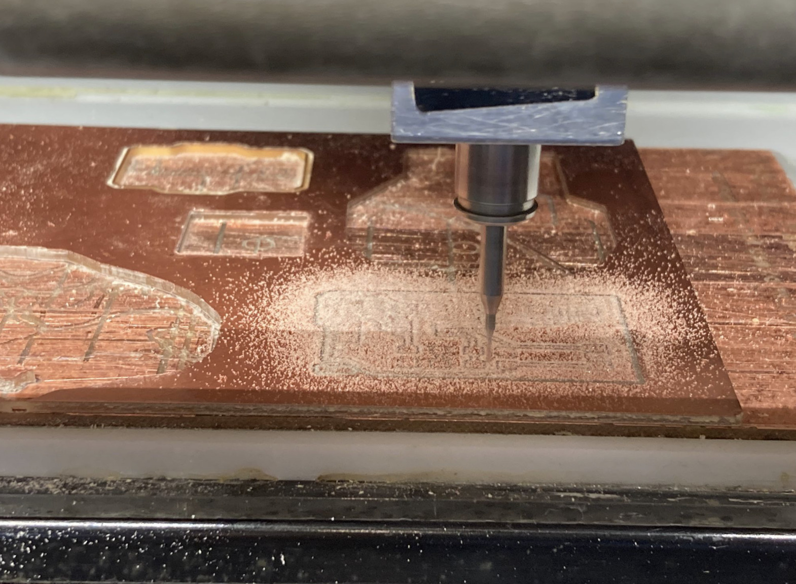
Milling
When preparing the files for the milling, I had some troubles - specially with the editing of the outlines file.
The kicad version which I have installed on my MacBook (6.0.1) is exporting the files with a huge white artboard around the design, which is a problem when uploading and milling the draw with mods since it is difficult to set up the draw’s origin.
I tried to use Inkscape to edit the files in order to correct the artboard problem, but again the version installed on my computer was giving troubles, so I conclude that Mac is not optimal to use with this program and I used Waag’s computers to export and edit my design files.
I also did a mistake when uploading the file on Mods. Since I did not select the option “fill background” before inverting the image of my board, the program was not reading the right part of the trace’s draw.
Soldering
Once I fixed this pre-milling problem, I did not have any further trouble when milling and soldering the components to the board.
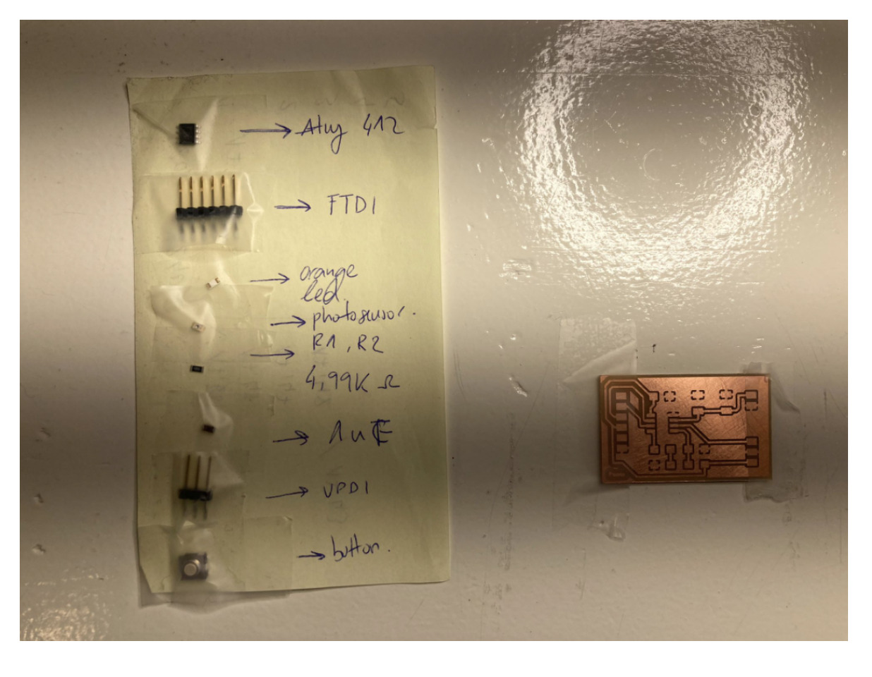
Even though, I did realize when trying to program my board, that I actually added too much soldering to the capacitor of my board, the trace which connects the VCC from the UPDI to the microcontroller was touching the ground. I fixed it removing the Capacitor and soldering it again using less soldering material.
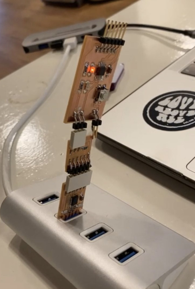
Programming the Board
When programming the board, I already had ready from the Electronics Production week my programmer PCBs. I used them to upload Niel’s code on my Hello World Board.
#define max_buffer 25

static int index = 0;
static char chr;
static char buffer[max_buffer] = {0};

void setup() {
Serial.swap(1);
Serial.begin(115200);
}

void loop() {
if (Serial.available() > 0) {
    chr = Serial.read();
    Serial.print("hello.t412.echo: you typed \"");
    buffer[index++] = chr;
    if (index == (max_buffer-1))
        index = 0;
    Serial.print(buffer);
    Serial.println("\"");
    }
}
But before I was able to do that, I had to configure Arduino IDE in order to be able to use it with the ATiny 412 microcontroller which I used to design my board. To do that, I followed this steps:
I did open Arduino IDE, and followed this path:
Arduino > Preferences ...
Here I added this link to the Additional Boards Manager and selected the options: “Compilation” and “Upload” to make it work
http://drazzy.com/package_drazzy.com_index.json
Then I navigated to:
Tools > Boards > Boards Manager ...
and installed the Mega Tiny Core, typing: Megatinycore on the finder.
Now Arduino IDE was ready to use with my board.
I did try the following codes to make blink the LED of my board:
void setup() {
    pinMode(A1, OUTPUT);
}
void loop() {
digitalWrite(A1, HIGH);
delay(500);
digitalWrite(A1, LOW);
delay(30);
}
Here I played for a while with the delay and made some light games.
Then I tried this code in order to make the button work:
const int buttonPin = A3;
const int ledPin = A1;
int buttonState = 0;

void setup() {
pinMode(A1, OUTPUT);
pinMode(A3, INPUT);
}

void loop() {
buttonState = digitalRead(A3);
if (buttonState == HIGH) {
    digitalWrite(A1, HIGH);
} else {
    digitalWrite(A1, LOW);
}
}
Retrospective 🤔
This week I learned how much I actually like to code.
During my bachelor’s, I had a course dedicated to learning C++. I remember I use to enjoy it, but it was not between my favourite subjects.
Now I understand that the reason why I was not so attracted to it, was because of the way of learning it.
Back then, our tasks were solving math problems, never seeing tangible outcomes from it - behind the “compilation error screen”.
As a Designer, I love to analyze tangible end solutions to problems. Making blink LEDs, working a button, or regulating the music sound with analog input, motivates me much more to learn about coding and use it in my future projects.