Week 13. Networking and Communications
Before the Start
Introduction 🖊
This week belongs to Networking and Communications projects. In terms of electronics, this means creating communication channels with wires or wireless between different systems.
Fab Assignments 📚
-
Group assignment:
- Send a message between two projects
-
Individual assignment:
- Design, build, and connect wired or wireless node(s) with network or bus addresses
My Goals 🎯
-
What I think I already know
- Not previous experience in this field
-
What I want to learn
- Learn the theory behind the field and make the individual assigment
- I cannot use the assignment for my final project. So I will use my time on making the assignment and focus on the final project development.
Project Management
How I’m going to organize my work during the week.
| Task | Time | Day |
|---|---|---|
| Research | 3h | 27, April |
| Group Assignment | 6h | 28, April |
| Individual Assignment | 2h | 29, April |
| Documentation | 2h | 29, April |
Research
I did research the following websites to get a deeper understanding of Networking projects made with Arduino boards, and how to apply the new knowledge in my individual assignment:
During the Process
Results 🖖
Group Assignment Process 🏊♀️ 🏊🏾 🏊🏽♀️
Serial Communication Protocol
In terms of electronics, a Serial Communication Protocol means to send data in a line of data after each other. This kind of data is considered digital data.
The problem with this kind of data communication is that it takes a long time to be transmited.
Clock
The data can be sent in a syncronous and an asyncronous way. Depending of that, we can find different kind of serial communication methods:
UART
Universal Asynchronous Receiver Transmitter This way of communication uses just 1 cable + the ground reference.
I2C
Inter-Integrated-Circuit
This is synchronous communication. It needs two connections + the ground reference. One wire will send the data, its name is SDA. The second wire will be the clock and it will be called SCL.
Each receiver has an address, so when sending data first it is needed to set up the address, and secondly to add the data.
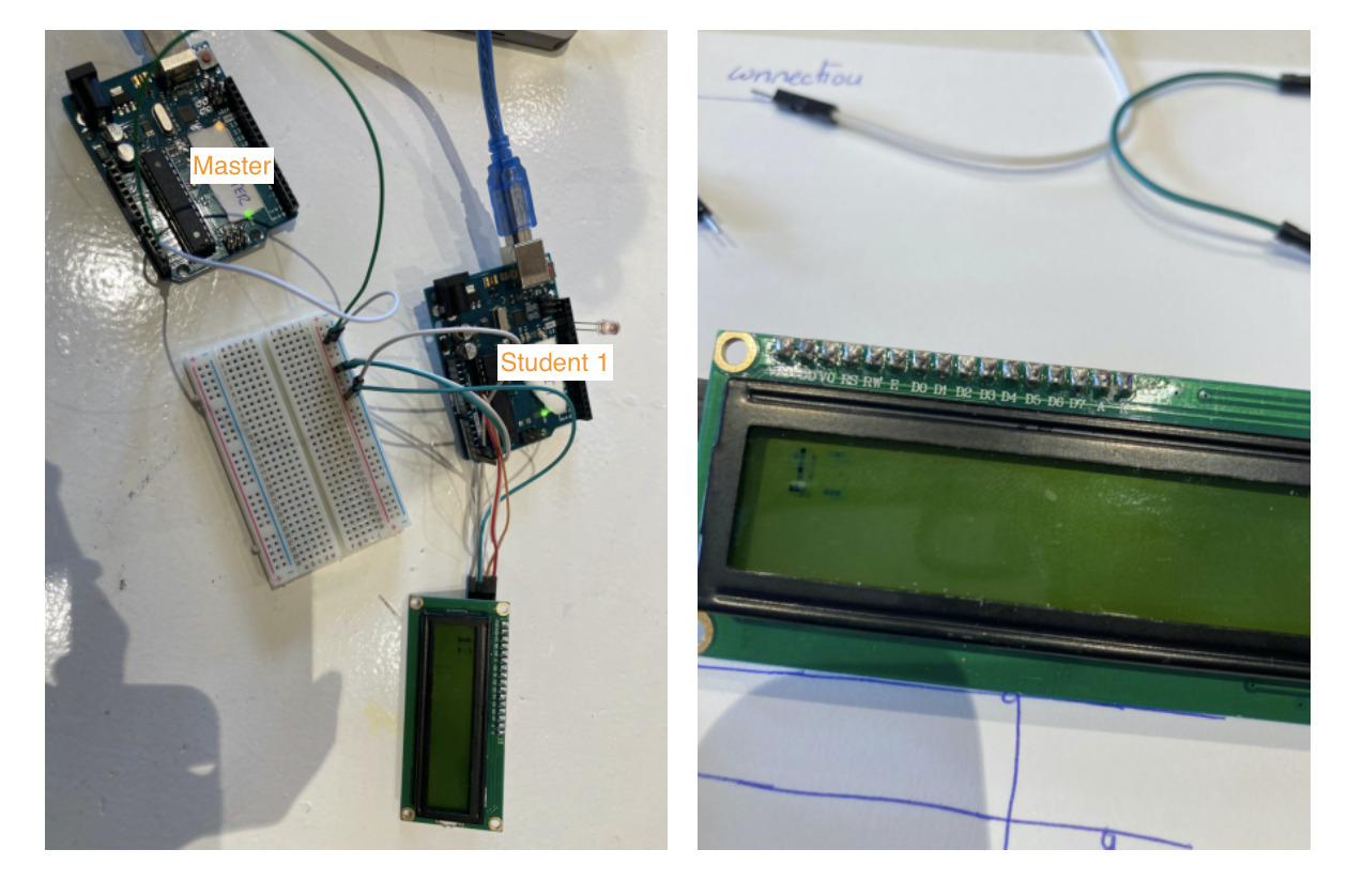
During the Group Assigment, we tried this protocol to send data between two Arduino boards.
SPI
Serial Periphelian Interface
It has 3 wires + the clock connection:
- MOSI: the master output slave;
- MISO: master input slave;
- SS: chip select wire;
-
- ground reference.
This protocol can send data but also received it. In order to do that, it does not necessity the address like in the I2C because it has the chip selected.
Individual Assignment Process 🏊♀️
During the individual Assignment, I decided to send data using the I2C protocol between two Arduino boards, using a crystal screen to show the data.
This is the steps that I followed in order to accomplish the assignment:
Some Theory
This kind of protocol was developed by Philips to send internal data between its electronics devices.
The device which will be used as Master is the one that subministrates the clock to the rest of the network.
When using Arduino boards, depending on the type those are the connections required to make the hardware:
| Type | SDA | SCL |
|---|---|---|
| UNO | A4 | A5 |
| MEGA | 20 | 21 |
| MINI PRO | A4 | A5 |
| NANO | A4 | A4 |
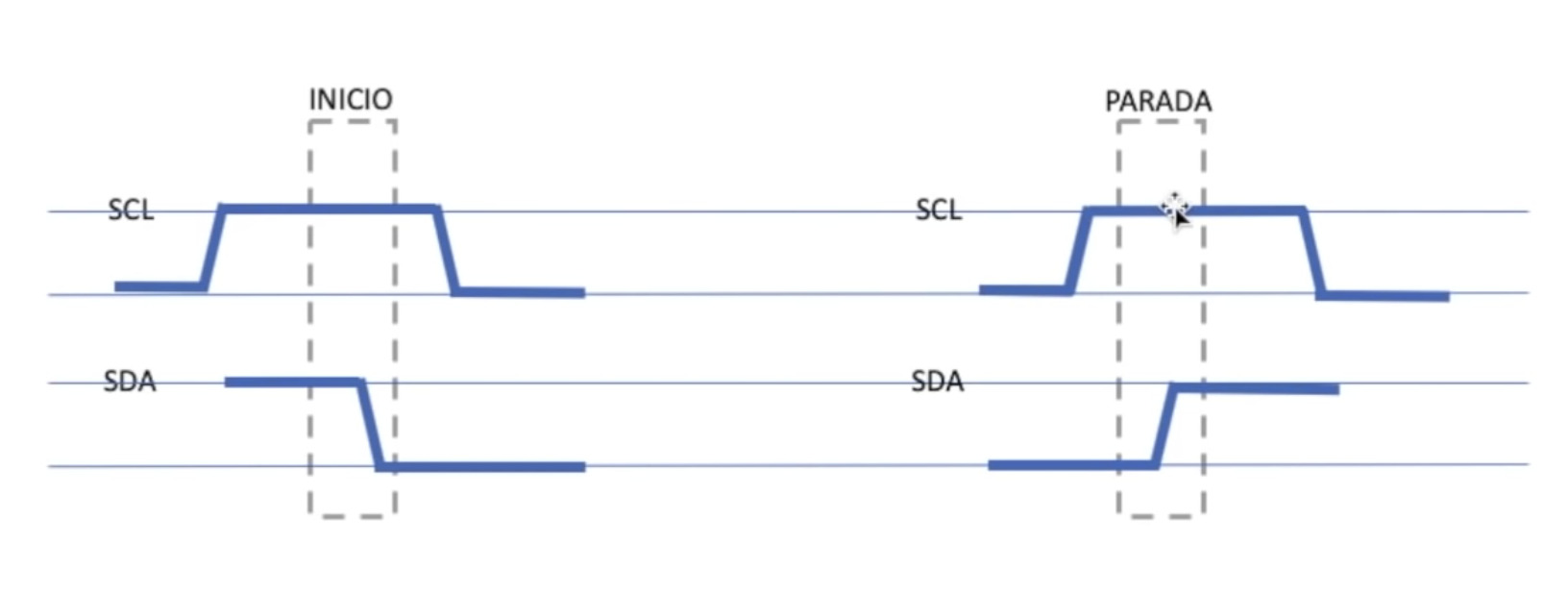
The signal sent by the SCL changes depending on if it starts or stops the communication between the network - look attached photo. The signal sent by the Data is like a pulse, and it can be sent both from the Master to the Slaves and to the Slaves to the Master.
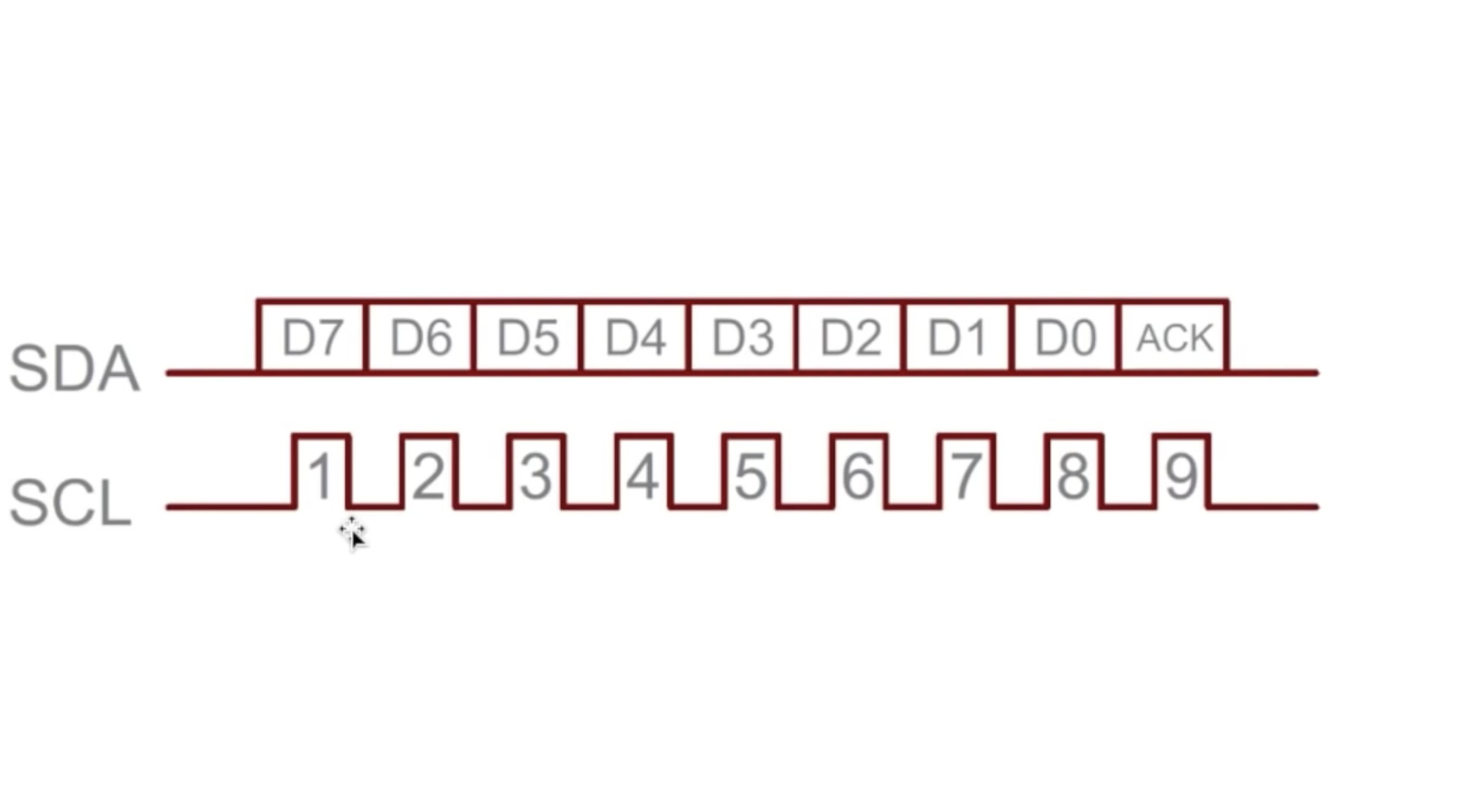
When the Master starts a communication with the network, the signal of the clock is high, and it stays high when the signal sent by the data is low. When the communication stops, the signal sent by the clock is high, and the one sent by the data is also high.
Hardware
Once I understood how the communication works using the I2C protocol, I used two Arduino boards to set up the hardware needed to make it work.
Attached in the photo is the resulting hardware.
Coding
In order to make the code, I printed on the screen a sequence of a few numbers from 9 to 13.
Attached is the code I used to make it work.
To make it work, I firstly needed to add the <LiquidCrystal_I2C.h> library. It did not work the first time, so I needed to download multiple libraries.
The address of the crystal screen was lcd(0x27,16,2), I did tried a few combinatios before getting it.
Master Code
#include <Wire.h>
#include <LiquidCrystal_I2C.h>
LiquidCrystal_I2C lcd(0x27,16,2);

byte pin[] = {9, 10, 11, 12, 13}; // send sequence of numbers to be printed
byte estado = 0;
byte retardo = 100;
int ValorSensor = 0;

void setup() {
pinMode(3,INPUT);
Wire.begin();
lcd.init();
lcd.backlight();
lcd.clear();
lcd.setCursor(0,0);
}

void loop() {
for (int i = 0; i < 5; i++) // Send sequence of 5 steps
{
    Wire.beginTransmission(1);  // Student 1
    Wire.write(estado);
    Wire.endTransmission(); // Stop Student 1

    lcd.setCursor(0,0); // Screen
    lcd.print(pin[i]); // Send numbers to the screen from 1 to 5
    lcd.print(" ");

    delay(retardo);
}

if (estado == 0)
{
    estado = 1;
}
else
{
    estado = 0;
}

}
Student Code
// Code Student 1
#include <Wire.h>

void setup() {
// Pines en modo salida
pinMode(13, OUTPUT);
pinMode(12, OUTPUT);
pinMode(11, OUTPUT);
pinMode(10, OUTPUT);
pinMode(9, OUTPUT);

// Join this device to the I2C bus with address 1 (Student 1)
Wire.begin(1);

// Register the event when receiving data
Wire.onReceive(llegaDato);

}

void loop() {
delay(30);
}

// Function that is executed whenever data is received from the master
void llegaDato() {

int pinOut = 0;
int estado = 0;

// If two bytes are available
if (Wire.available() == 2)
pinOut = Wire.read();
if (Wire.available() == 1)
    estado = Wire.read();


// Activate/deactivate output
digitalWrite((pinOut),estado);
}
Networking and Communications with my Hello World board
During the development of this assignment, I did the individual assignment using two Arduino boards to test the process.
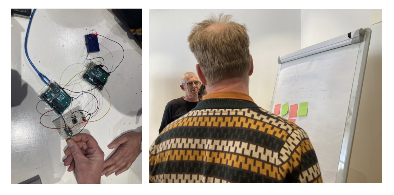
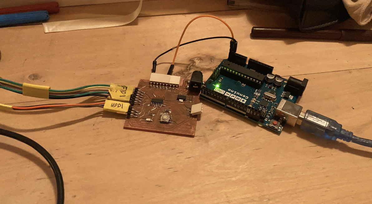
I re-made the assignment using the board which I designed for my final project. Attaching the system in the same way as previously explained for the Arduino boards I2C, using as Master my Hello World board, as a Student an Arduino board where a led blinks every time there is a communication with it.
Attached is the picture of the Hardware of the Hello World + Arduino boards:
The master’s code which i used to make the communication I2C between the boards is the following one:
#include <Wire.h>

#define NODE_ADDRESS  0x42

void setup() {
Serial.begin(9600);
Wire.begin();
Serial.write("Setup done..");
}

void loop() {
Serial.write("Sending request..");
Wire.requestFrom(NODE_ADDRESS, 1);

while (Wire.available()) { // peripheral may send less than requested
    int c = Wire.read(); // receive a byte as character
    Serial.print(c);         // print the character
}
Serial.print("\n");

delay(1000);
}
The code for the Student is the attached one:
#include <Wire.h>
#define NODE_ADDRESS  0x42

const int ledPin = 13;
int ledState = LOW;

void setup() {
pinMode(13, OUTPUT); // Led 13 blinks

Wire.begin(NODE_ADDRESS);
Wire.onRequest(dataRequest);

}

void loop() {
delay(30);
}

// Function that is executed whenever data is received from the master
void llegaDato() {

int pinOut = 0;
int estado = 0;

// If two bytes are available
digitalWrite(ledPin, ledState);

if (Wire.available() == 2)
pinOut = Wire.read();
pinMode = HIGH;
if (Wire.available() == 1)
estado = Wire.read();
pinMode = LOW;

}
Retrospective 🤔
This week resulted on being puzzling. Understanding much better how connections between systems are made, and how for example wifi works was really interesting.
I am also happy to learn that the language originally developed to talk about its components: master & slave is changed for a more inclusive one in the development of the Fab Academy.
I could not use the new learnings for my final project, but even though I had a lot of fun learning the theory behind the networking and communication process, and being able to test it both with Arduino and my Hello World board.