Week 12. Input Devices
Introduction 🖊
This week belongs to Input Devices. We will learn how different kind of sensors works. Inputs devices are very handy when wanting to make interactive projects, using for example distance/movement sensors.
Fab Assignments 📚
-
Group assignment:
- Probe an input device(s)’s analog and digital signals.
- Document your work to the group work page and reflect on your individual page what you learned.
-
Individual assignment:
- Measure something: add a sensor to a microcontroller board that you have designed and read it.
My Goals 🎯
- What I think I already know:
- I don’t have previous experience working with input devices.
- What I want to learn:
- Success in the individual assignment trying a distance sensor.
- Implement and try an input device for my final project.
Project Management
How I’m going to organize my work during the week.
| Task | Time | Day |
|---|---|---|
| Research | 3h | 20, April |
| Group Assignment | 5h | 21, April |
| Individual Assignment | 2h | 21, April |
| Documentation | 3h | 22, 25 April |
Research
I did researched the following websites and videos to learn how input devices work, and how to use and program them:
- How to Use Temperature and Humidity (DHT) Sensors
- DHT11 & DHT22 Sensors Temperature and Humidity Tutorial using Arduino
- Temperature Sensors Explained
- Heart Pulse sensor
- Pulse Sensor Servo Tutorial
During the Process
Results 🖖
- Add photos or/and videos of the Week’s assignments.
Group Assignment Process 🏊♀️ 🏊🏾 🏊🏽♀️
We started the group assignment with another great introduction by Erwin.
Erwin introduced us to the following concepts during his lesson:
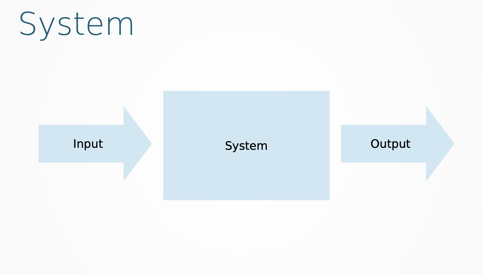
In a circuit, inputs devices are those elements that give data to the system. The data is read and shown by using different kinds of interfaces.
Digital Vs. Analog
There are two types of input devices:
- Analog:
- The physical unit is converted to a resistance, capacitance or current (then to voltage)
- Values are sampled (taken over time)
- Digital:
- The physical unit is converted in opening or closing a circuit
Interfaces
ADC
In electronics, an analog-to-digital converter (ADC, A/D, or A-to-D) is a system that converts an analog signal, such as a sound picked up by a microphone or light entering a digital camera, into a digital signal.
When working with an ADC interfaces, it needs to be taken the following considerations:
- 8-bit (0-255), 10-bit (0-1023), 12-bit (0-4095)
- More bits, more resolution
When programming with ADC interfaces, it is use the following value:
- Value = AnalogRead(pin);
GPIO
GPIO stands for General Purpose Input/Output. It’s a standard interface used to connect microcontrollers to other electronic devices. For example, it can be used with sensors, diodes, and displays.
When working with an GPIO interfaces, it needs to be taken the following considerations:
- Low (0 to 1/3 VCC) / High (2/3 VCC to VCC)
- There is an undefined between 1/3 VCC and 2/3 VCC
- This can cause interesting problems
- Use (uC-internal) pull-up resistors to force valid signals.
When programming with GPIO interfaces, it is use the following value:
- Value = DigitalRead(pin);
Protocol
A network protocol is an established set of rules that determine how data is transmitted between different devices in the same network. Essentially, it allows connected devices to communicate with each other, regardless of any differences in their internal processes, structure or design.
There are different types of protocols:
- 1wire / TWI (Two Wire Interface)
- I2C (Inter-IC Communication)
- SPI (Serial Peripheral Interface)
- Serial
- PWM (Pulse Width Modulation)
Units
SI system:
– Second (s) for time
– Meter (m) for length
– Kilogram (kg) for mass
– Ampere (A) for electric current
– Kelvin (K) for thermodynamic temperature
– Mole (mol) for amount of substance
– Candela (cd) for luminous intensity
Volt = kg * m2 * s −3 * A−1 (or (kg * m2) / ( s3 A))*
– Volt = Watt / Ampere (remember P = I * V)
– Watt = Joule / second
– Joule = Newton * meter
– Newton = kg * meter / second / second (g=9.8 m * s−2)
Testing Analog and Digital Sygnals
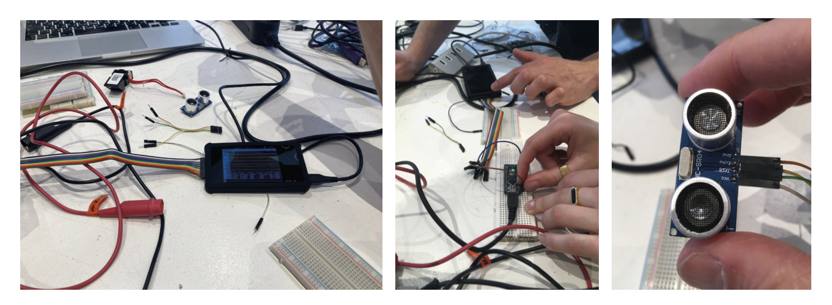
I did the group assignment together with Jonathan, Sander, and Joany.
We probed a distance sensor and read the data both with the Arduino simulator and the interface.
This is the code we used to test the sensor:
const int EchoPin = 7;
const int TriggerPin = 6;
const int LedPin = 4;

void setup() {
Serial.begin(9600);
pinMode(TriggerPin, OUTPUT);
pinMode(EchoPin, INPUT);
pinMode(LedPin, OUTPUT);
}

void loop() {
int cm = ping(TriggerPin, EchoPin);
Serial.println("Measured distance: " + String(cm) + "cm");
delay(100);
}

int ping(int TriggerPin, int EchoPin) {
long duration, distanceCm;

digitalWrite(TriggerPin, LOW);  //to generate a clean pulse we set LOW 4us
delayMicroseconds(4);
digitalWrite(TriggerPin, HIGH);  //we generate Trigger (trigger) of 10us
delayMicroseconds(10);
digitalWrite(TriggerPin, LOW);

duration = pulseIn(EchoPin, HIGH);  //we measure the time between pulses, in microseconds

return distanceCm;
}
Individual Assignment Process 🏊♀️
For the individual assignment, I tested two kind of sensors:
- A distance sensor with the hello-world board;
- A temperature sensor with the Arduino board.
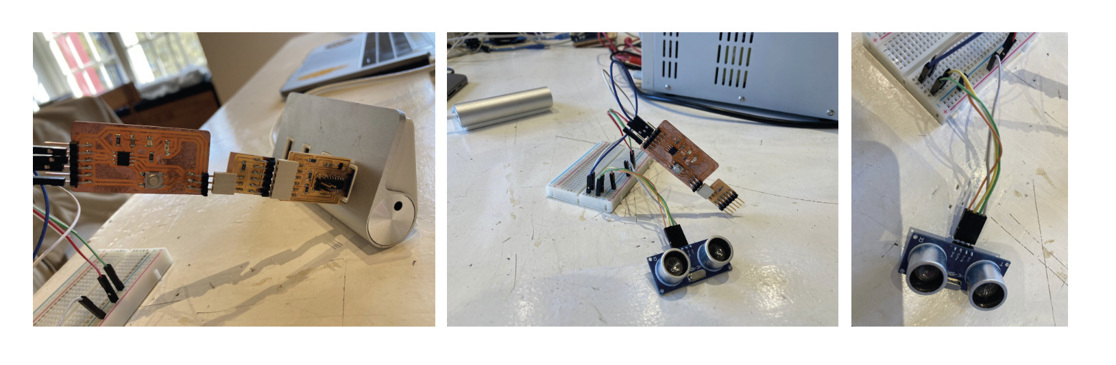
Distance Sensor + Led Blink
I did test the hello world board with a distance sensor. In order to be sure that it was working, I programmed the board that when the sensor detects the hand at 3 cm distance, it makes the led blink.
This is the cose which I used to make the assigment:
const int EchoPin = A6;
const int TriggerPin = A7;
const int LedPin = A1;

void setup() {
Serial.begin(9600);
pinMode(TriggerPin, OUTPUT);
pinMode(EchoPin, INPUT);
pinMode(LedPin, OUTPUT);
}

void loop() {
int cm = ping(TriggerPin, EchoPin);
Serial.println("Measured distance: " + String(cm) + "cm");
delay(100);
}

int ping(int TriggerPin, int EchoPin) {
long duration, distanceCm;

digitalWrite(TriggerPin, LOW);  //to generate a clean pulse we set LOW 4us
delayMicroseconds(4);
digitalWrite(TriggerPin, HIGH);  //we generate Trigger (trigger) of 10us
delayMicroseconds(10);
digitalWrite(TriggerPin, LOW);

duration = pulseIn(EchoPin, HIGH);  //we measure the time between pulses, in microseconds

distanceCm = duration * 10 / 292/ 2;   //we convert distance, in cm
if(distanceCm < 30){
    digitalWrite(LedPin, HIGH);   // turn the LED on (HIGH is the voltage level)
    delay(1000);                       // wait for a second
    digitalWrite(LedPin, LOW);    // turn the LED off by making the voltage LOW
    delay(1000);
}
return distanceCm;
}
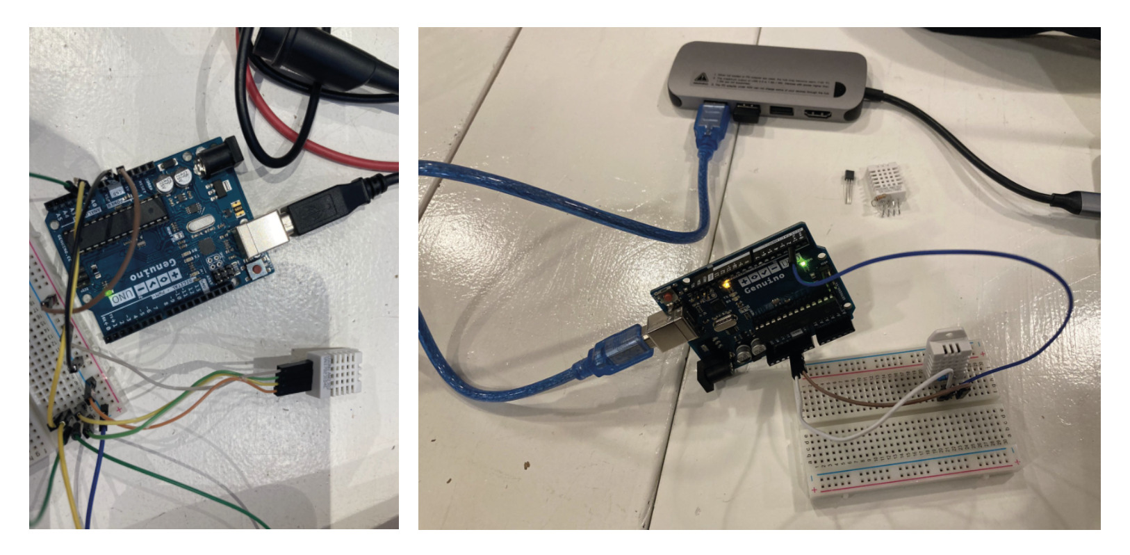
Temperature Sensor
I also tested a temperature sensor which I may use for the development of my final project. I tested it using an Arduino board.
I used this code to check the sensor:
#include "DHT.h"
#define DHTPIN 2
#define DHTTYPE DHT22

DHT dht(DHTPIN, DHTTYPE);

void setup() {
Serial.begin(9600);
Serial.println("DHTxx test!");

dht.begin();
}

void loop() {

delay(2000);
float h = dht.readHumidity();
float t = dht.readTemperature();
float f = dht.readTemperature(true);

if (isnan(h) || isnan(t) || isnan(f)) {
    Serial.println("Failed to read from DHT sensor!");
    return;
}

float hif = dht.computeHeatIndex(f, h);
float hic = dht.computeHeatIndex(t, h, false);

Serial.print("Humidity: ");
Serial.print(h);
Serial.print(" %\t");
Serial.print("Temperature: ");
Serial.print(t);
Serial.print(" *C ");
Serial.print(f);
Serial.print(" *F\t");
Serial.print("Heat index: ");
Serial.print(hic);
Serial.print(" *C ");
Serial.print(hif);
Serial.println(" *F");
}
Retrospective 🤔
This week resulted in being faster that expected. I did not have much trouble when testing the sensors for the individual assignment, which gives me more time to work on my final project.
Final Project 🧘🏼✨🌸
For my final project I will use a heart beats Sensor as an Input. I did tested it using an Arduino Board in first place.
Following the instructions of this website, I seted up the hardware and use the following code to make the sensor work:
//  Variables
int PulseSensorPurplePin = 0;        // Pulse Sensor PURPLE WIRE connected to ANALOG PIN 0
int LED13 = 13;   //  The on-board Arduion LED


int Signal;                // holds the incoming raw data. Signal value can range from 0-1024
int Threshold = 550;            // Determine which Signal to "count as a beat", and which to ingore.


// The SetUp Function:
void setup() {
pinMode(LED13,OUTPUT);         // pin that will blink to your heartbeat!
Serial.begin(9600);         // Set's up Serial Communication at certain speed.

}

// The Main Loop Function
void loop() {

Signal = analogRead(PulseSensorPurplePin);  // Read the PulseSensor's value.
                                            // Assign this value to the "Signal" variable.

Serial.println(Signal);                    // Send the Signal value to Serial Plotter.


if(Signal > Threshold){                          // If the signal is above "550", then "turn-on" Arduino's on-Board LED.
    digitalWrite(LED13,HIGH);
} else {
    digitalWrite(LED13,LOW);                //  Else, the sigal must be below "550", so "turn-off" this LED.
}


delay(10);


}
For the sensor to be much more sensitive, I could play around with the Threshold number. I finally decided to use a more acurated value of 530, in this way the sensor reads the beats faster.
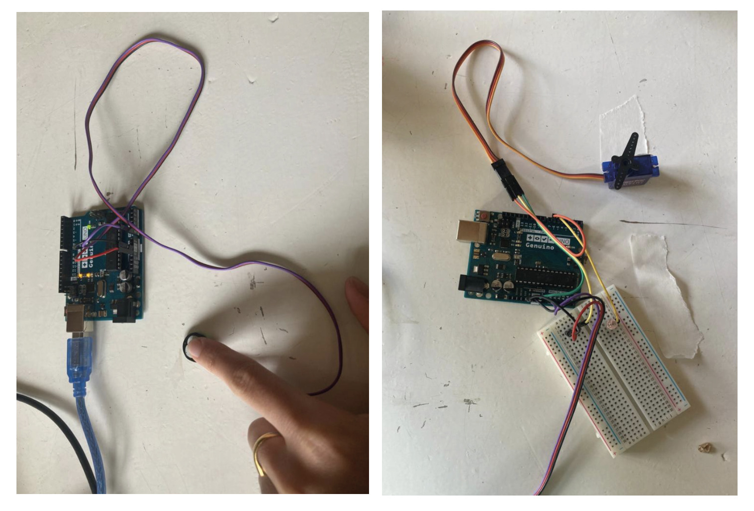
Since I wanted to explore new Output possibilities and use a DC Motor for my final project. I did test this code where a Servo Motor turns on the same rhythm of the heartbeat. In this way, I could test the connection between the heartbeats sensor as an INPUT and a Servo Motor as an OUTPUT in order to translate my beats into the movement of the propellers.
#include <Servo.h>

/*
Every Sketch that uses the PulseSensor Playground must
define USE_ARDUINO_INTERRUPTS before including PulseSensorPlayground.h.
Here, #define USE_ARDUINO_INTERRUPTS true tells the library to use
interrupts to automatically read and process PulseSensor data.

See ProcessEverySample.ino for an example of not using interrupts.
*/
#define USE_ARDUINO_INTERRUPTS true
#include <PulseSensorPlayground.h>

/*
The format of our output.

Set this to PROCESSING_VISUALIZER if you're going to run
    the Processing Visualizer Sketch.
    See https://github.com/WorldFamousElectronics/PulseSensor_Amped_Processing_Visualizer

Set this to SERIAL_PLOTTER if you're going to run
    the Arduino IDE's Serial Plotter.
*/
const int OUTPUT_TYPE = SERIAL_PLOTTER;

/*
Pinout:
    PULSE_INPUT = Analog Input. Connected to the pulse sensor
    purple (signal) wire.
    PULSE_BLINK = digital Output. Connected to an LED (and 220 ohm resistor)
    that will flash on each detected pulse.
    PULSE_FADE = digital Output. PWM pin onnected to an LED (and resistor)
    that will smoothly fade with each pulse.
    NOTE: PULSE_FADE must be a pin that supports PWM. Do not use
    pin 9 or 10, because those pins' PWM interferes with the sample timer.
*/
const int PULSE_INPUT = A0;
const int PULSE_BLINK = 13;    // Pin 13 is the on-board LED
const int PULSE_FADE = 5;
const int THRESHOLD = 540;   // Adjust this number to avoid noise when idle

/*
All the PulseSensor Playground functions.
*/
PulseSensorPlayground pulseSensor;

/*
Make a heart servo, the pin to control it with, and a servo position variable
*/
Servo heart;
const int SERVO_PIN = 6;
int pos = 90;

void setup() {
/*
    Use 115200 baud because that's what the Processing Sketch expects to read,
    and because that speed provides about 11 bytes per millisecond.

    If we used a slower baud rate, we'd likely write bytes faster than
    they can be transmitted, which would mess up the timing
    of readSensor() calls, which would make the pulse measurement
    not work properly.
*/
Serial.begin(115200);
// set up the heart servo on SERVO_PULSE
// set servo position to pos (90 degrees, mid position)
heart.attach(SERVO_PIN);
heart.write(pos);

// Configure the PulseSensor manager.
pulseSensor.analogInput(PULSE_INPUT);
pulseSensor.blinkOnPulse(PULSE_BLINK);
pulseSensor.fadeOnPulse(PULSE_FADE);

pulseSensor.setSerial(Serial);
pulseSensor.setOutputType(OUTPUT_TYPE);
pulseSensor.setThreshold(THRESHOLD);

// Now that everything is ready, start reading the PulseSensor signal.
if (!pulseSensor.begin()) {
    /*
    PulseSensor initialization failed,
    likely because our particular Arduino platform interrupts
    aren't supported yet.

    If your Sketch hangs here, try changing USE_ARDUINO_INTERRUPTS to false.
    which doesn't use interrupts.
    */
    for(;;) {
    // Flash the led to show things didn't work.
    digitalWrite(PULSE_BLINK, LOW);
    delay(50);
    digitalWrite(PULSE_BLINK, HIGH);
    delay(50);
    }
}
}

void loop() {
/*
    Wait a bit.
    We don't output every sample, because our baud rate
    won't support that much I/O.
*/
delay(20);

// write the latest sample to Serial.
pulseSensor.outputSample();

// write the latest analog value to the heart servo
moveServo(pulseSensor.getLatestSample());

/*
    If a beat has happened since we last checked,
    write the per-beat information to Serial.
*/
if (pulseSensor.sawStartOfBeat()) {
    pulseSensor.outputBeat();
}
}

/*
Map the Pulse Sensor Signal to the Servo range
Pulse Sensor = 0 <> 1023
Servo = 0 <> 180
Modify as you see fit!
*/
void moveServo(int value){
pos = map(value,0,1023,0,180);
heart.write(pos);
}
The code perfectly worked with Arduino, but I had to make some changes when using mt hello World Board since the Library’s functions used for the sensor were not always compatible with the microcontroller 1614.
It can be found more info about how I fixed the code and the code itself on my Final Project Page.