Week 10. Output Devices
Before the Start
Introduction 🖊
This week relates to Output Devices.
Fab Assignments 📚
-
Group assignment:
- Measure the power consumption of an output device.
- Document your work to the group work page and reflect on your individual page what you learned.
-
Individual assignment:
- Add an output device to a microcontroller board you’ve designed and program it to do something.
My Goals 🎯
- What I think I already know:
- I have a theoretical knowledge acquired in my bachelor’s related to motors.
- What I want to learn:
- Test different kinds of motors, learning more in deep their specifications, and how to make them work programming with Arduino C+.
Project Management
How I’m going to organize my work during the week.
| Task | Time | Day |
|---|---|---|
| Research | 3h | 9, May |
| Group Assignment | 6h | 30, March |
| Individual Assignment | 5h | 9, May |
| Documentation | 2h | 9 / 10, May |
Research
I am going to use this week to work on the development of my final project. I need a stepper motor to control the pushing mechanism of the bio-extruder upgrade for the 3D printer.
During this week I got a deeper understanding of stepper motors and how they work, in order to properly set up the hardware and code for my final project.
I watched this videos:
- How Stepper Motors Work - Electric motor
- Control Stepper Motor with Arduino - Tutorial
- How To Control a Stepper Motor with A4988 Driver and Arduino
During the Process
Results 🖖
- Add photos or/and videos of the Week’s assignments.
Group Assignment Process 🏊♀️ 🏊🏾 🏊🏽♀️
During the group assignment, Erwin learned us the different Output devices which we could test. Attached some pics of the devices which we tested:
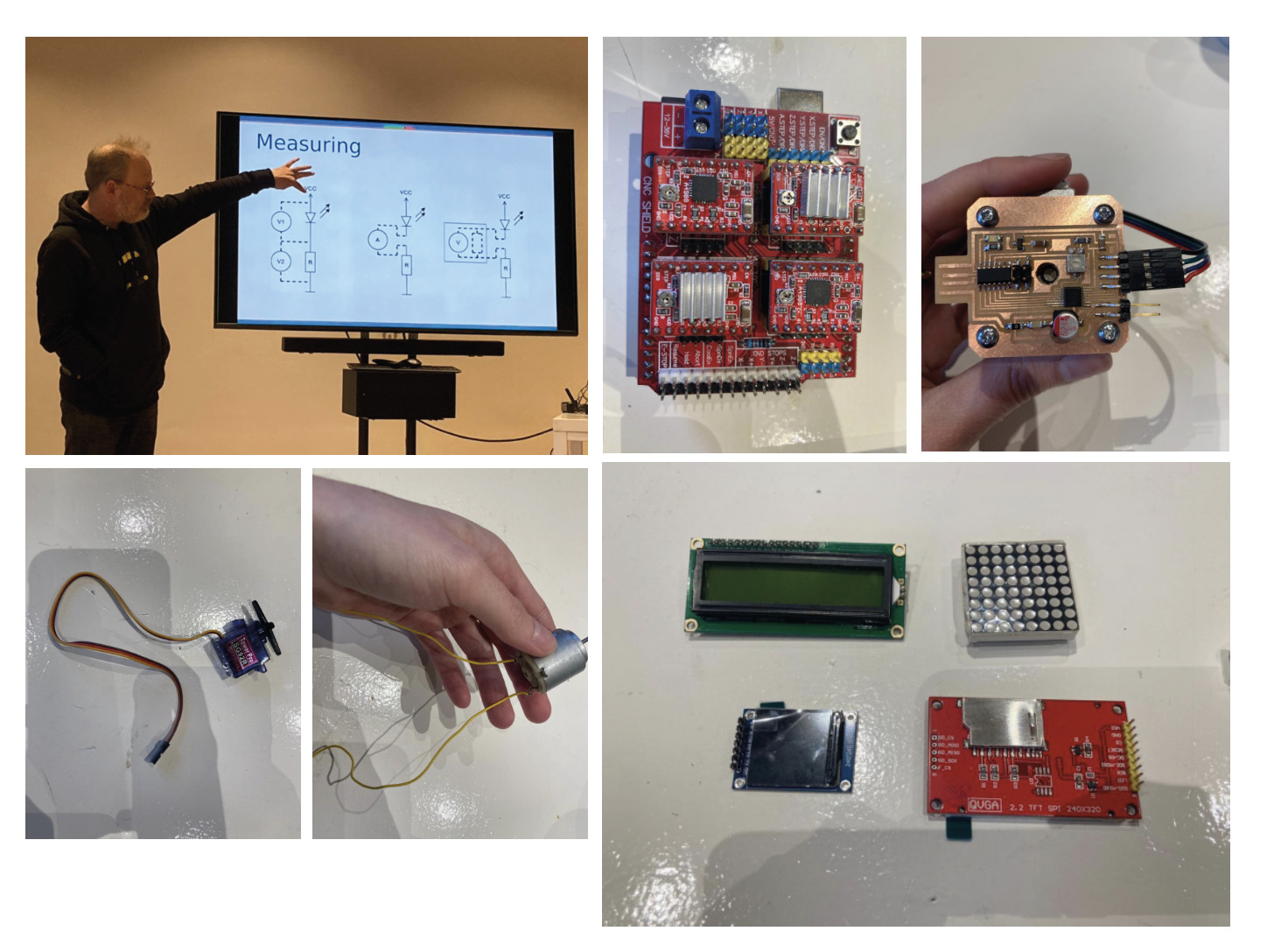
Individual Assignment Process 🏊♀️
Stepper Motor
Stepper Motors are electrical motors that are able to be precisely controlled.
This kind of motor converts electrical energy into mechanical movement. It supplied DC electricity in a controlled sequence to cause movement.
The rotation can be continuous in the forwards or reverse direction, but can also be controlled in small steps for higher precision control. The motor can also stop at a certain moment and stand in that position.
Motor Driver
The motors are connected to motor drivers, which contain electronic switches which are able to turn on and off at high speed.
Controller
The controller determines when the switches are turned on or off.
Arduino boards can be use as controllers, but also our Hello World board :)
ºDegrees x Step
In order to calculate how many degrees x Steps are made, it is possible to use this formula:
-
One rotation = 360 degrees
-
Nº Steps = 200 steps
360 / 200 = 1.8 degrees x step
Components
Outside: - Front end cap - Rear end cap - Main body - Shaft - Electrical connections
Inside: - 2 x Bearing - Rotor: The Shaft and the Rotor rotate together. Is a permanent magnet, which has two halves (North and South Poles). the teeth of each pole are not aligned. - Stator: surrounding the motor. It presents a number of coils of wire which surround the rotor. The driver will control the movement of those wires.
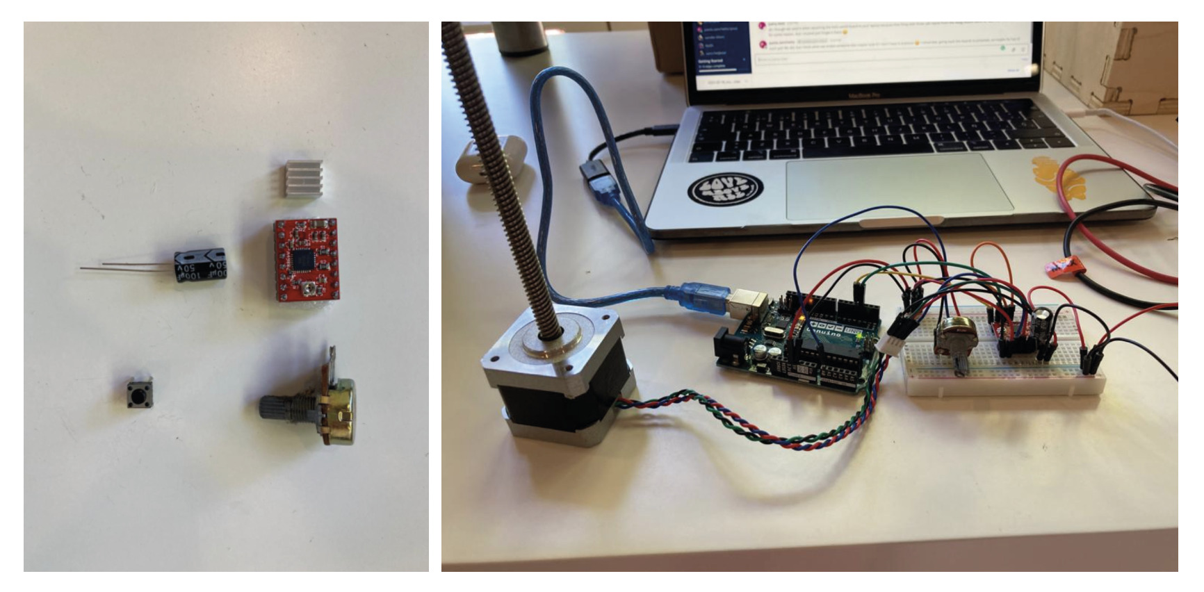
Setting up with Arduino
Attached pictures of the components + set Up which i used to program and test the Stepper motor.
The code used to test the Stepper Motor is the following:
// Stepper Motor Test - Final Project
// a4988 driver
// By Paola Zanchetta

const int stepPin = 3; // Define Pin for Step
const int dirPin = 4; // Define Pin for Direction


void setup() {
    pinMode(stepPin, OUTPUT);
    pinMode(dirPin, OUTPUT);
}

void loop() {
digitalWrite(dirPin,HIGH); // Enables the motor to move in a particular direction
// Makes 200 pulses for making one full cycle rotation
for(int x = 0; x < 200; x++) {
    digitalWrite(stepPin,HIGH);
    delayMicroseconds(500);
    digitalWrite(stepPin,LOW);
    delayMicroseconds(500);
}
delay(1000); // One second delay

digitalWrite(dirPin,LOW); //Changes the rotations direction
// Makes 400 pulses for making two full cycle rotation
for(int x = 0; x < 400; x++) {
    digitalWrite(stepPin,HIGH);
    delayMicroseconds(500);
    digitalWrite(stepPin,LOW);
    delayMicroseconds(500);
}
delay(1000);
}
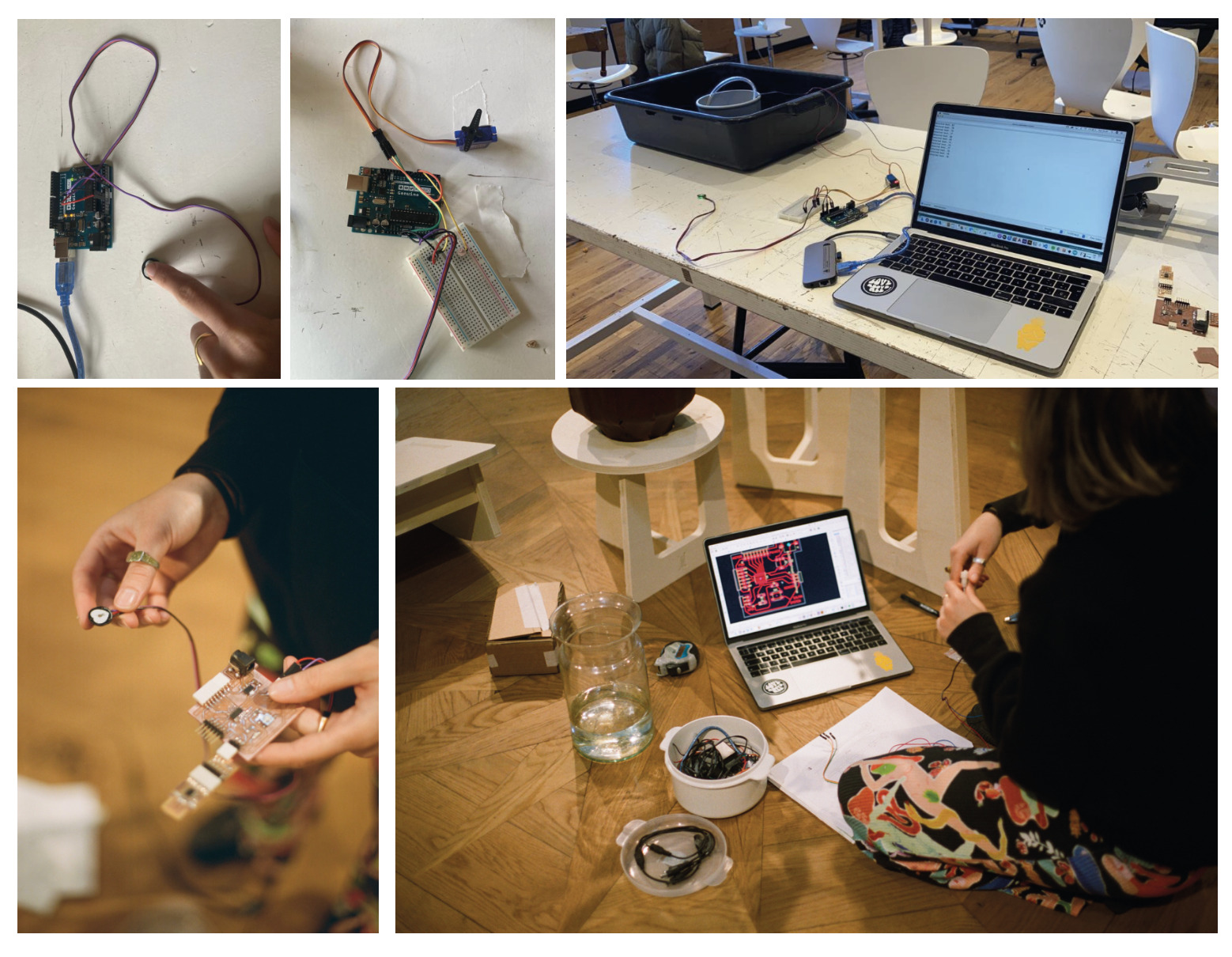
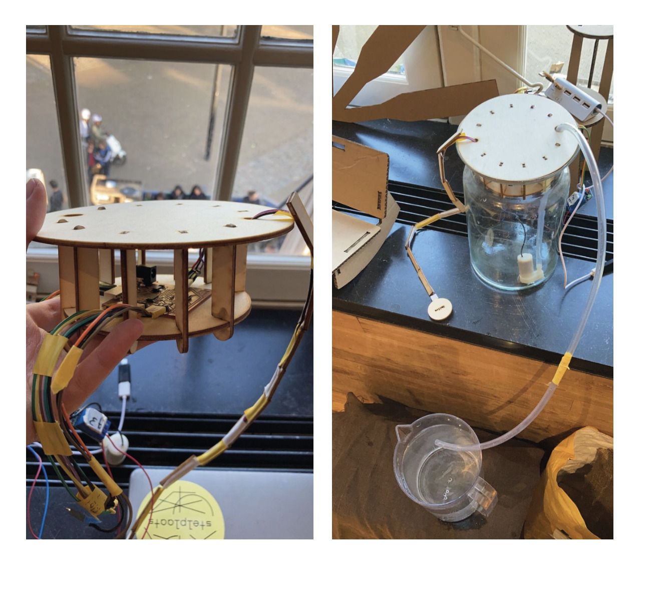
Final Project 🧘🏼✨🌸
Everything which I previously explained, is what I did during the development of FabAcademy’s week 10.
Since I did change the topic of my final project, I had the chance to test other kinds of motors during the following weeks.
I tested using Arduino Servo Motors, DC Motors, and Peristaltic Motors (DC Pump Motor).
Attached are photos of the process + the coding which I used to test the Output devices using both an Arduino Uno Board + my own Hello World board:
The code which I used to work with the Servo Motor and the DC Water Motor are:
Servo Motor + Arduino
// "Saliva" code by Paola Zanchetta - 01/06/2022
// Interactive system human-plants
// In this code the Heart beat sensor shows in the ploter monitor the rate when it is between 60 & 80 BPM's. When the sensor get this beats, the servo motor turns


// Define Servo Libary
#include <Servo.h>
Servo myservo;

// Define Pulse Library
#define USE_ARDUINO_INTERRUPTS true
#include <PulseSensorPlayground.h>

// Define Constants Variants
const int OUTPUT_TYPE = SERIAL_PLOTTER;

const int PULSE_INPUT = A0;
const int PULSE_BLINK = 13;    // Pin 13 is the on-board LED
const int THRESHOLD = 530;   // Adjust this number to avoid noise when idle
int motor = 11;

// Calling the Function
PulseSensorPlayground pulseSensor;

// Define Void SetUp fuction
void setup() {

    Serial.begin(115200);
    myservo.attach(11); // Set Up the servo motor to one location, Library function
    myservo.write(20); // Start = Make one round to see if it is working, Trick from Jonhantan
    delay(1000);      // Wait 1 second
    myservo.write(160); // Stop Start = Make one round to see if it is working, Trick from Jonhantan
    delay(1000);   // Wait 1 second

// Configure the PulseSensor manager.
    pulseSensor.analogInput(PULSE_INPUT);
    pulseSensor.blinkOnPulse(PULSE_BLINK);
    pulseSensor.setSerial(Serial);
    pulseSensor.setOutputType(OUTPUT_TYPE);
    pulseSensor.setThreshold(THRESHOLD);


// Now that everything is ready, start reading the PulseSensor signal
if (!pulseSensor.begin()) {
    for(;;) {
    // Flash the led to show things didn't work.
    digitalWrite(PULSE_BLINK, LOW);
    delay(50);
    digitalWrite(PULSE_BLINK, HIGH);
    delay(50);
    }
}
}

void loop() {

delay(20); // Wait a bit because the baud rate don't support that much I/0

pulseSensor.outputBeat(); // write the latest sample to Serial using = outputBeat()


// If a beat has happened since we last checked, write the per-beat information to Serial

if (pulseSensor.sawStartOfBeat() && pulseSensor.getBeatsPerMinute() > 60 && pulseSensor.getBeatsPerMinute() < 80) { // the Serve Motor turn ON when the heart beat recognizes heart beats between 60 & 80 BPM's
    Serial.println("Detected beat.." + String(pulseSensor.getBeatsPerMinute())); // This line calls the function which returns the latest beats-per-minute. Type = int.
    myservo.write(160); // Turn Servo to 160º position in angles
    delay(1000); // Wait 1 second
    myservo.write(20); // Turns Servo to 20º position in angles
    delay(1000);
}
}
DC Pump Motor + Hello World Board
// "Saliva" code by Paola Zanchetta - 01/06/2022
// Interactive system human-plants
// Heart Beat Sensor + DC Motor Pump

/* Define Pulse Library = FALSE because
the Library is not supported by the Microcontroller */
#define USE_ARDUINO_INTERRUPTS false
#include <PulseSensorPlayground.h>

// Define the format of our output with Arduino
const int OUTPUT_TYPE = SERIAL_PLOTTER;

// Define pinouts
const int PULSE_INPUT = PIN_PA3; // Pulse Sensor
const int PULSE_BLINK = PIN_PA1; // LED Blink
const int THRESHOLD = 550; // Const, limit Threshold

const int RELAY_PIN = PIN_PA4;

byte samplesUntilReport;
const byte SAMPLES_PER_SERIAL_SAMPLE = 10;

// Add Pulse Sensor Library
PulseSensorPlayground pulseSensor;

void setup() {

Serial.begin(115200);

// Configurate motor
pinMode(RELAY_PIN, OUTPUT);
// pinMode(PULSE_INPUT, INPUT);
digitalWrite(RELAY_PIN, HIGH);
delay(100);

// Configure the PulseSensor manager.
pulseSensor.analogInput(PULSE_INPUT);
pulseSensor.blinkOnPulse(PULSE_BLINK);

pulseSensor.setSerial(Serial);
// pulseSensor.setOutputType(OUTPUT_TYPE);
pulseSensor.setThreshold(THRESHOLD);

// Skip the first SAMPLES_PER_SERIAL_SAMPLE in the loop().
samplesUntilReport = SAMPLES_PER_SERIAL_SAMPLE;

}

void loop() {

if (pulseSensor.sawNewSample()) {

    if (--samplesUntilReport == (byte) 0) {
    samplesUntilReport = SAMPLES_PER_SERIAL_SAMPLE;

    // Define Water Pump start when rating 40-60 BPM's
    if (pulseSensor.getBeatsPerMinute() > 40 && pulseSensor.getBeatsPerMinute() < 70) {
        // pulseSensor.outputBeat();
        Serial.println("Detected beat.." + String(pulseSensor.getBeatsPerMinute()));
        digitalWrite(RELAY_PIN, LOW); // turn on pump
        delay(1000);
        digitalWrite(RELAY_PIN, HIGH);  // turn off pump
        delay(1000);
    }
    }
}
}
Retrospective 🤔
@21/06/22
Looking back in time, this week was a challenge, since designing and coding my own PCBs was still pretty new to me.
The electronics world brings infinite possibilities to work with Output and Input devices, which makes it even more powerful and interesting to learn.
Having experienced testing different outputs, made me realize how much I enjoy this field. This is one of the reasons I decided to change the topic of my final project. In this way, I could experiment and learn more from alternative electronic possibilities. And that is exactly what I did!