
Mechanical Design, Machine Design, this week will be a group effort
to learn / to do
Group assignment:
- Design a machine that includes mechanism + actuation + automation
- Build the mechanical parts and operate it manually.
- Document the group project
Individual assignment:
- Document your individual contribution.
the process
TL / DR
This is the summary of our week. Below follows a more detailed description in text.
You can read it also on our group page
thursday
brainstorm
We started with a one hour brainstorm, in which we all shared our ideas for what to make this week. After sharing an talking through the different ideas, we did a quick vote for our personal two favorites. Turned out we all voted the same, and thus Joany’s idea of creating a “Motion Wall” became our goal for this week.
The plan is to use little servomotors (we found about 25 of them lying around, but there are even more in stock) to move a set of tiles in horizontal or vertical direction, thus creating a moving wallpiece. We also want to add a motion sensor, so that the motion wall can react on presence in some kind of way. This is however an extra, a very nice to have. We will focus on creatigng the moving tiles first.
pitch
We pitched the idea to Henk and got the green light. He advised us to use an Arduino Mega to control the servomotors, instead of creating a whole new pcb for that. Since the Arduino can not power that many motors, we will create a shield that has its own power supply to power the motors and provides access to the Arduino pins.
first tests
After the brainstorm we hooked up some servomotors and started playing. Servomotors have their own driver so they are easy to hook up: just ground and 5V, and a signal wire to control the motion. Soon the table came alive with little servo’s crawling around.
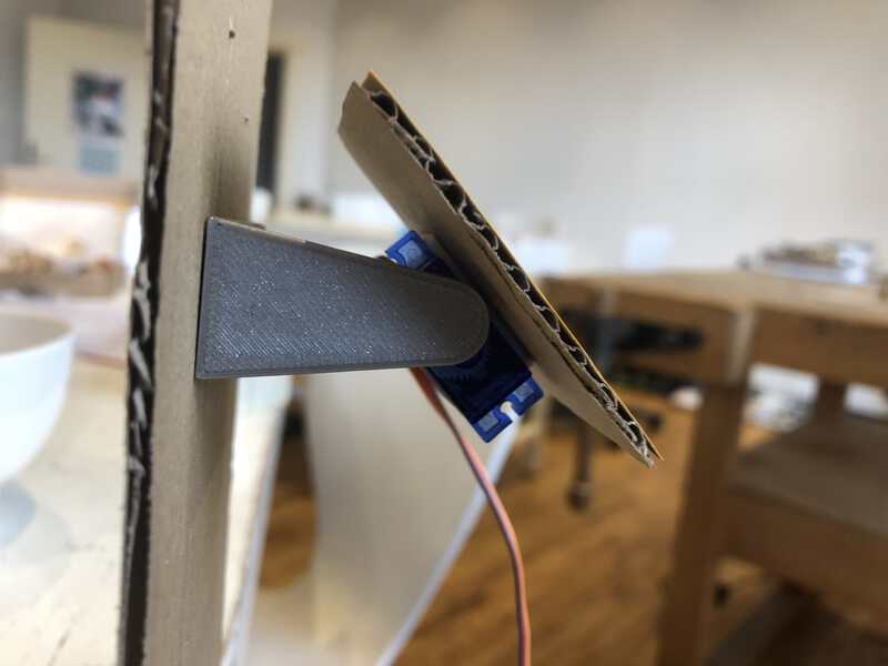
We wanted to test whether to mount the servomotors with the spindle in front, thus creating motion that is parallel to the backplate. Or with the spindle sideways, creating motion that is perpendicular to the backplate. We made a working version of both, with at least one motor.
The parallel motion was easier to manufacture, but the perpendicular motion looked more interesting. Ben 3D printed a little arm to connect to the servo spindle, to connect the tile in the right angle. This quickly revealed a problem: the arm had to be fairly long, and that resulted in a tile that moved in an up/down motion instead of rotation around its centerpoint.
A moment of serendipity gave a solution: mounting the spindle to the baseplate and attaching the tile to the servomotor gave a much better motion.
monday
Monday we started with a short meeting to talk through the plans for the day. This day we aimed to make a proof of concept with 6 motors with their stands, mounted on a backplate, ideally with a sensor attached.
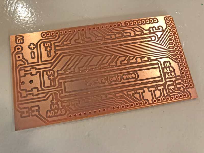
Ben had finalised the 3D brackets during the weekend, and also made a KiCad desifn for the Arduino motor shield. Since he was in another country, I took up the task to mill and stuff the shield, while Jonathan tested out different motion and proximity sensors and Joany focussed on designing the backplate and 3D printing the brackets.
milling
Henk got me a PCB blank that measured 100mmx70mm. Almost enough for the PCB that Ben designed, but not quite: that measured 101mm in length. The right part of the design would fall off. This was not a big problem, since that was only a part used for silkscreen pin numbers in the standard Arduino shield template that Ben had used. I positioned the millbit exactly at the edge of the board and was almost ready to mill when I noticed that Mods had calculated a length of 105mm. Ben’s design had a margin of 2mm on all sides. I contemplated just cutting the .png’s with smaller margins, but came with Joany to the conclusion that it was probably just as good to position the millbit a little bit to the left from the board. So that is what I did. After checking and doublechecking (the broken millbits from the last week fresh in memory) I started the trace job. It took 45 minutes, but no bit was broken.
The next job was to mill the holes for the male pinheaders that would connect the shield to the Arduino Mega. I changed the bit to the 1mm and used the same settings as for the outline. Holes were milled. Then came the outline. Because the millbit would travel in and out of the PCB blank (since the outline of the board was bigger than the blank) I set the speed to 2 and started the job.
This also finished without problems or broken bits.
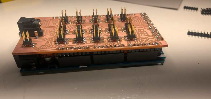
After milling came the stuffing of 15 2x3 headers, 2 2x2 headers and a barrel jack. Oh, and ofcourse a lot of male header pins to connect to the Arduino Mega. For this I pressed the pins into the Arduino sockets and placed the PCB board over them. Everything fit nicely altough there was maybe a little bit too much space between pin and hole. So I had to be very generous with solder.
We did not finish the proof of concept, but I was happy with our progress for the day.
tuesday
Tuesday we started with the 10:30 meeting. Since we did not finish the proof of concept yesterday, it became the goal for this day. We also wanted to research a bit more into the different sensors and possible animations for the tiles.
prototype
We started two 3D print jobs for some extra servo motor brackets and together with Joany I proceeded to mount the motors on the backplate. We noticed that the wires to the motors were long enough for a board of 6 motors, but not long enough when the board became bigger. After some discussion within the group we decided to buy dupont male to female wires to extend the wires.
I started to connect the servo motors to the brackets and noticed that the ones that were printed on the Ultimaker seemed to fit less that the ones that were made on the Prusa. I had to cut quite a bit away with a sharp knife to make the connections fit. To make sure the motors would not fall off I glued them to the brackets.
Then I attached the brackets to the baseplate, guided the wire connectors through the holes that Joany had made and pressed them on the pinheaders on the servo shield. First I tested them with USB power from my computer, and as expected this worked. But we knew that adding more motors would ask more current than the USB connection would provide, and this is where the servo shield came in.
But first I had to connect the shield to a power supply. I used a DC powerbench for this, that I set to 5V. On Henk’s advice I made a cable that at one end had a power connector/barrel plug and on the other end two pins. The plug went in the barrel jack on the board, and the plugs I connected with alligator clips to the power supply.
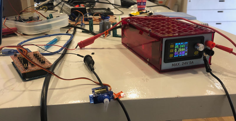 power supply to the right, in the middle the aligator clips connected to the pins
And then the moment came. Would it work??
It did :-)
All 6 motors rotated with full power. I started to test with more motors. For this I used a test program that Jonathan wrote, that moved each motor one by one. We noticed two things:
- not all motors worked
- some motors would come loose from the brackets because of the excessive rotating
- these 6 motors alone uses 1.4A at some point
The first problem I figured was because of bad soldered connections. So I checked every connector. I found 3 connectors that did not work, and those I soldered/reflowed again. This fixed the problem.
For the second problem we wanted to test if Super Glue would fix it.
wednesday
We started the day with our usual morning meeting. We discussed the progress of the day before and the plans for the current day. Now that we had a rig with 6 motors working, I thought it was a good idea to try and test with all motors. We also still had to 3D print brackets and there was the thing with glueing the little white rotors to the brackets.
And ofcourse, there was the design for the tiles and backplate. We had a made some earlier tests with square tiles, but Jonathan was curious as to how hexagonal tiles would work. This was something that we also wanted to try out today.
Joany started to work on the hexagonal backplate and tiles design, while Jonathan tested his Wave code that he had written the day before. Ben was abroad, and had taken on an advisory role.
testing many motors
Based on the tests of the day Ben had calculated that the motors would probably need more than 5A to function together. So my first step was to ask Henk for a bigger powersupply. From now on we tested with a supply to could provide max 15A, although Henk had set it to max 7A to protect the servomotors (and probably us as well).
Connecting all the motors resulted in a big nest of wires and motors that made a little bit of a marching humming sound. We could see that these motors together needed about 2.5A. Jonathan started to label them all, so we could see which one was connected to which pin and he could test and debug his code easier.
I started to glue the white motor connectors into the 3D printed brackets. Because the green Ultimaker brackets were somehow smaller, I had to tune both parts a lot, but eventually got both parts to fit.
Joany meanwhile had finished a test for the hexagonal tiles, that looked very nice, like a flower. Together with Jonathan she attached 7 of the motors and 7 hexagonal tiles, and then came the moment to test.
Very promising :-)
Jonathan determined that two of the servo motors on the plate were spinning 360 degrees. This is not how they are supposed to work, as they should rotate 180 degrees, so we took them out. After some extra testing with the rest of the motors he found two of them not working at all. We doublechecked, and tossed them away. He was then left with one motor without a label at all. This was my mistake, as I had sent him the wrong pin array to test with. It had one pin taken out.
Now all motors were functioning, but there was still a problem in the software, as somehow we could never get all the leftover motors (26) to work all one by one. In a program that used an array with all motors and spinned them one by one, only 24 worked. Then there was a long pause and then it started at the first motor again. If I shuffled the array, it would always be the last two in the array that would not spin. Although it looked like the program did send the spin signal, as there was a pause before the list started at one.
thursday
During the morning meeting we decided that we all liked the hexagonal shapes. We also did some planning. The global plan was to have everything ready for assembling on tuesday the next week. Because of holidays and different schedules the first day that most of us would be at Waag. However, Ben pointed out that we also had to make a video. Making a video and assembling was too much for one day. And so we decided that the best day to assemble way today.
assembling starts
That meant we had to have the design ready to be lasercut. Unfortunately Joany, who had been doing the designs, was not available today and she also had no access to her files. After a bit of going back and forth, Ben made a backplate design, that Jonathan tested out with cardboard. Meanwhile, I 3D printed the last brackets, and glued them.
There was also still the problem of the amount of motors we could control. We had pins for 30, but the software somehow would allow only 24. In the morning meeting, we had decided to just stick with 24 and make a design for that.
But when I tested another script that I found online, I noticed that all connected motors were suddenly working. I got maybe a bit too enthousiast about that, and decided to then go for as many motors as we could. Not thinking of the fact that Jonathan had written a working ‘wave’ animation for the tiles that would work with 24 motors. As we had decided already in the morning meeting. In the end, Ben made a design for 27 motors, meaning the software had to be rewritten. Not a smart move.
The cardboard test that Jonathan made worked, but the holes to screw the brackets on the plate were a bit too big. Ben had made the design in OpenScad, so that was easy to change. I proceeded to cut the backplate from 5mm wood and started assembling the brackets, the motors and do the wiring. At this point I was kind of hurried, as it was about 4 o’clock in the afternoon and I wanted it to be ready before I left.
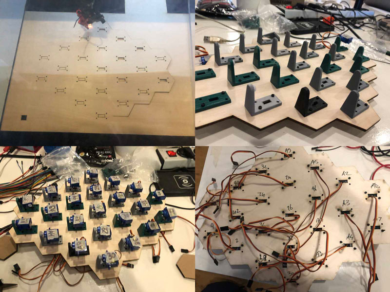 assembling the final backplate and brackets
It took me about 2,5 hours to assemble everything. I connected all the cables, ran the software, it worked!
Good enough to leave it for the weekend. Only then did I reaslise that the total plate was kind of small. About 35cm on the longest side. Not the 150cm thing that we had in mind. Somewhere in the hurry, we had scaled down. And even though it would have been easy to scale up the OpenScad design from Ben, I did not think of it. And now the brackets were all screwed to the plate, so to redo it it would take even more than 2,5 hours. The bright side was that we did not have to extend the cables. But still. Over chat we decided to go along with this for now. Who knows, when there is still time tuesday, we can redo that part again.
tuesday
the making of
In the morning meeting, we made a list with the priorities for today:
- video ✓
- fix two missing servo’s ✓
- lasercut and assemble pixels ✓
- fix the wave animation ✓
- lasercut and assemble casing ✓
- add a sensor
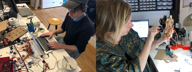
I spent the day creating the Making Of video, while Joany and Jonathan did the final assembly of the MotionWall. Ben helped from remote with the wave code.
wednesday
- add a sensor ✓
Presentation day! Although we were all happy with the final result, there was still a not functional sensor. With about an hour left on the clock, I combined the code Jonathan wrote for the sensor with the code Ben wrote for the motorwave. With some last minute debugging together with Jonathan we got the sensor to work. Only when the laptop is connected to the Arduino though. Still a mystery to be solved.
This is our final result, the wave starts because I waved at it and stops when I am too long out of vision.
wrapping it up
my contribution to the project
I think my main contribution to the project was getting a lot of work done. Based on Ben’s design of the breakout PCB board I milled, stuffed and tested it. I connected all the motors to the board to test both the connections on the board and the servo motors. I 3D printed countless of brackets and hand glued all the servo motors to it. I attached all the brackets to the base plate with tiny screws. On the last day I made the making-of video.
room for improvement
There is always room for improvement. Things we liked to develop further:
- create a better wavelike animation
- add light inside the casing so there is also a play with light when the hexagons move
- make it bigger
- make the casing a bit more shallow