This week we will be programming the Hello World board that we made two weeks ago
to learn / to do
Group assignment:
- Compare the performance and development workflows for other architectures
- Document your work to the group work page and reflect on your individual page what you learned
Individual assignment:
- Read the datasheet for your microcontroller
- Use your programmer to program your board to do something
looking ahead
what I already know
This week I will be on known grounds. I have been programming for about 30 years now, in different languages. Not really in C though. I have used the Arduino environment when playing a bit around with Arduino boards. I understand the setup() and loop() concepts, and also know my way around the “arduino” language. I do not like the Arduine IDE, I think it is a poor excuse for developers editor.
what I want to learn
I want to learn to program the microcontroller! And also, I want to finally understand how all these PCB boards I have been making go together.
the process
reading the datasheet
My hello world board has an AtTiny412
By glancing over the table of contents I get a good idea of the capabilities of this controller.
The general pinout is explained here: https://ww1.microchip.com/downloads/en/DeviceDoc/40001911A.pdf#page=13
Here I can see that this microcontroller has 8 pins. Pin 1 and 8 are reserved for VCC and GND. 5 of the pins (2,3,4,5,7) have both digital and analog functionality. Pin 6 is the UPDI pin that you can use to pogram it, pin 7 has also clock functionality.
On page 14 I can see some more details for the pins: http://ww1.microchip.com/downloads/en/DeviceDoc/40001911A.pdf#page=14
Here I learn that pin 4 and 5 can be used for serial communication (TX/RX), but also for I2C (SDA,SCL)
On page 15 I learn about the memory of the AtTiny412: https://ww1.microchip.com/downloads/en/DeviceDoc/40001911A.pdf#page=15
4Kb of flash memory 256b SRAM 128B EEPROM
Flash memory is the memory that holds your program, so this size is important. EEPROM is erasable program memory, values you store here will stay even when you turn off power. Useful for example for a chip with an ID, or specific parameters. SRAM is working memory.
programming
In short notes for now, until I have time to write a better report.
- I checked the LED with the multimeter: yes
- I checked with the multimeter if the LED got a pulse from the controler: no
It turned out that I was using the wrong designator for the pin that the LED was connected to. *I used the designator in the red box (4), but should have used the one in the green box: A1

the different boards
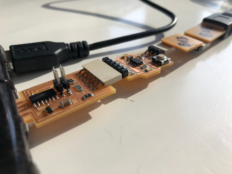
My Hello World board has two headers:
- A 3 pin header that connects to UPDI. UPDI is the interface that I use to program my board. It connects to the UPDI pin in my controller. And it connects to the UPDI pin in the programmer board.
- A 6 pin header that connects to the FTDI. The FTDI is the board that converts the serial communication from my board to the USB controller in my laptop. I use this to test my board, I can see its serial output with this interface. Also, it provides power for my board.
The little converter board with both a 3 pin header and a 6 pin header is used to connect the UPDI of my board to the UPDI of the programmer.
I have made two FTDI programmers, one with the SAMD chip and the other with the FT230x. Since I have both programmers, I was able to connect both sides of my Hello world board to USB, making testing a lot easier. I picked up this idea from Ben

Simon Says
I want to make a Simon Says game with the LED light and the BUTTON. The idea is as follows: the board plays a sequence of long and short lights. You have to repeat this sequence with the button. The board than plays the sequence again, but longer. As long as you keep repeating correctly, the board will keep replying with a longer sequence.
programming
I use the Arduino environment to code and upload the sketches but I do not really like it, so I also try if I can use my editor of choice VSCode. Arduino just produces text files, and it is no problem to edit them with another editor like VSCode. However, to upload I still have to go back to Arduino. But after I download a Arduino for VSCode plugin, VSCode handles this quite nicely. It even has a Serial Monitor.

Squeezing out bytes
String sequence = “01010010110101010001”;
Sketch uses 4043 bytes (98%) of program storage space. Maximum is 4096 bytes.
Global variables use 100 bytes (39%) of dynamic memory, leaving 156 bytes for local variables. Maximum is 256 bytes.
char sequence[] = “01010010110101010001”;
Sketch uses 2695 bytes (65%) of program storage space. Maximum is 4096 bytes.
Global variables use 83 bytes (32%) of dynamic memory, leaving 173 bytes for local variables. Maximum is 256 bytes.
turned off Serial
Sketch uses 1363 bytes (33%) of program storage space. Maximum is 4096 bytes.
Global variables use 30 bytes (11%) of dynamic memory, leaving 226 bytes for local variables. Maximum is 256 bytes.
Demo
Final Code
You can view all the code here
