to learn / to do
Group assignment:
- Test the design rules for your 3D printer(s)
- Document your work and explain what are the limits of your printer(s) (in a group or individually)
- Document your work to the group work page and reflect on your individual page what you learned
Individual assignment:
- Design and 3D print an object (small, few cm3, limited by printer time) that could not be easily made subtractively
- 3D scan an object, try to prepare it for printing (and optionally print it)
looking ahead
what I already know
Again, something very new to me this week. Ofcourse I have heard about 3D printing, but I have never done this. The same goes for 3D scanning.
what I want to learn
Well, 3D printing sounds more interesting than 3D scanning. There are four 3D printers at Waag, and I like to try them all, but half of them is also good. Also, I want to learn to document a bit more concise, as it still takes me a lot of time.
3D printing
the printers
At Waag we have 4 3D printers:
- Prusa i3 MK3
- Ultimaker 2
- Ender Creality
- a resin printer that we did not use.
The first 3 are variations of the same printertype: one that uses filament and a heated nozzle to extrude the material on to a plate. Also commonly known as FDM printers.
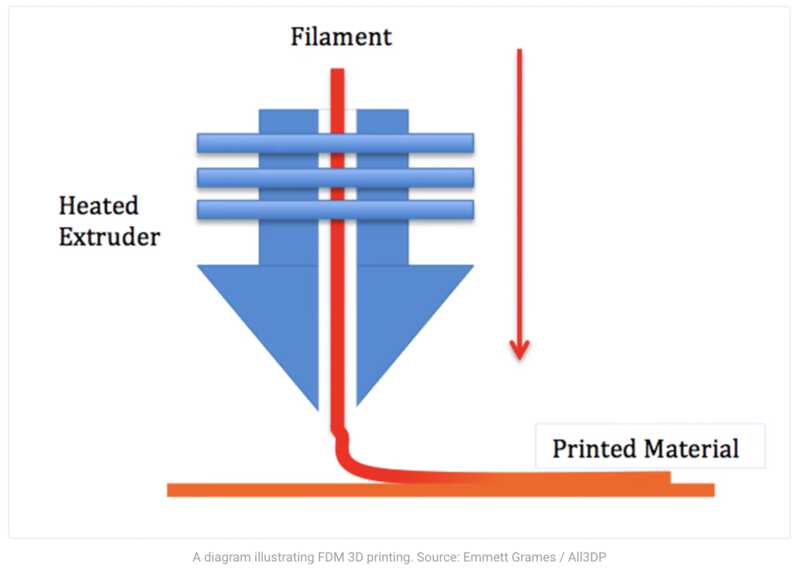
The filament is the material. It melts in the nozzle and comes out of it as a molten string. When everything is done right (the filament is the right temperature and quality, the nozzle is clean and heated properly, the base is clean and also heated) the filament drops on to the base and sticks there. New lines of filament stick to that, and so builds up the 3D print.
The printers all have a printhead that moves in the x/y planes and a printbase that moves in the z-plane. By contantly lowering the base, the material will build upon the earlier layers and form the 3D print. This three-axis way of printing is called Cartesian printing.
All 3 printers have a heated base, so that the filament will stick to it and stay warm enough to build on. This base is around 60 degrees celcius.
The Ultimaker uses a different diameter of filament: 2,85 mm vs 1.75mm for Prusa and Ender
All 3 printers have a 0.4mm nozzle, this is more or less the standard size.
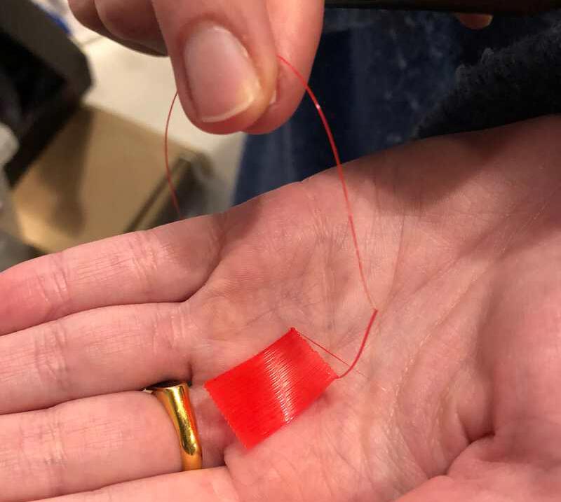
filament
There are lots of materials for the filament, they are all made from a form of plastic. We use PLA, because it has the name to be biodegradable. Its base is corn / cornstarch, and thus a renewable material, not a fossil material. On the other hand, its base is also a food, and for 1KG PLA, 2.65KG corn is required. Its biogradability is guaranteed under certain circumstances (like a temperature above 55 degrees celsius) and does not mean that the material is also compostable. After all, it is a polymer that takes at least about 80 years to compose in the wild.
PLA attracts moist, which causes it to degrade over time. Not enough to disappear all by itself, but certainly enough to have a unwanted impact on its printing capabilities. That is why PLA is best stored in a plastic bag in a dark closet. If it had gotten too moist for printing, it is possible to restore it by heating it in an oven for a few hours on 55 degrees celcius.
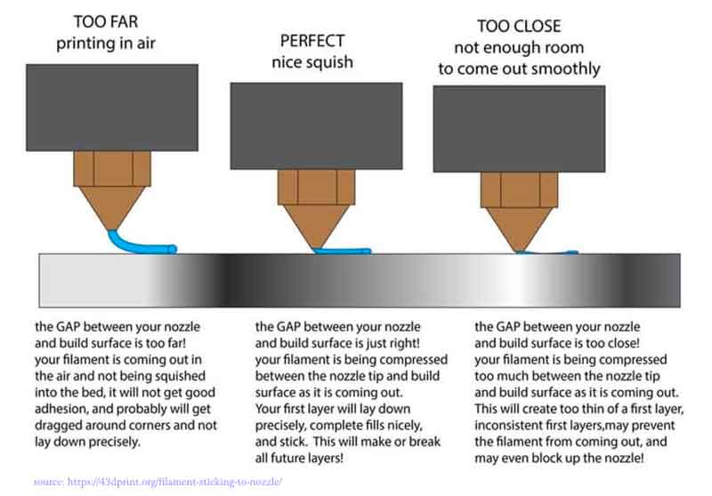
calibration
Before printing for the first time, and also every now and then, the printerbed needs to be calibrated. This means that it will be made level with the nozzle, and also that the distance between the nozzle and the bed will be set to the right distance.
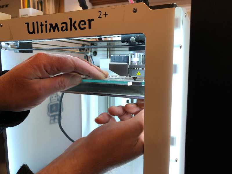
The Prusa has an auto levelling feature. The Ultimaker and Ender do not. These need to be calibrated by hand, by following some steps that the printers guide you through.
To calibrate the nozzle distance the Prusa has an option to draw a testing line of filament while giving you the possibility to change the height of the nozzle in very tiny steps. The testing line ends in creating a little mat of filament that gives you a good indication of the results of your calibration.
For the Ultimaker and Ender you are advised to use a piece of paper to measure the correct distance between nozzle and filament.
group assignment
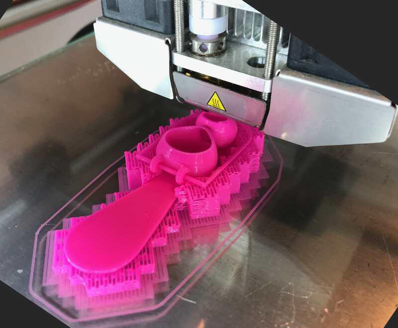
The group assignment for this week was to test the design rules for your 3D printer(s). We divided in three groups for this, a group for every printer. I initially went to work with Bas and Benjamin with the Ender, but the Ender appeared to be broken and had to be serviced first. A task that Bas and Benjamin were more than ready for it seemed. Since 3D printing is new to me, this was a bit too much for me and I switched to a group with Saco and Jonathan, who were working with the Ultimaker.
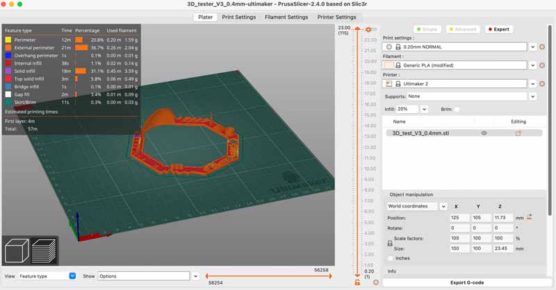
We downloaded a 3D printer test, and I downloaded PrusaSlicer. PrusaSlicer is software made by Prusa that generates the g-code for your 3D printer. It has a very good interface, where you can rotate and scale your 3D model, and it has profiles for almost all 3D printers on the market. In fact it is a bit like the “print dialogs” in software like Word that you use to send your document to the printer. But with a lot more options and intelligence. Apart from selecting the type of filament, printer and print quality, it also shows you how your model will be printed layer by layer and it can add things like infills (filling up hollow areas to prevent collapsing) and supports (supporting parts of your model that would otherwise be printed in mid-air).
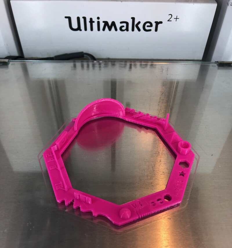
I prepared the model in Prusaslicer, exported the g-code onto the SD card and off we went to the Ultimaker.
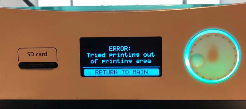
First we calibrated and levelled the Ultimaker. When we loaded the model we were greeted with an error message: “ERROR. Tried printing out of printing area”. I checked the PrusaSlicer settings again and I realised I exported the model for the Prusa instead of the Ultimaker.
After correcting that, the printer was ready to print our model.
The first print did not go well. It turned out that we did not calibrate the nozzle distance correctly and the nozzle was too close to the surface. Jonathan corrected this, and we started the printer again. Now it went well, and after a good 10 minutes we had our test model.
Prusa and Ultimaker compared
Below are photos of the test models from the Ultimaker (pink) and the Prusa (red) side by side. There are certainly differences in print quality, I circled them with black. Overall, the quality of the Prusa is better. This may be because we had the temperatuer of the nozzle a bit too high.
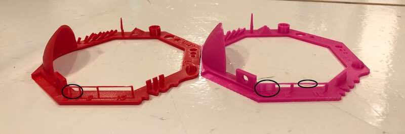 The two frames on the left are open on the Prusa and filled on the Ultimaker
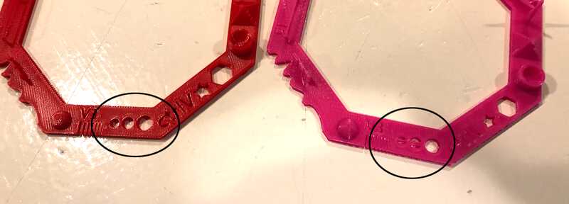 The two holes on the left are open on the Prusa and on the Ultimaker they show some stringing
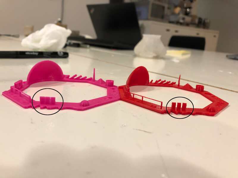 The three tabs are divided on the Prusa, but connected on the Ultimaker
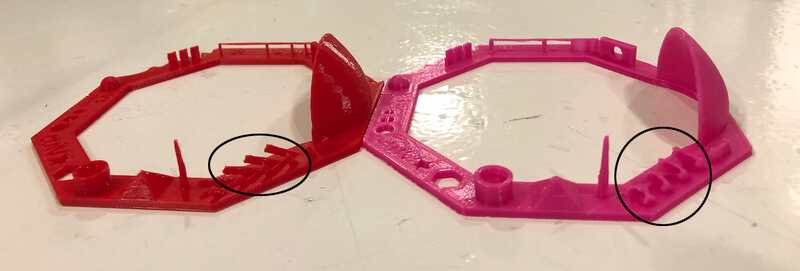 The angled tabs have more overhang on the Prusa
the process
Design and 3D print an object
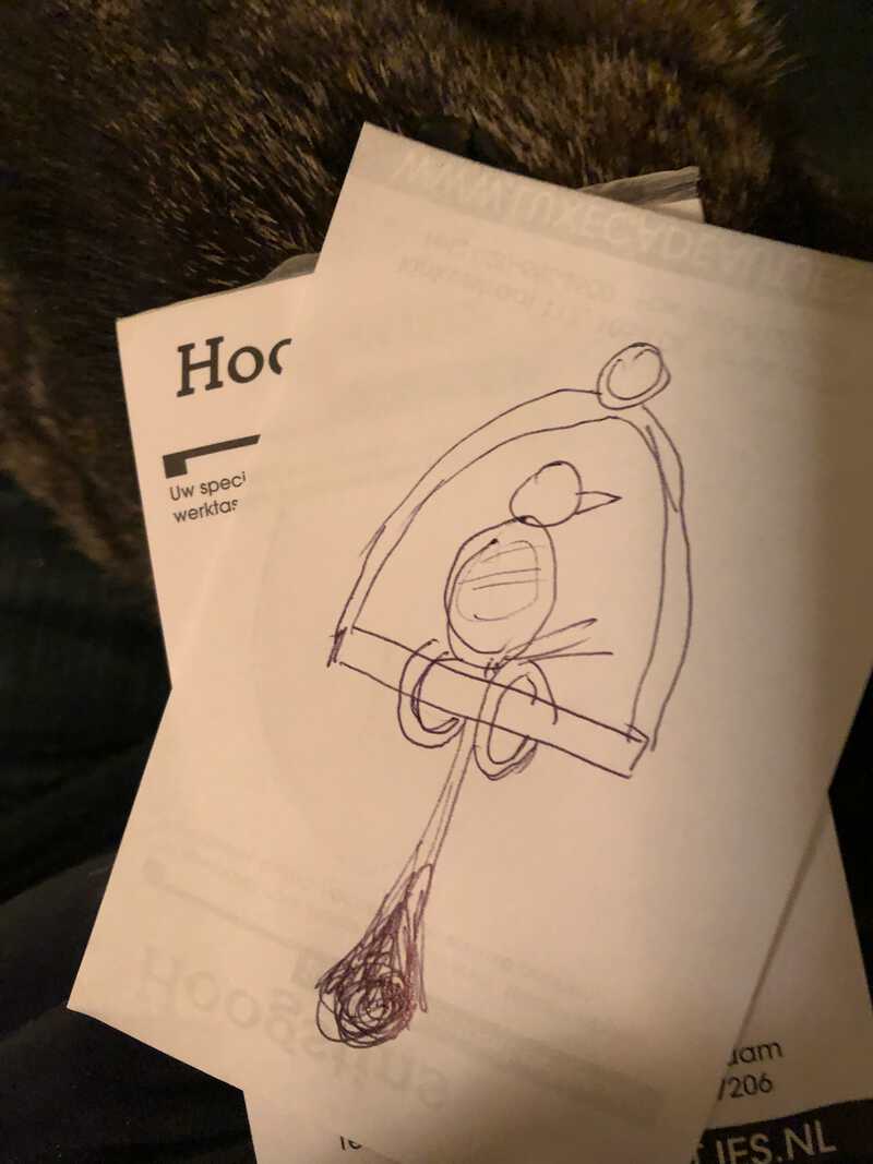
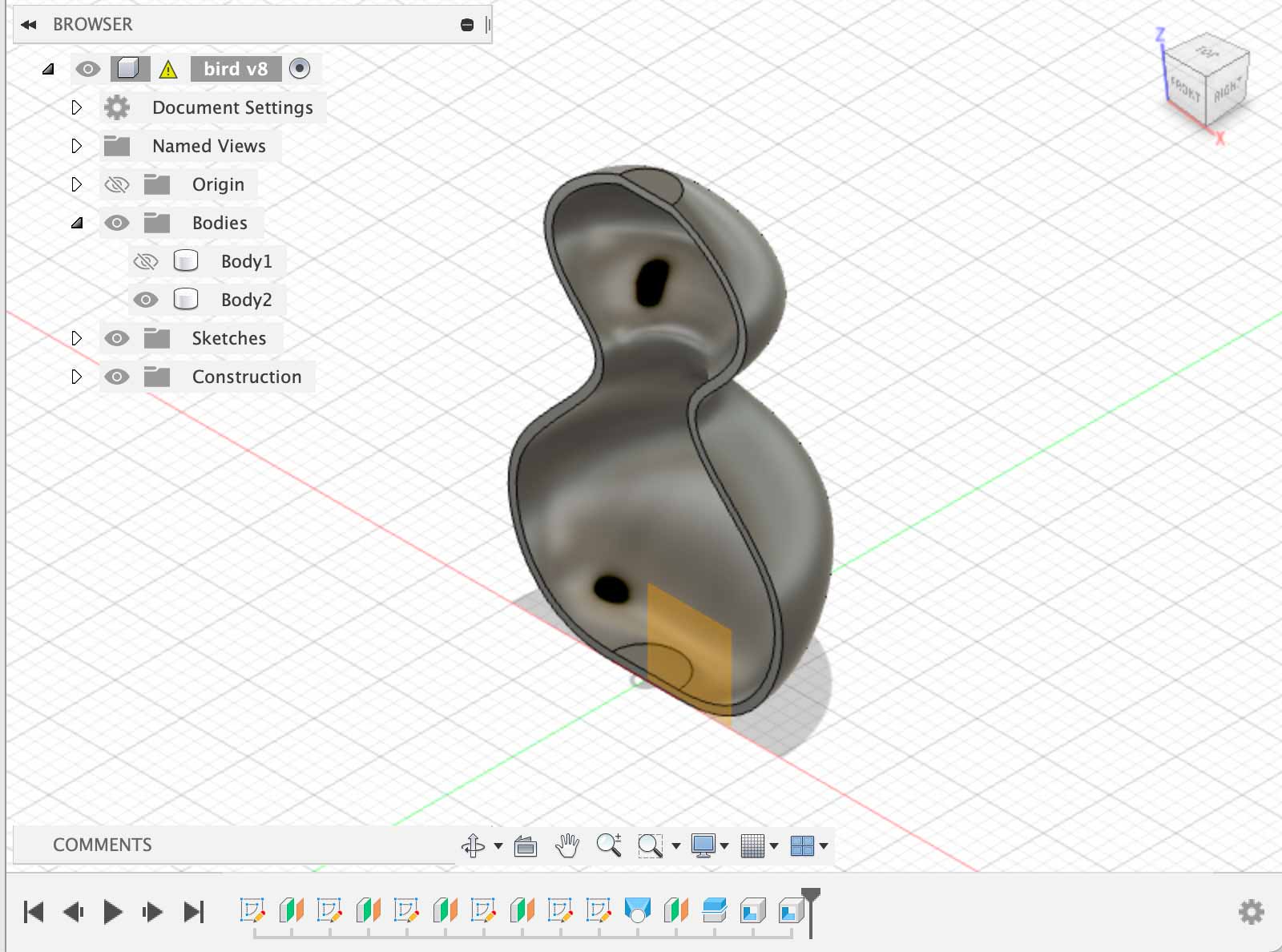
For the individual assignment, I wanted to design and print a bird on a sitting stick. The idea is that the bird can rotate around the stick. The tail has to be heavier than the body for this, so I want the body to be hollow, and the tail to be solid.
This design is not easy to make subtractively, because of the stick that goes through the feet of the bird.
For designing the model I wanted to use Fusion360. Still not too sure about my competence with it, and also not too sure about 3D printing, my goal was to create and print a simple test on friday. If that went well, I would design the rest and print that on monday.
simple bird shape
For the first test, I designed the bird body, in Fusion360. Now my tutorial binging from three weeks ago proved its use, as I recalled and was able to apply many concepts from that week. First up: guided loft and offset planes.
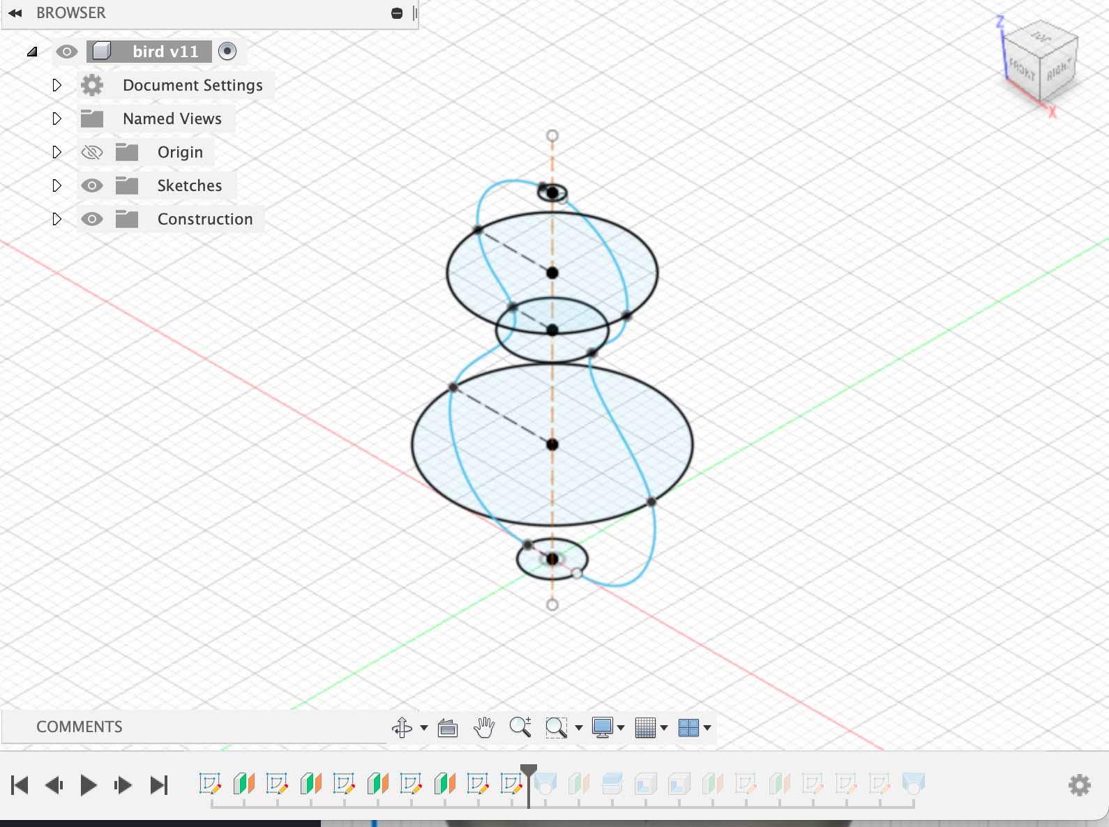
I also learned some new tricks, like dividing a body in half by using a plane, and shelling both halves. I wanted the body of the bird to be hollow, so it would be lighter than the tail.
I also added a little beak, exported the design to .stl and loaded this into PrusaSlicer. First, it appeared that I shelled the model too much, and PrusaSlicer compplained:
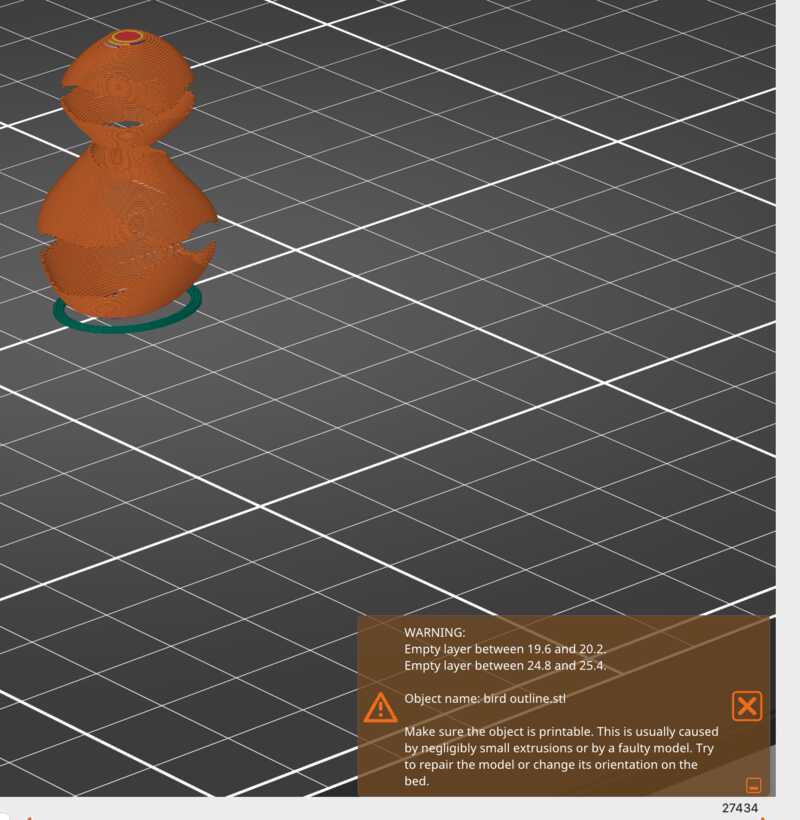
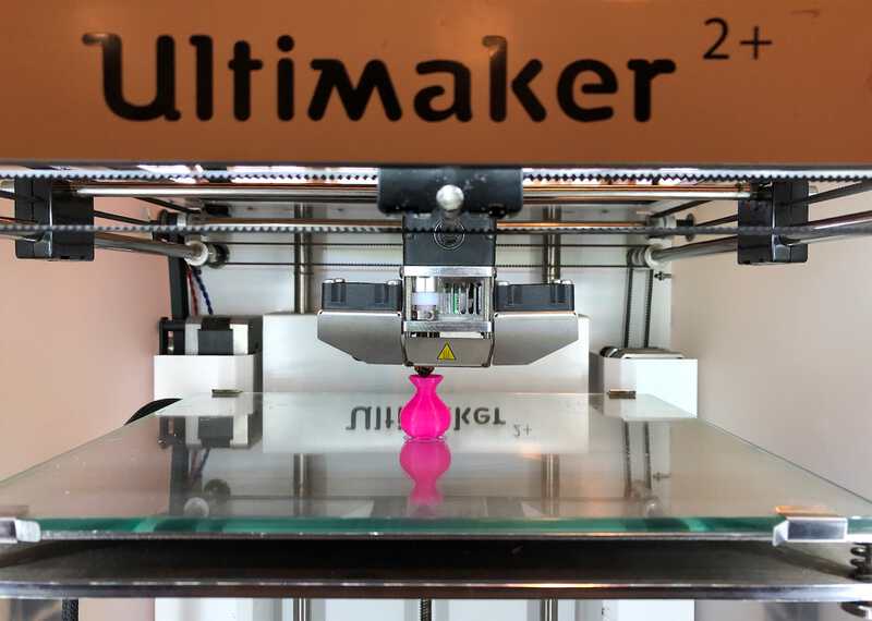
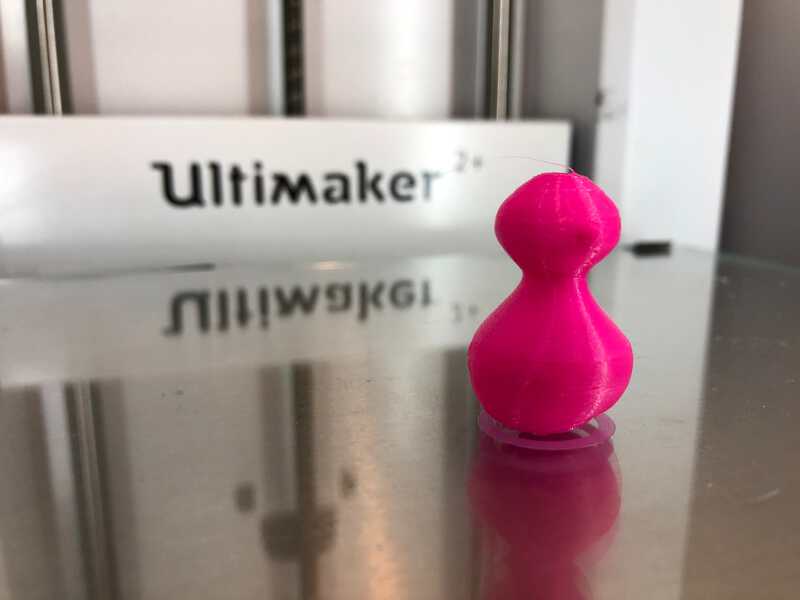
I went back to Fusion360 and made sure the walls of the body were a bit thicker. This time PrusaSlicer was happy. I exported to g-code, loaded the model in the Ultimaker and started the print. This went without problems, and after a good 15 minutes I had a little 3D bird on the plate:
Happy with my result, and my developing Fusion360 skills, I went on to add the sitting stick and the hanger part. But first, I had to rotate the body, so the bird was lying on its back while printing. So I had room to add the tail.
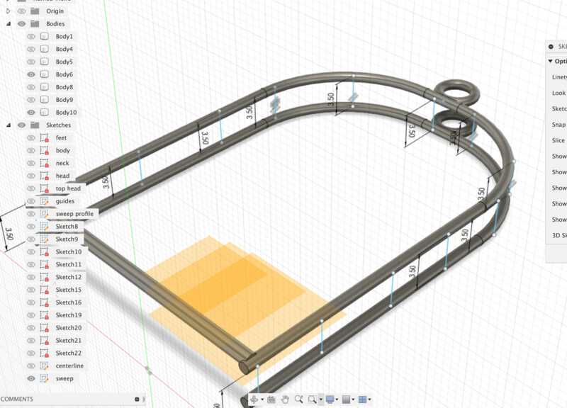
bird on a stick
After that, I proceeded to add feet (torusses) and a stick. Or actually, half of those, as I also found the mirror tool. I used a fit point spline to draw the ‘hanger’ half and used a sweep to give it body:
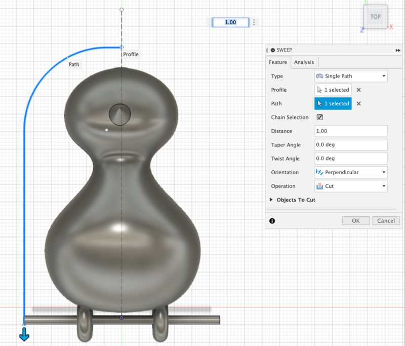
Then I added the tail:
I exported again and imported the .stl into PrusaSlicer. Because the stick part kind of hung in the air, I turned on the “support on base plate” option. This added a lot of supports, but also 30 minutes printing time and a lot of extra used PLA. I tweaked the “Expert” settings under “Support Material”. I changed the following settings:
- First Layer density: was 90% , set to 40%
- Interface Pattern Spacing: was 0.2mm, set to 0.7mm
This sliced about 5 minutes from the print time. And then I went for my second run on the Ultimaker.

The result was not bad at all! There was one problem however: I made the ‘feet’ too small, and the inside of the rings got fused to the stick in the print process. The material was also a bit too thin, and after trying to pry it loose, one of the sides broke off.
And thus ended my friday. With more result than expected, but not completely done.
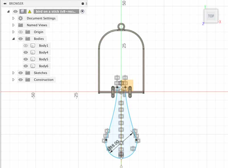
On monday I went back to Fusion360, to make the birdfeed a bit bigger. I discovered how to use “edit feature” in the process and made the torusses both a bit bigger and thinner.
I also sliced off the back of the bird. This brought the tail flat on the surface, lessening the needs for support. Because that made the bird body also a bit lighter, I tweaked the tail a bit, bringing it closer to the body and more rounded shape.
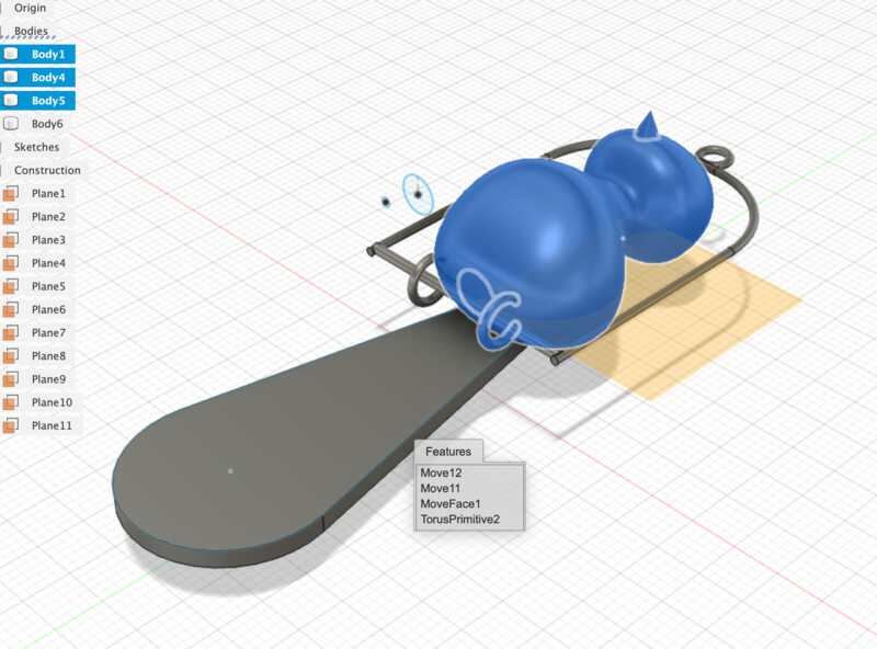
Instead of using supports fron PrusaSlicer, I tried to make my own struts for support. I mirrored the hanging stick part and proceeded to add little struts between the two. For this I enabled the option 3D Sketch in the Sketch palette
I came quite far, but realised that the rounded parts needed more work and more struts than I initially thought. So I abandonned this idea and opted for tweaking the Supports option in PrusaSlicer again.
Because I made the back of the bird open, PrusaSlicer now added supports inside the body. This was not neccessary, and luckily PrusaSlicer provided an option to block supports.
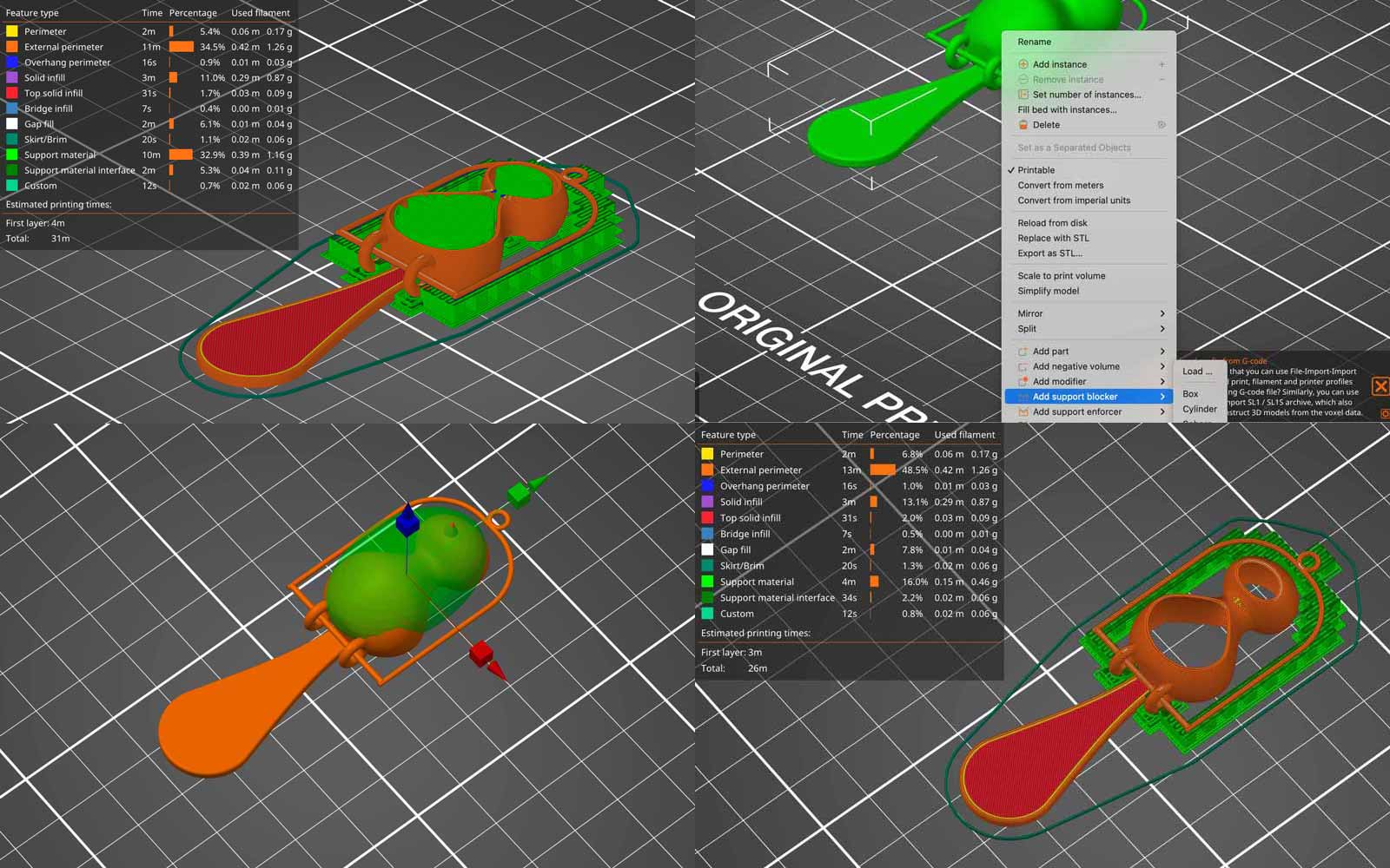
That helped a lot. I also tweaked again the Support settings:
- I set the option “Top interface Layers” to “light”
- I set the “Interface Pattern Spacing” to 0.5mm
- Turned on “don’t support bridges”
I exported g-code for both the Ultimaker and the PrusaSlicer. I noticed that for the PrusaSlicer, I had an extra option for “Style” : Snug instead of Grid. I turned that on for the PrusaSlicer.
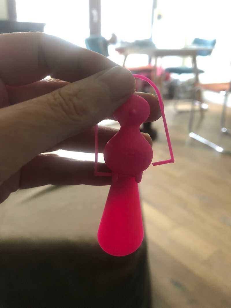
Then it was on to the printers again. First the Ultimaker. Printing went well. The supports made it look like it was a bird in a birdhouse :-)
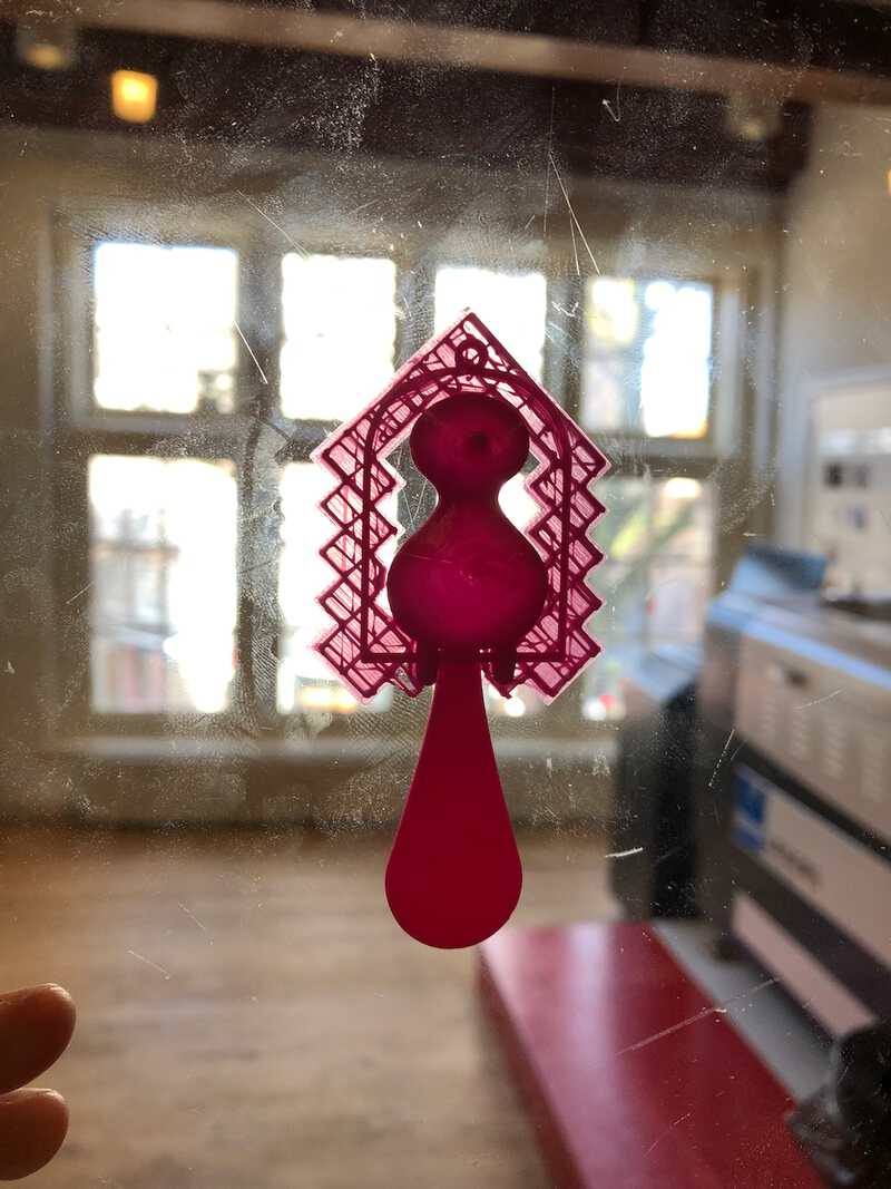
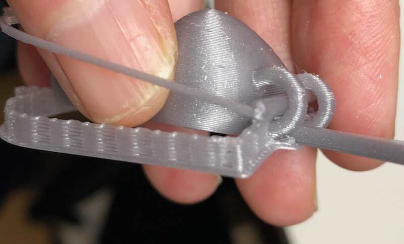
I removed the supports, this time without breaking the stick. I still had to pry away some filament inside of the feed though, and therefor the bird still did not move freely, although it was already much better. It hang a bit to the back, probably because of the placement of the tail. In the picture you can also see a little bit of stringing still.
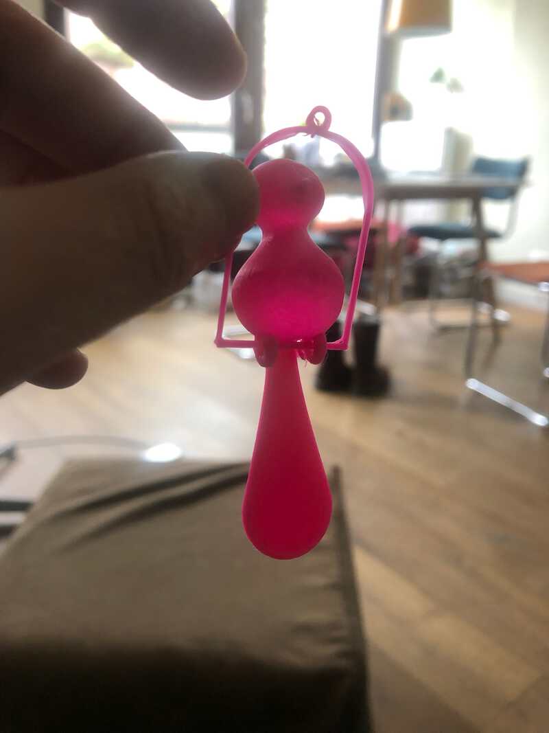
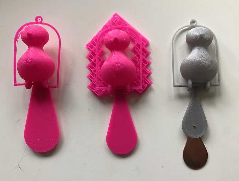
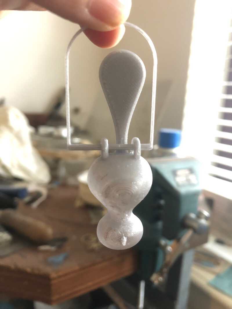
Next try was the Prusa. Because I thought the tail was still too heavy I made it much smaller. I also made the feet bigger again, and the sitting stick thicker.
Sander had just calibrated the Prusa, so I did not have to do that. Printing went without problems, and the bird turned out fine. The “snug” supports meant that it also printed about a minute faster, and used less filament. This time the feet and the stick were printed nicely without any connecting strings.
However, the decision to cut down on the tail proved wrong. This bird did not want to sit.
fixing the bird
I could have printed the bird again, but this time with the longer tail from bird #2 . Instead, I took the opportunity to fix this in another way. I tried to make the tail heavier by adding material to the back, but it turned out that I needed a lot of heavy material for that. So I took out my goldsmith saw and some copper plate and sawed out a shape in the same shape of the tail. I used some tape to stick it to the back of the tail, but it still was not heavy enough. I had to lower it quite a bit, but eventually it was enough to hold the bird up.
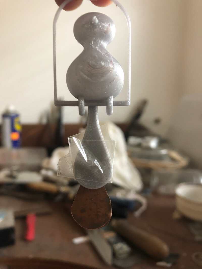
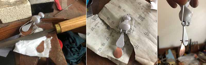
I filed the copper plate, and sanded it until it looked clean enough to function as a bird tail extender. I used a rivet to attach it to the printed bird.
Below is the final result:
sources
here are the files for this week
3D scan an object
For 3D scanning, I used the Sense 3D Scanner that is part of the FabLab inventory. This is a handheld scanner that is connected to a desktop computer that runs the Sense software. The software is easy to use, just press Scan and start scanning a 3D object by moving the scanner around it. The software shows the progress and when done right you see the object emerge on the screen.
It is however not so easy to scan. The scanner easily looses track. My first scan object is a white coffee cup with a Waag logo that I placed onto a stool. I scan the cup by walking slowly around it, keeping the scanner pointed at the cup and trying to keep the scanner as steady as possible. And trying not to get tangled in the cable that the scanner connects to the pc. It starts well, but after about one third of the scan the scanner looses track and starts to guess wildly and incorrect. By rescanning previous parts, you can sometimes bring the scanner back on track, but with the white cup I keep loosing the track over and over again. I think that a white smooth surface is just too hard for this scanner, in the light conditions that I have in the lab. There is probably not much to hang on to for it, and I abandon the cup and look for something better.
I try a red oil can, but that too has too smooth surfaces that leds the scanner to weird conclusions.
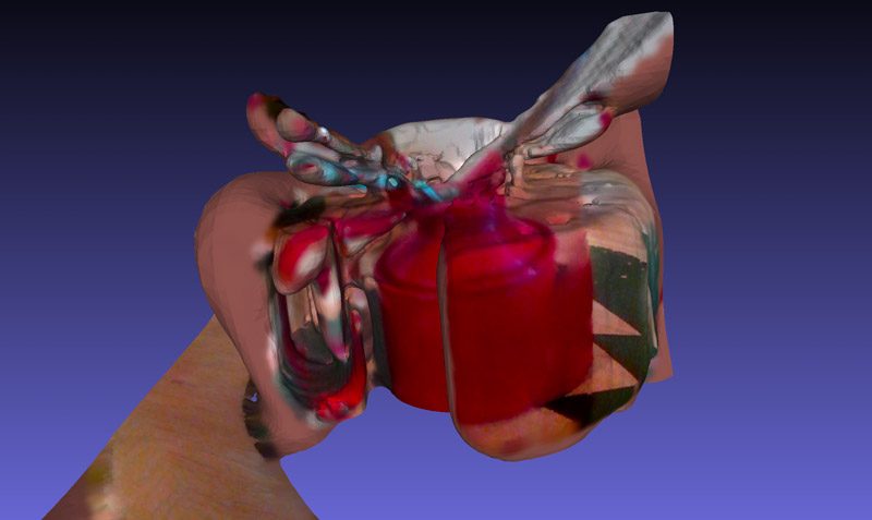
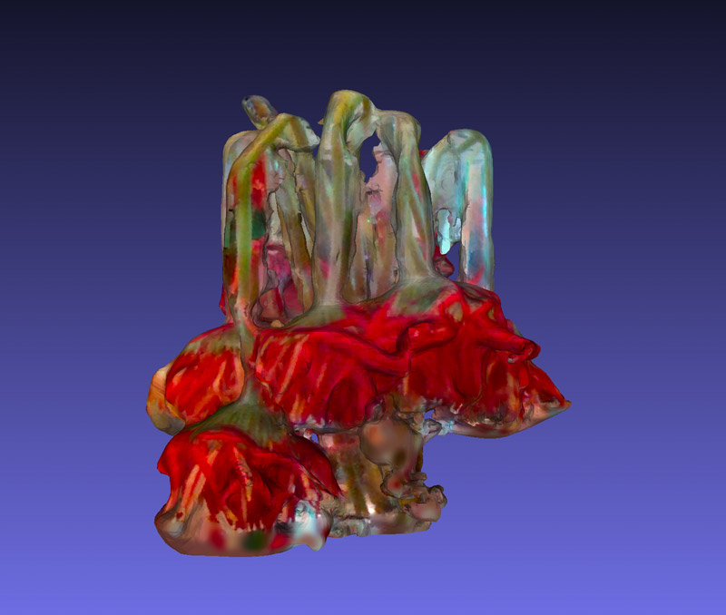
Then I find a little vase with a couple of dwindling flowers. Lots of colour and texture, so probably a better match for this scanner. I place the vase on the stool and start scanning. It indeed goes better. The scanner still looses track here and there, but with rescanning it will find its path back most of the time. I get the hang of scanning, realising that once the scanner is on track you can just move the scanner slowly from top to bottom left to right and the software will understand what part goes where. After a while I have a fairly recognizable 3D representation of the flowers on the screen.
I export the object as a 3D .obj file that I openend in MeshLab to create the below screenshot.
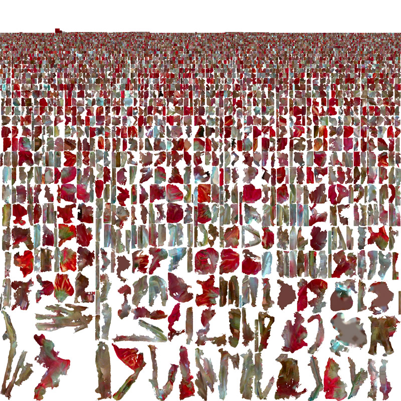
I also exported the object as a .png which results in a “flattened” object: mesh objects for all the sides. That in itself looks like a field of flowers:
looking back
This week I am happy with the initial planning. I started out with a simple design and test on friday, and since that went well, I was also able to add most of the rest of the design and even print a first draft with that.
On monday I had enough time to tweak and print two birds. I am happy with how the final bird turned out in terms of design.
The tail balancing part was a lot of guesstimating, and I made some wrong assumptions along the way. Making the tail shorter while in fact it should have been longer. But I am happy with the fix, and I really like that I was able to combine some old school techniques that I learned ages ago with this new way of making that I am learning today.
I still have a good 15 minutes read amount of documentation, so in the respect of being more concise I was not succesful.