The task list for this week:
- Group assignment:
- Design a machine that includes mechanism + actuation + automation.
- Build the mechanical parts and operate it manually.
- Document the group project.
- Individual assignments.
- Document your individual contribution.
Group assignment: Introduction to machines.
Our machine's name is Mudrak. which is a Marathi(our Local language) word for Printer. This Idea credit goes to Kiran sir. He put this Idea into making a clay printer Inspired by a TEDx video by AnnMarie where she Introduce how to make conductive clay to make circuits for children.
TEDx video by AnnMarie where
So the Idea for our machine was to make a CNC machine which can print this circuit using clay.This is a short introduction to Mudrak. have a look at the following video.
Introduction to Mudrak.
Some of Our Hero shorts.:
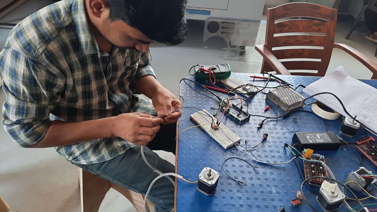
We all work together to make this machine possible .where every individual puts their effort to perform his role and contribute to the team. These are some of our photographs during the development of the Mudrak machine.
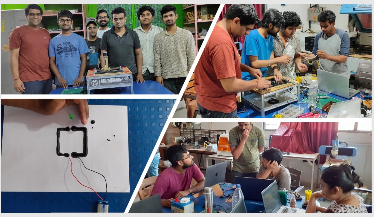
hero shorts with group.
Group assigment link.
Individual contribution.
Process flow for machine bulding:
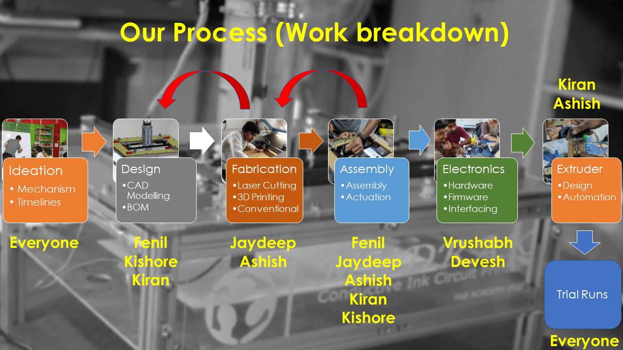
Process flow for machine design.
For this week, there are many tasks to do and we all know a single person can not make this all possible. so we start finding our expertise and define our role during the development of Mudrak. which you can see in the following image. I have already experience with some Electronic .such as running stepper motors and familiar with some CNC machine making from my college projects. So I decided to work on making electronic hardware part of the Mudrak CNC machine. As hard were and Software works together I also work with Devesh and with Kiran sir while making Conductive Ink.
Selection of electronic components:
For studying we refer to many CoreXY CoreXY based CNC plotters; they all have a common set-up. Which is as follows.
- Stepper motor.
- Stopper Driver.
- CNC Stepper Driver shield.
- Control board.
- End Stopper switch.
- Power supply.
So from what we have and what can be available, I started to build the Electronic. We mainly focus on getting the parts components that have strong community support.
Selecting the stepper motor:
As per the requirement of the mechanical design team. I selected a Nema 17 with 5.5kg-cm torque to drive the motor Axis. we select 2 for running the XY axis in core XY and one for Extruder of the same configuration.
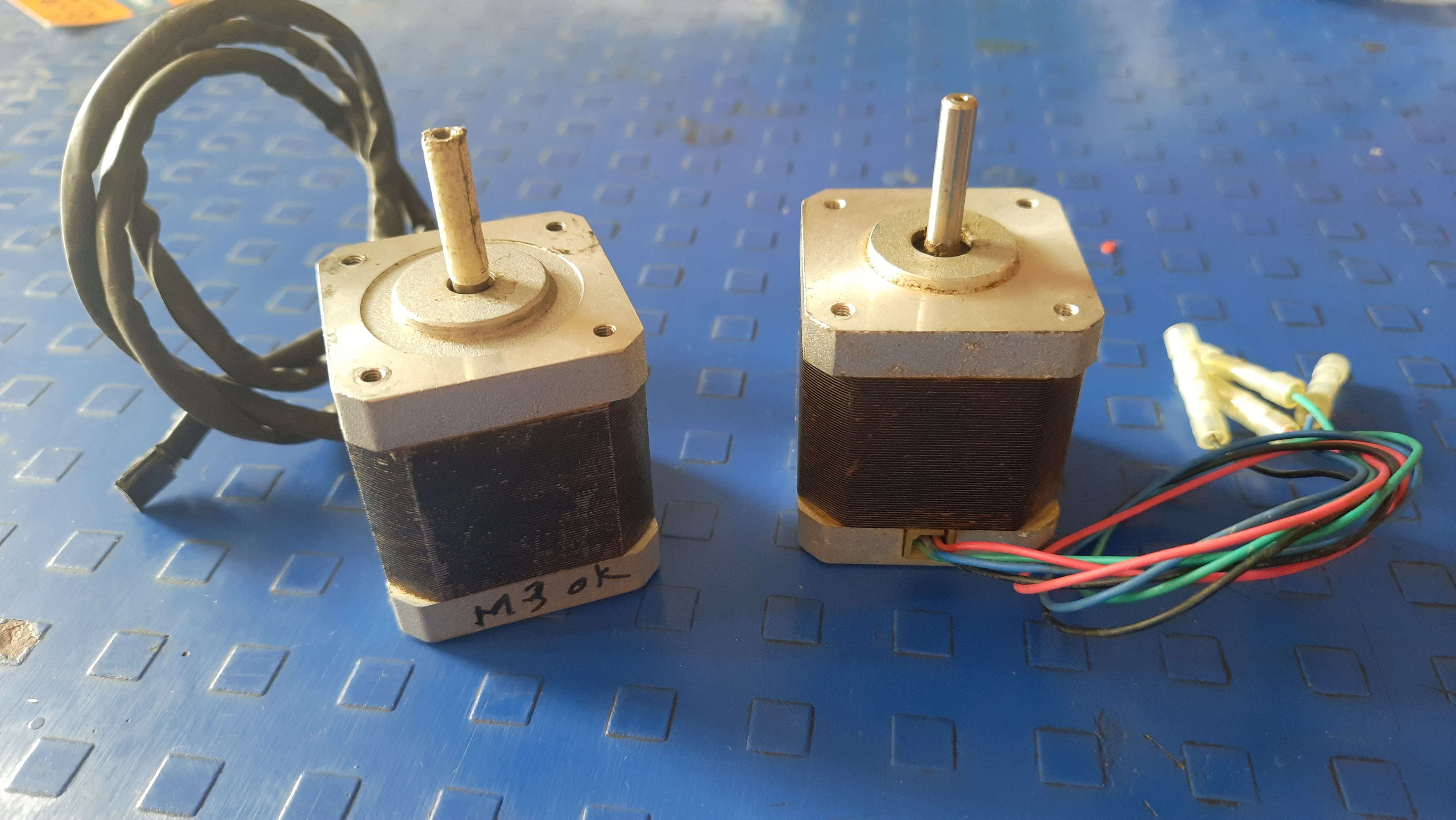
Nema 17 with 5.5kg-cm.
For more data, I refer to this datasheet of NEMA 17.
Selecting the stepperDriver:
For running the stepper motor I will require a Stepper driver. For which I could have many options. But after discussion and considering the
Marline driver configuration availability and what we have in the lab we go with A4988as a motor driver. As it fully fills all the needs to run the motors.
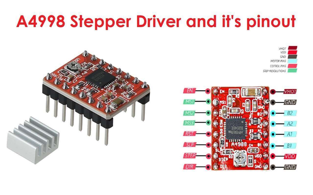
A4988 Stepper driver.
For more specifications, I refer to this Datasheet on the A4998 Stepper motor driver .
Selecting the CNC stepper driver shield:
There are so many types of CNC stepper driver shields Available in the market.Out of which we have Arduino CNC V3 shield, Ramp MKS 1.4 V, And Ramp 1.4 CNC shield.
I select ramp 1.4 CNC shield because we have it more than one in our lab and also because of its strong community support.
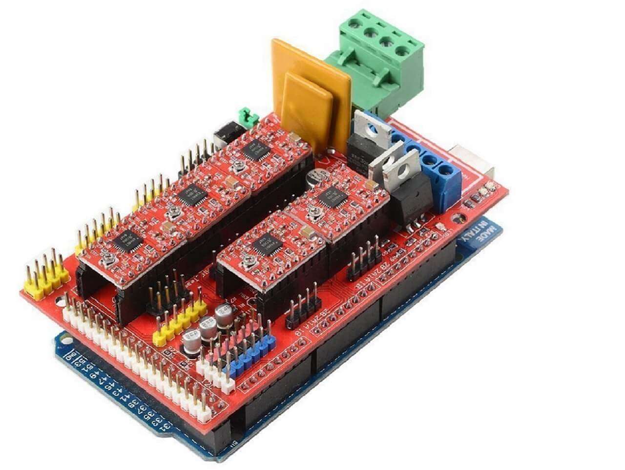
Ramp 1.4 board.
For more specifications, I refer to this guideline on the Wikipedia on Ramp 1.4.
Selecting the controller board:
As the ramp 1.4 boards are built for Arduino mega 2560 we have no other option for selecting the controller board.
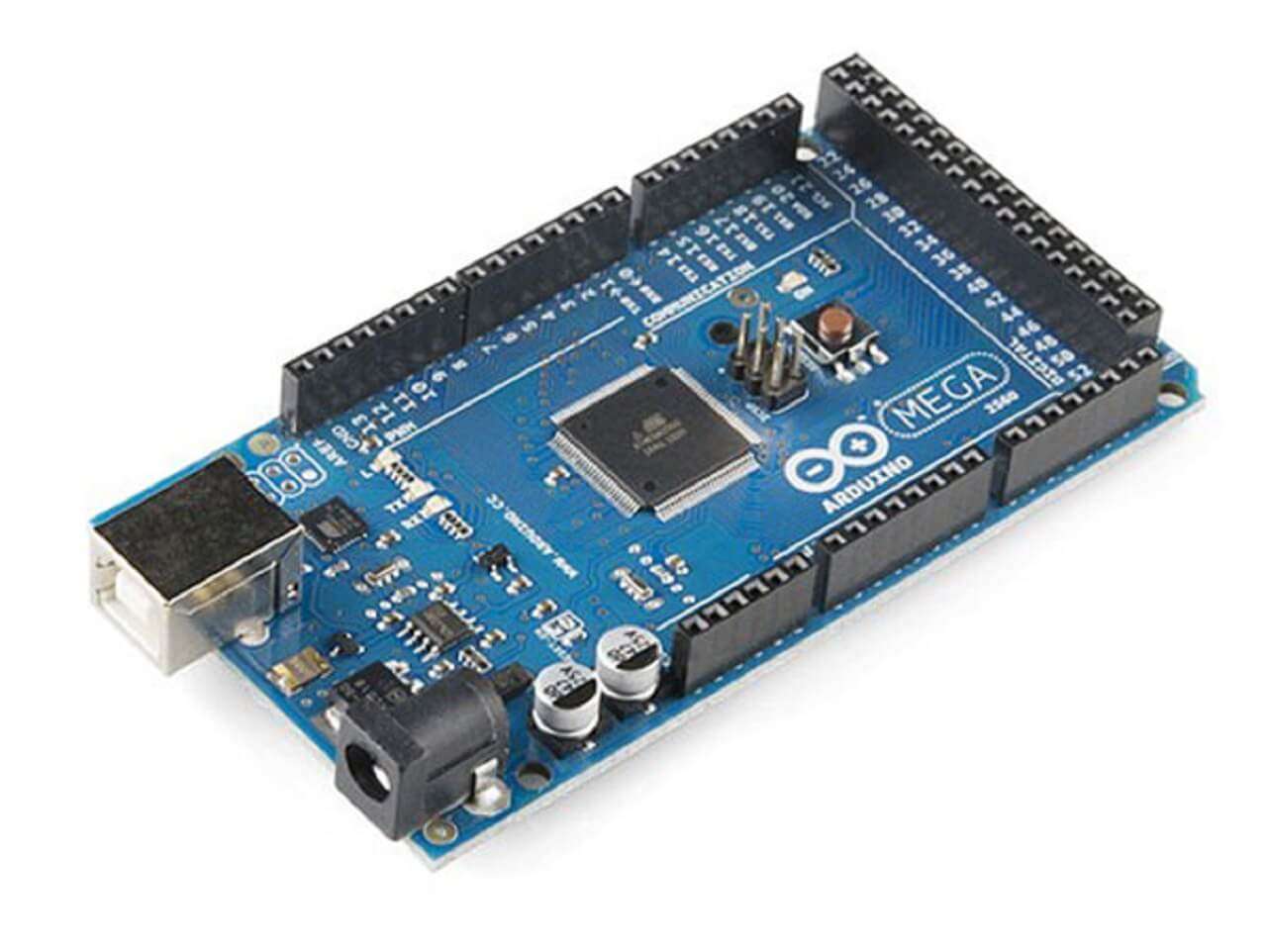
Arduino Mega 2560.
For more specifications, I refer to this guideline on the Arduino Mega 2560.
Selecting power supply:
As per the requirement of current consumption and voltage requirement for electric components for our machine I chose 12V 5A power more adept for powering up the machine.
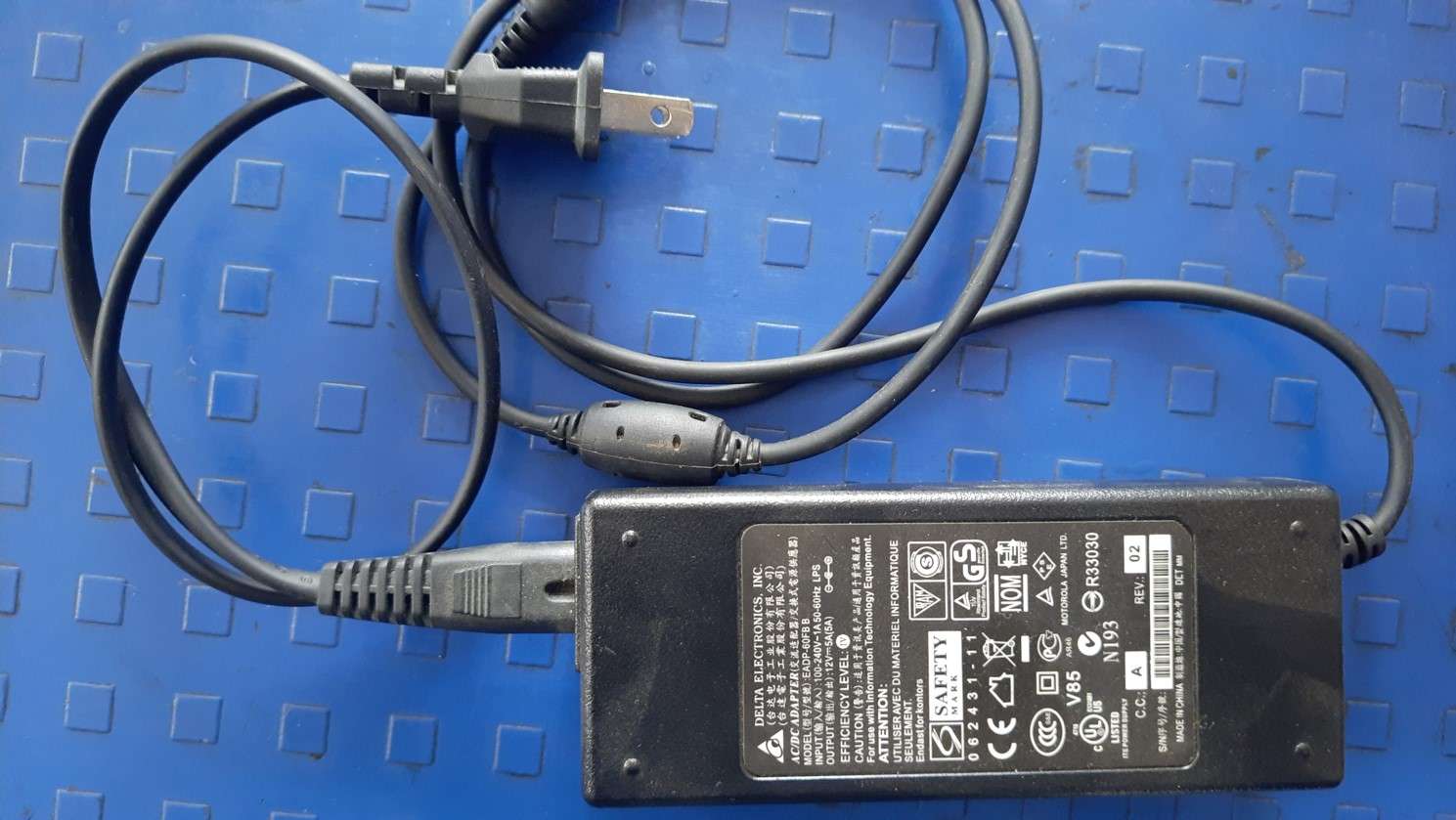
12V 5A power supply.
You can check the power supply specification I refer to this Power supply datasheet.
Testing of electronic components:
Testing stepper motor and stepper motor driver:
I want to test the stepper motor for setting up our electronic conductive Ink printer. As we are going to use marlin firmware but it is not ready. So I decided to test the stepper motor first. We start with testing individual stepper motors for which I refer to a blog from last-minute engineering "Control Stepper Motor with A4988 Driver Module & Arduino".
Making connections for stepper motor.
Code I use to run the stepper motor.
We test it and all the drivers and motors work properly when chek individual.
Testing stepper motor with ramp 1.4 shields:
After testing motors individually. I tried to run them on the Ramp 1.4 shield. For that, I refer to this site about ramp 1.4. I assemble the motor drivers on it. Attach the 12V 5A supply to the board and set everything ready to test except the code. I use the same test code to try to run the motor on-ramp shield checking the dir and step pins from the schematic diagram of the ramp board for the X-axis motor. To know the pin no. for X-axis I refer to the ramp schematic diagram of the ramp. for X it is A0, and A1 for dir and steps respectively and uploads the code but it does not work. Then we check for supply for the ramp bord we check the driver supply 12 and 5 v and also the cable output testing continuity and lock testing. After several trials to run a stepper motor on Ramp 1.4 Finally I got this ramp lib Ramp-master which helped me in running the steppers using a ramped board.
.jpg)
Ramp 1.4 connection output design with various components as referance .
Above is a general connection output of various components with ramp shield.Which I prefer for connections also.
I use the
code
from Examples in liberty and custom it according to me to run a motor and in this way, I test motors on-ramp shield.
Arduino code used to test motors.
Costum Ramp shield Code.
All these steps helped me in running the steppers using ramp board successfully before configuring the hardware with Marlin.
Stepper motor with Ramp 1.4.
Connecting Electronic with Ramp1.4 for CNC:
For Running marlin on the Ramp1.4 bort . I have to connect all the components on the Ramp1.4 shield. Below is the circuit diagram of all components and their connection for the Mudrak CNC Ink printer I make. I assemble all components as per the design below . .
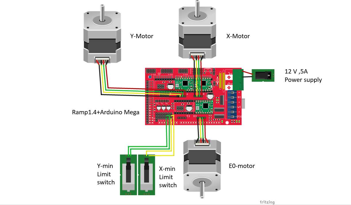
Final Electronic Circuit design.
For End Stoppers, I use a Mechanical switch With 2 pin direction connection as shown in the below Image. Most of the CNC configure their End Stoppers switch in their min position. And the bed distance can be set through the firmware itself. So we need just 2 limit switches . One for X-min and another for Y-min.Because of the
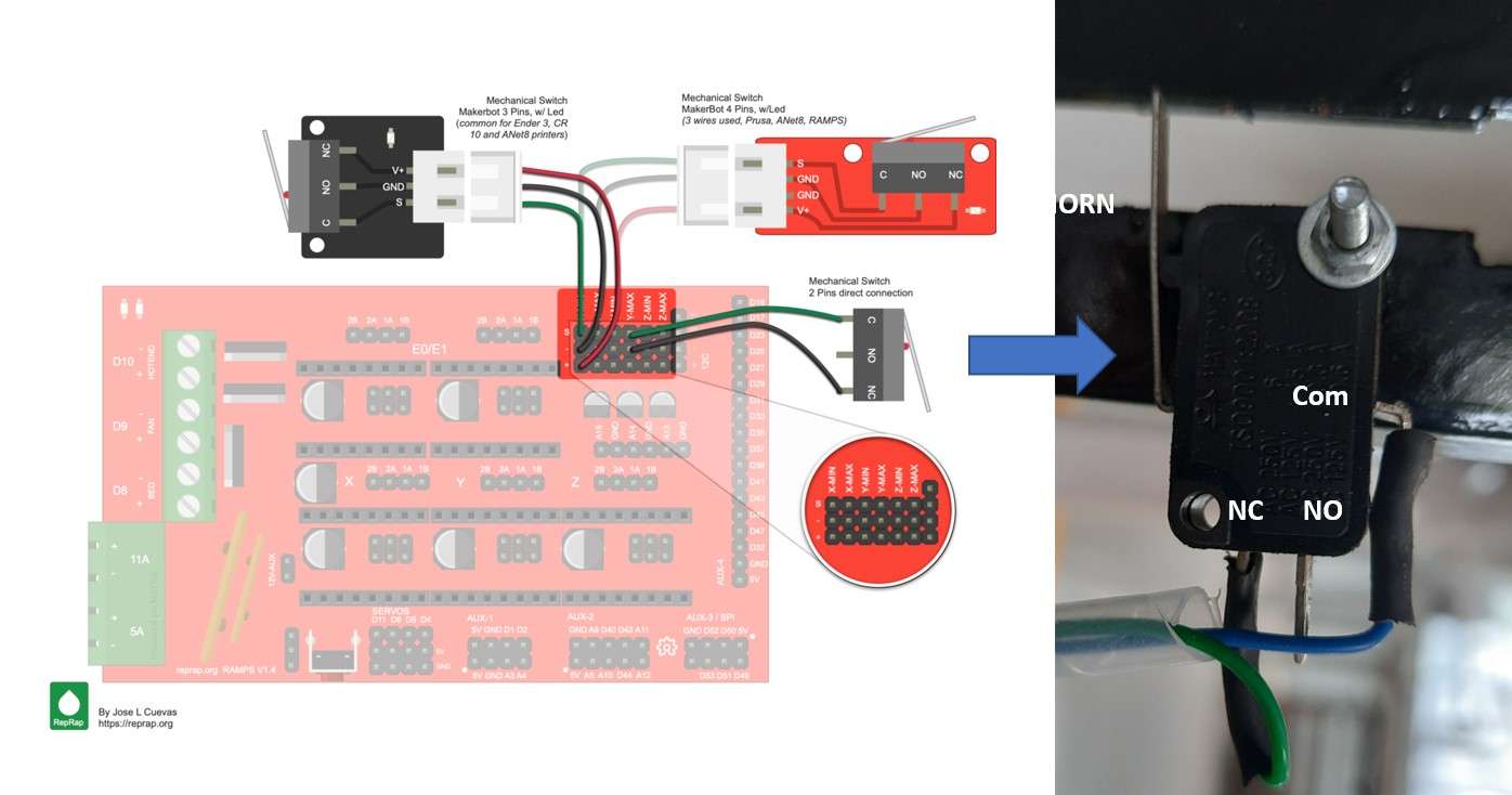
End Stoppers connection.
Testing Steper motor with Marlin:
Selection of Software part:
So after a long dissection, we all came to the point to use
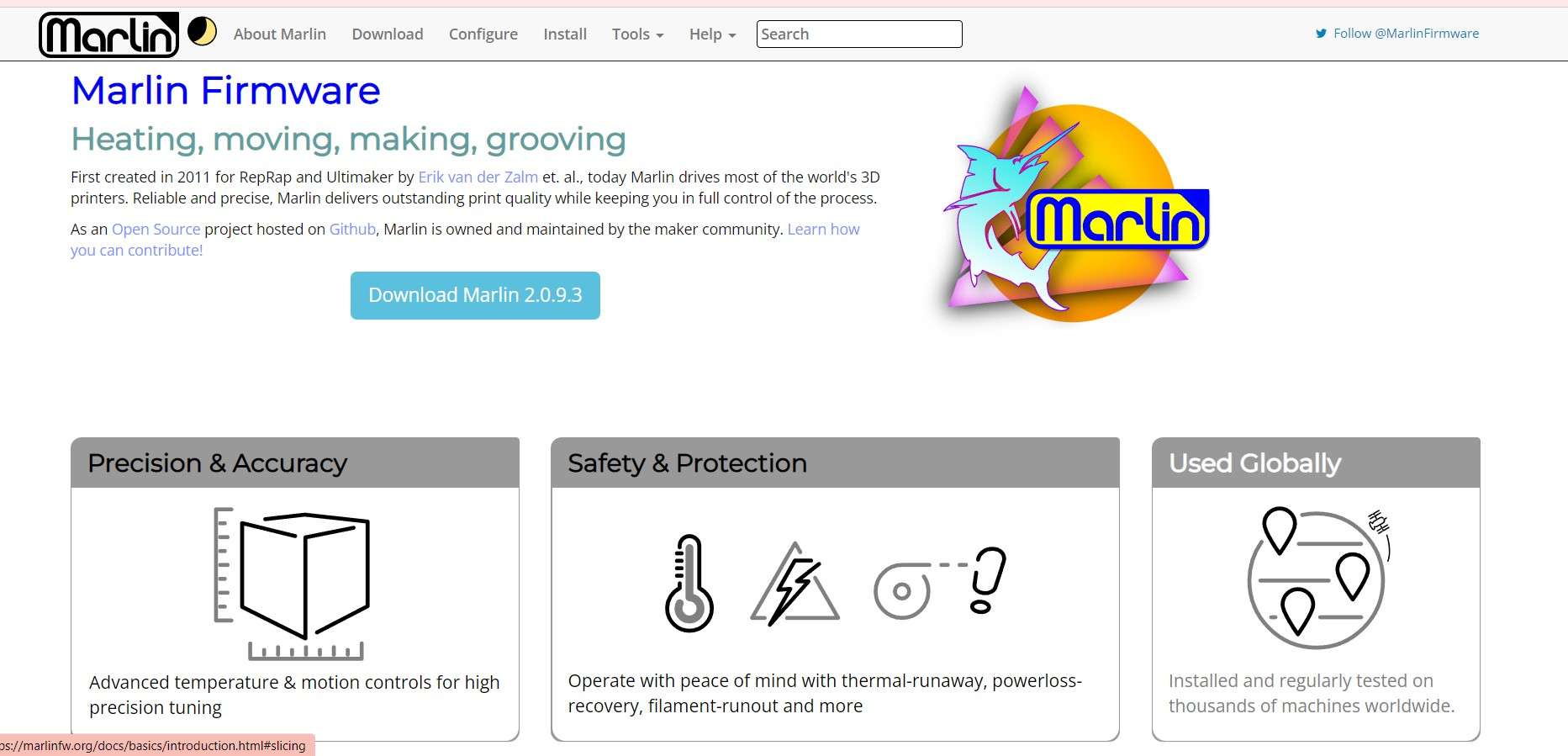
Marline
as a base firmware for our CNC clay printing machine.s It is popular one and It has a lot of support from the community.
You can read more about marline in
Devesh's blog.
So currently we will focus on my journey of setting up the electronics for our machine.
Process flow for machine design.
Updating the firmware:
After all connections are done. I also help to make changes in marline configuration . Rohan one of our local instructors helped us lote in customizing the marline firmware and devices and also make all troubleshooting with me to run the hardware using marlin. To read more about marline customisation for our CNC machine please refer to the Devesh's blog.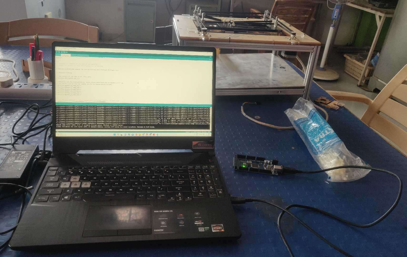
Uploding Marlin on Arduino bort.
I upload marline on an Arduino board. (note remove the ramp shield during uploading the code) and use Pronterface to control the firmware.
Testing and controlling the motors using marlin:
For testing and controlling the motors, we used a software interface called
Pronterface
.This interface allow you to connect and control your shield with the PC. The image below shows a Glimpse of Pronterface.
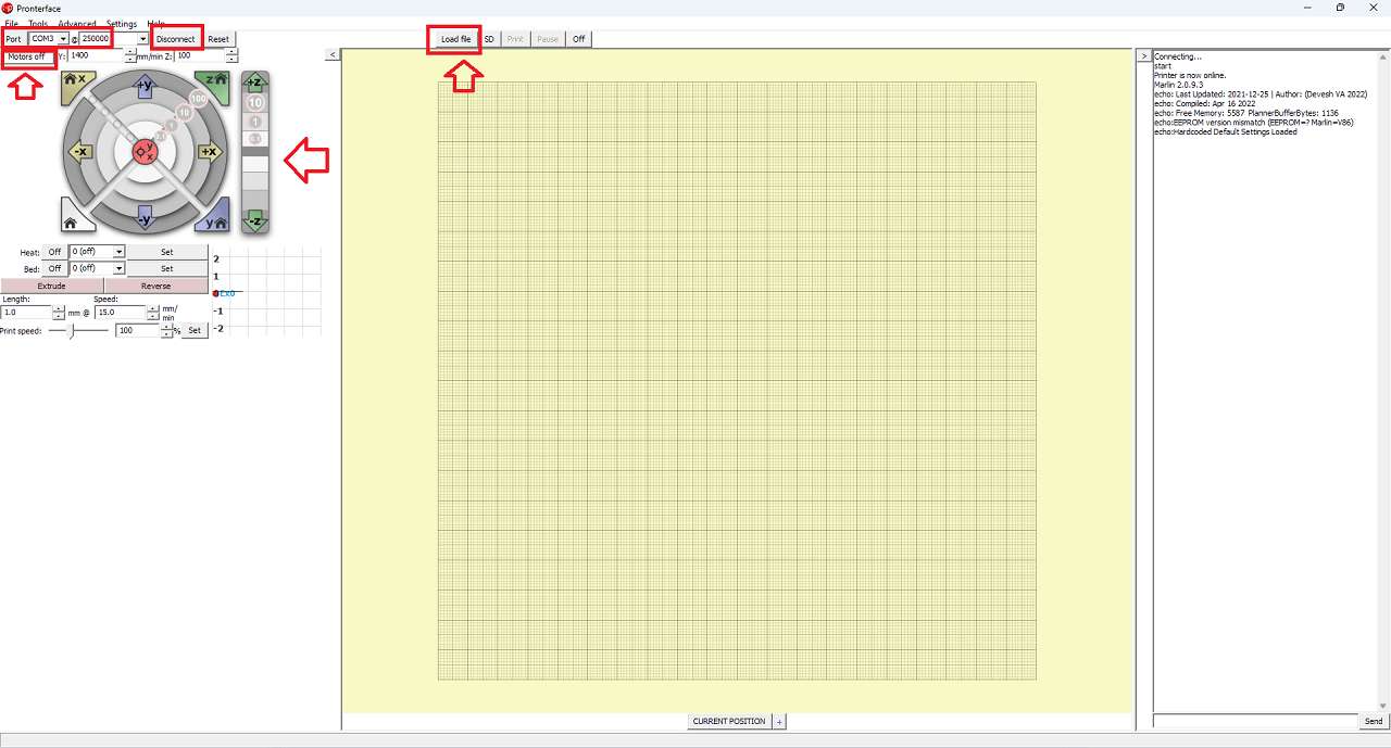
pronterface.
I first install the Pronterface on my laptop. The interface is very easy to use Below are the steps I use to connect the hardware with the Interface.
- To connect the interface first run the application on the laptop .then connect the hardware(Ramp shield with all components) to the COM port using the Arduino programing Cable.
- Select the COM port just like in Arduino IDE we do to make communication between Pronterface and Arduino.
- Click the connect button just right to the com port to make the connection.
To check the motor I first obviously connect all the 3 Stepper motors and use motion control keys on the interface to see all the motors are working properly. Some motors were moving in the opposite directions so for that, I just invert the pins and make them revolve in the right direction as per required for the Core XY mechanism.
Controlng motors using pronterface.
Assembling Electronic on the machine:
Finally, after ensuring everything is working nicely. It's time to assemble all the components on the machine to make it Move. In the below image, I define the position of all the electronic components I have to assemble on the machine.
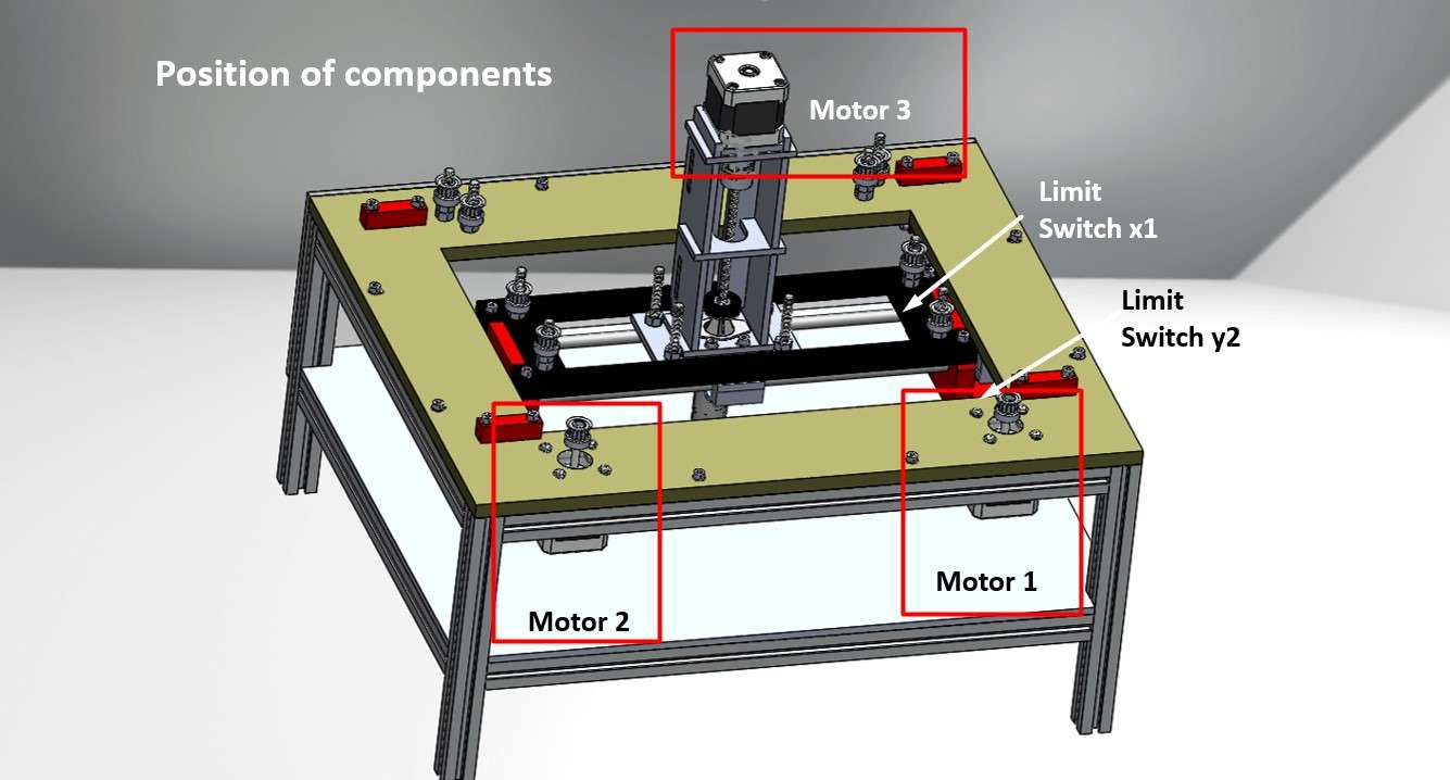
Components position on CNC .
All the 3 NEMA-17 were already assembled by Ashis and the assembly team. Everyone from team manly Ashis, Kishor and Jaydip helps me in Routing all the wires on the machine. I assemble the Ramp1.4 shield with Arduino at Corner on an Acrylic Plate . And connect all the Wires from the motors and limit the Switch using a wire rap and cable zip tie.
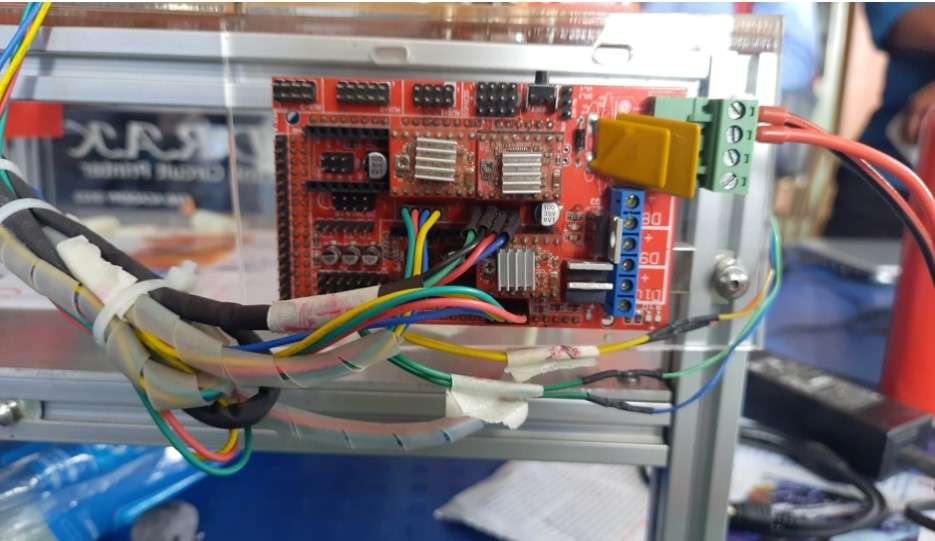
Wire Routing and connection with Ramp1.4 Shield.
Final Testing on the machine:
And here is everything working.
Final testing of machin.