Objective
Design a machine that includes Mechanism + Actuation + Automation + Application
Build the mechanical parts and operate it manually
Document the group project and your individual contribution
Introduction
This weeks activity was just awesome I just loved it! This week was callled make a machine week also called as machine design,mechanical design. It was really a chllenge to build a machine in a week technically two week if you include the break. I had a lot of work pending on the line and might not even make it to the midterm review. But it was awesomw!
As the objectives state we had to build a machine which could Actuate,Automate and fullfil an Application. It was a group task and had alot of efforts on the line. I hope my midterm reviews go on smoothly.
The action plan
The action plan was to build a cnc machine in the given stipulated time but the take everyones' strengths and utilize all the resources that we have.
First we did a brainstorming session the divided the plan into different sections and then formed teams to execute the plan. It sounds simple but trust me its not that easy.
Working in a team means managing alot of things there will be members who have a different way of working getting everyone to sync is a major task. I guess we are still figuring out about the ins and outs of our plan.
The machine plan was divided into 3 parameters
- Mechanical Desing/Assembly Section
- Electronics Section
- Extruder Design section
Please note these things will be metioned in the group assignment page in a proper manner this page is for personal reference only.
Results after brainstorming and the issues
First I created a repository on git hub to log some of the work.
After the brainstorming session we got split into teams and started with a bit of literature review.
I chose to work on the electroninc side of things along with my friend Vrushabh who had a bit of experience assembling a 3d printer before.
During brainstorming session we had some puthforth some questions on the table to streamline our goals.
They were :-
What is its purpose?
What are its dimensions?
Will the printer have an interface?
What materials can be used for building the parts?
Extruder?
The Answers were
Application is to print conductive clay on a surface
Bed Dimension :- 200x200mm
Axis:- 2 Axis
nterface might be according the time management
Aluminum frames and old slavaged parts of another projects, acrlic etc.
Extruder :- Syringe
Firmware:- Marlin
Though we had answer they were to some of the questions but we had alot of research to be done. Discussions were fine but we couldn't carry out the supply side of time management.
Status Update
Date 8/4/22
Update 2.0 Electronics section We tested the ramps shield with all the components that was shown in the tool list.
The files for marlin were also compiled. The link to the archieve will be posted after sometime.
Progress was slow but significant. Next part is to control the XY motors to perform an operation using a software like pronterface.
The software has issues with MacOS 12 so searching for other alternates also.
Date 12/4/22
We were able to take a test run of our motor on the gantry but still had assembling issues.
The gantry movement experienced a jerk finally an observation was made that we need an extra pair of linear bearings and had have to make changes in the design of corexy machine.
Now we have decided to use some 3D printed parts and salvaging the delta printer that we have at our lab.
Date 13/4/22
The assembly was complete now it was of to the electronics team to do the job. Initially we go stuck on the software and hardware level but eventually came through.
Working through the night to figure out the XY movement of the motors.
XY motion complete next homing position with endstops.
Date 14/4/22
Homing challenge complete
We setup all the movement and positons now ready to test with the extruder.
Date 15/4/22
Extruder setup complete,the calibration was also done.
Created the gcode files necessary for the circuit about to be printed
Made a plan for presentation.
Electronincs Section
What we did?
First through the brainstorming session we narrowed out our software pick to Marlin. Therefore this enable us to focus only marlin for a couple of days and gave us a headstart.
Marlin firmware was spun-off in 2011 for Reprap and Ultimaker by Erik Zalm. It is the perfect firmware for our needs highly customizable and easier to compile.
The best part is that it still supports older ramps shields which was available in our lab. The downside is that the code is a bit heavy and the compile times are higher than expected.
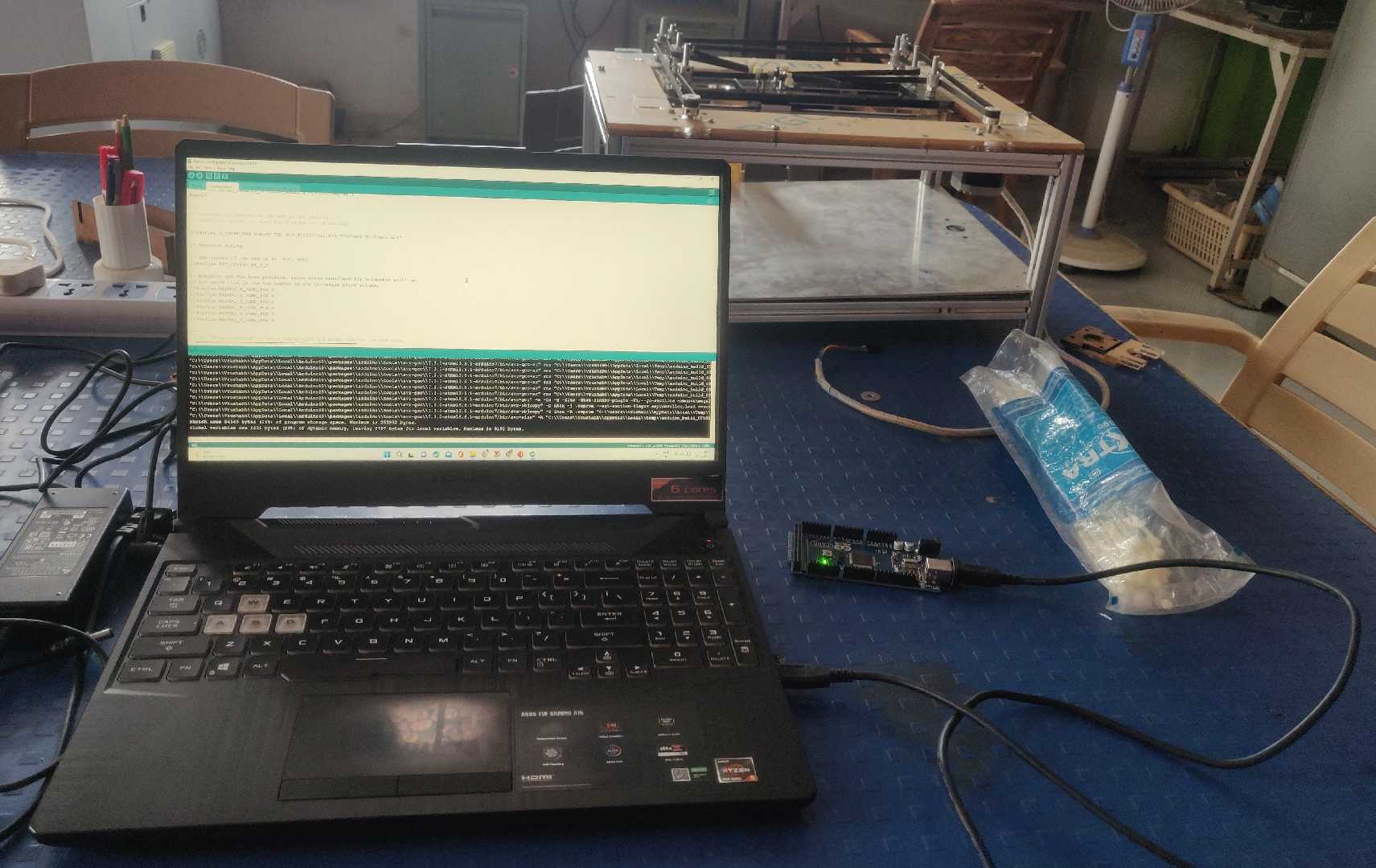
After making some changes to the code the user has to wait for almost 10 minutes to compile and upload the code to an Arduino Mega development board.
Though there were other options for the hardware selections we were just beginners and want to try something on already test hardware for better support.
The RepRap community is huge and has alot of fixes for the issues it was like a treasure trove of knowledge.
Marlin
To get Marlin files head on to Marlin website
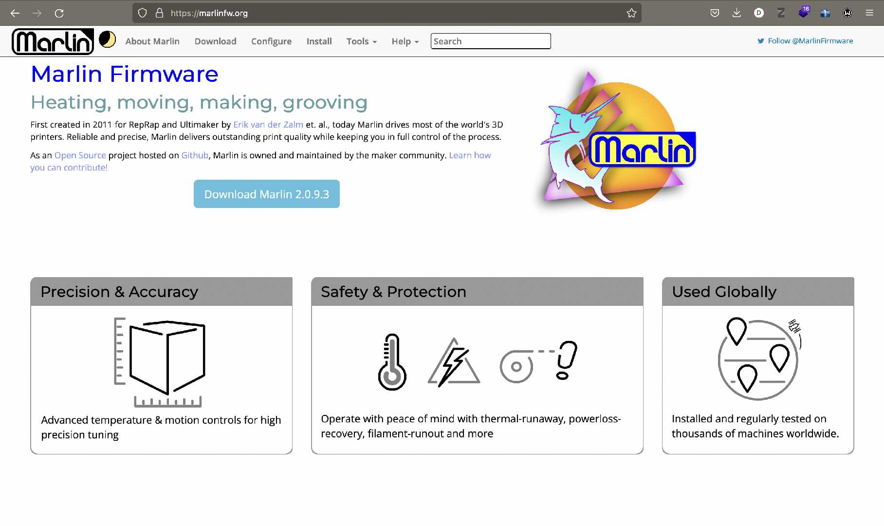
Follow the steps involved and choose Marlin Ver 2.0.9.3 while downloading in the downloads page.
Your marlin files will appear in the downloads folder.
Extract the folder
Extract the folder and locate the Marlin folder in it and search for Marlin.ino file which opens up in Arduino IDE.
When the file opens there will be a total of four files opened simultaneously one of them would be Configuration.h and another is Configurationadv.h
These are the files that contain the code for marlin firmware shown below.
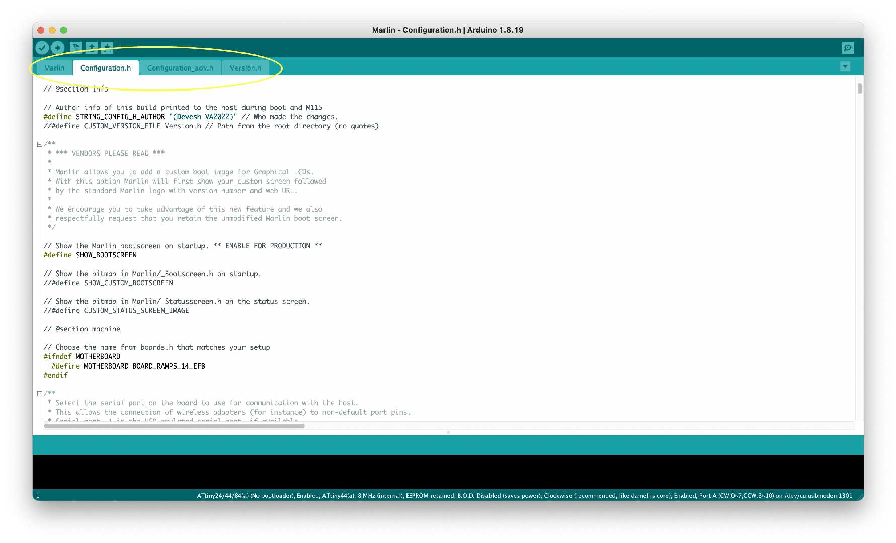
Edit the necessary parameters, compile the code boom your barebone firmware ready.
An image showing the upload process to an Arduino Mega above.
List of Electronic parts
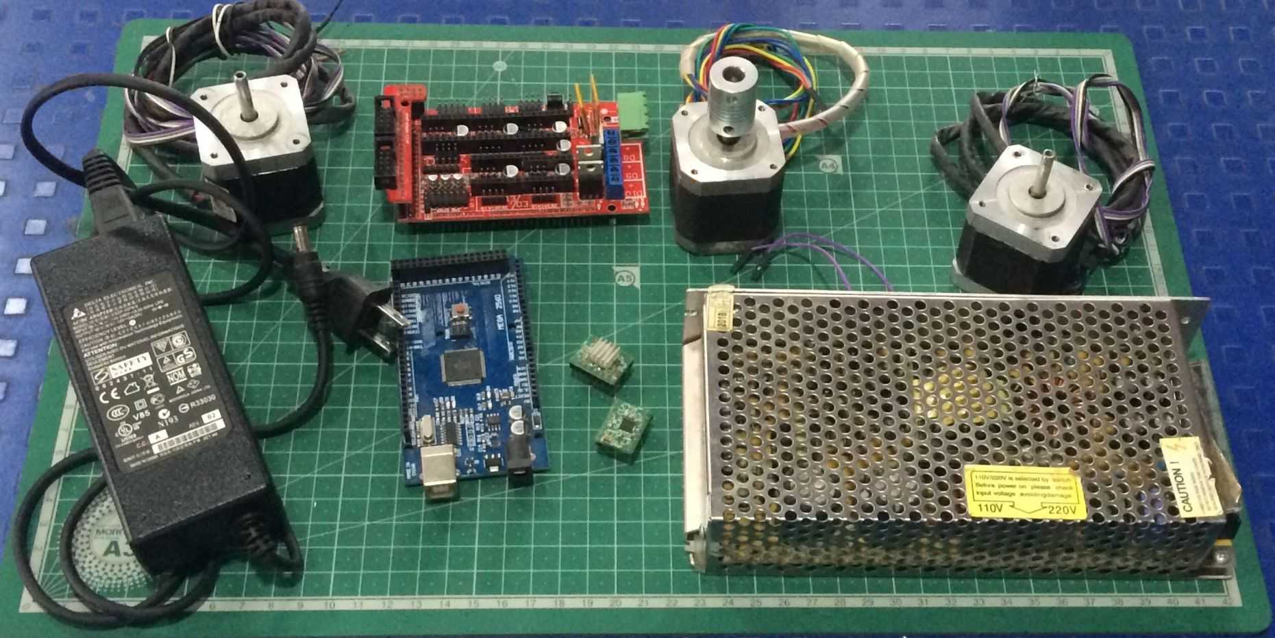
| Part | Qty |
|---|---|
| Stepper Motor | 3 |
| A4988 Motor Driver | 3 |
| Power supply | 1 |
| Jumpers | 10 |
| Endstops | 3 |
| Ramps Shield | 2 |
| Arduino Mega Development Board | 2 |
Customise the firmware
Customizing the marlin firmware was easy but there were some bits that even we didn't understand like giving the temperature setting for the extruder etc.
Marlin is highly customizable but I had to seek help of my instructor initially to get my hands dirty on the code he was the one who recommended me to use Arduino IDE to compile the firmware.
In the end after two days of compiling and debugging the firmware was ready to be tested on the assembly. Below you can see a video of us compiling the software initially.
Testing and calibration phase
For testing and controlling the motors we used a sofyware interface called pronterface.
This interface allow you to connect and control your shield with the PC.
The image below shows a Glimpse of Pronterface.
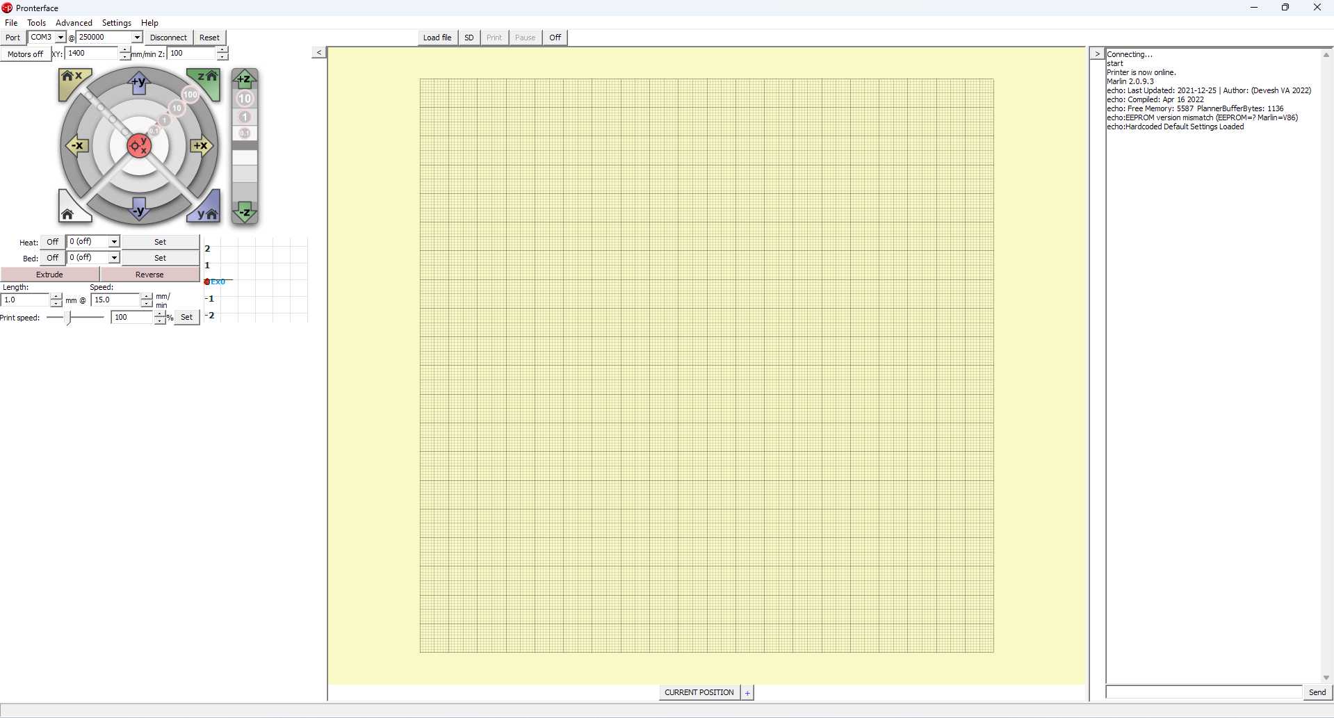
To use pronterface just connect the shield first to the PC and then run pronterface on the machine.
You will see the com ports define on the top left with the baud rate
Click on the 'Connect' button you will notice that the shield will provide some information about itself through the firmware and says its connected.
Control the motors and check if the hardware is working with the software by clicking the xy and z axis controls if necessary.
Through trial and error now we can determine the direction of the machine if any
For calibration and feed rate we used the prusa calculator to set our values and have and made a bit of trial and error cases also.
Then finally we created a printer that could print according to what we imagined.
Points that we recorded during the project
Then take the board that you are using in this case it is an arduino mega and a ramps shield. Note:- Do check the support list on Marlins site about the hardware that you are going to choose. Compile and Upload the Code on to arduino mega. After uploading download Pronterface. (Pronterface is a software that provides an interface for controlling the motors of our machiune.) After installing pronterface open and click connect to connect the Mega cum Ramps to pronterface to control the motors. Check the movement of the motor. Check the stepping. Mount the motor to the gantry assembly and check the XY movements. If the gantry isn't assembelled properly there will be a jerking motion on XY movement else everything will go soomthly. Check the extruder motions. After this the next step is to set the homing positions of the machines using Endstops.
Some Important G and M codes
Machine codes like G code and M codes are used to control a cnc machine through a CLI in pronterface we could individually send G code and M codes to setup the homming and perform other functionality.
Here I'm leaving a link for the reference of G codes and M codes
G28 - Homing position
G90 - Absolute positioning
M0 - Stop
M1 - Sleep
M2 - Program End
M12 - Enable stepper motors
M30 - Program Stop
M84 - Motors Off
M114 - Get Current Values
M428 - Set an arbitary Value
M500 - Stores the set value
My Experiences
This week was a bit overboard I couldn't keep up with the pace. I'm sure that my midterm review will be in jeopardy. Trying to keep up the pace is tough enough.
In the end I learnt how to build a machine and thats that. It was a nice experience for me and I will continue to push forward as time goes by.
So an hectic week and a packed task happy reviewing.
For the detailed view of the make a machine assignmnet I'm leaving link to the group page
References and Links
These are the links and references that I used
CoreXY
RepRap
Marlin 2.0.9.3
Hardware Support List
M Codes G Codes Theory
Calibrations
Homing and Offset
Pronterface
Prusa Calculator
3D printer Video from Mumbai

Fabspace by Devesh S Nair is licensed under a Creative Commons Attribution-NonCommercial 4.0 International License.