Wildcard week
Introduction
With This course, we can genuinely make almost anything. with this wild card week, we can do the things we have in our minds and not covered in the earlier assignment. Long ago, I visited https://elementslearn.com/ website built by MIT Design x Lab, which explores cyanotype and photographic experiments. I was fascinated by this and wanted to do this from that time. But with this course, I could do it for this assignment. The essential requirement of this course is to design and produce something with a digital fabrication process (incorporating computer-aided Design and manufacturing) not covered in another assignment. I have decided to create the fab lab logo for my college, Fab LAB, and print it on my T-shirt using Cyanotype printing. I also experimented with a plasma cutting machine to create trays for the Dome dryer available at the Vigyan Ashram.
Cyanotype
The cyanotype is a low-cost, slow-reacting photographic printing formulation sensitive to a
narrow band of near-ultraviolet and blue light between 300 and 400 nanometers, known as UVA
radiation. It creates a cyan-blue print that can be utilized for art as monochromatic artwork on
various surfaces, as well as reprography in the form of blueprints. The technique typically
employs only water and two chemicals to develop and fix, ferric ammonium citrate or ferric
ammonium oxalate and potassium ferricyanide.
Sir John Herschel invented the Cyanotype printing in 1842, it has the merits of being cheap,
easy, and substantially non-toxic.
I have referred following references for preparing solution and procedure for the printing.
Photography
- Cyanotypes
Blue and White
How
to Make Cyanotype Prints of Your Digital Photos at Home
The New Cyanotype –
Cyanotype II process
February 20, 2010
Solution preparation
For the Cyanotype Printing, we required Ferric ammonium citrate and Potassium ferricyanide. Both
are in powder form. I have taken 22.3 g of Ferric ammonium citrate and 7.5 g of Potassium
ferricyanide as per the references. Then, the different solutions were prepared by adding two
powders to the 100ml distilled water beaker. Both the powder was added to the 100ml water beaker
and stirred well. Then, both the solutions were mixed in the 3rd beaker and stirred the solution
well. Then the prepared solution was placed in an airtight container and placed in the Darkroom
or brown bottle to avoid exposure to daylight or UV rays.
Stock Solutions: We have prepared the solution and stored it in an airtight container.
Solution A: 100 mL distilled water at ~21 °C
22.3 g Ferric ammonium citrate (brown colored)
Solution B: 100 mL distilled water at ~21 °C
7.5 g Potassium ferricyanide
They mixed these two solutions and placed them in an airtight container in the black carboard
enclosure to avoid daylight exposure.
We have created the Darkroom for performing the printing.
Placed the mixture of two chemicals with a 1:1 ratio with constant stirring and placed them
in the Darkroom with black exposure to avoid daylight exposure.
.webp)
.webp)
Experimental Trials
For the trial experiments, I have taken A4 size paper. Then ¾ layer of the final solution is coated on the paper and hung to allow it to dry. After 14-15 minutes of drying of paper, paper cut. We want to print vinyl cut, placed on the paper and paper placed in the sunlight for 15 minutes. After that, the paper was allowed to keep place in the water tub, and the template portion exposed to sunlight started glowing blue, and the remaining portion washed out. And keep printed paper to dry for 10-15 minutes.
.webp)
.webp)
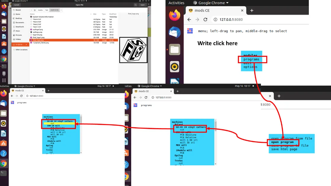
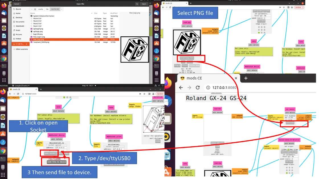
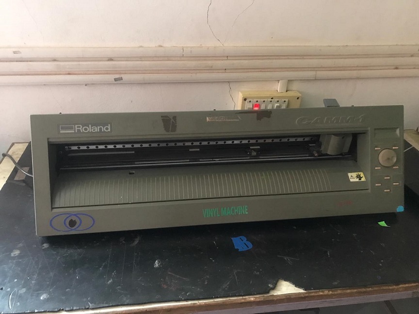
I have designed the logo for my college's Fab Lab, Sanjivani Fab Lab. The logo is designed in the Inkscape software. And Cut using Roland Make CAMM01 vinyl Cutter.

Modsproject- a web-based tool generates the tool path for the vinyl cutting.
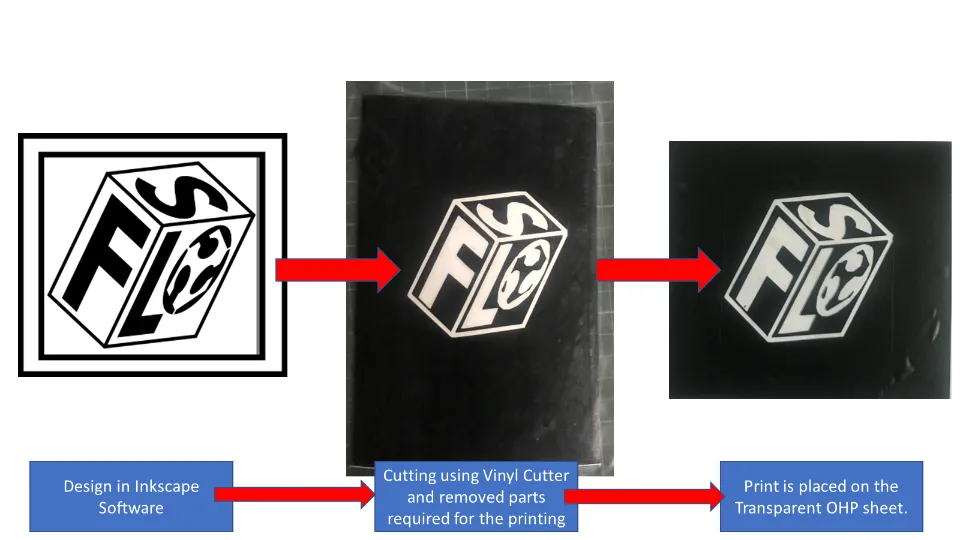
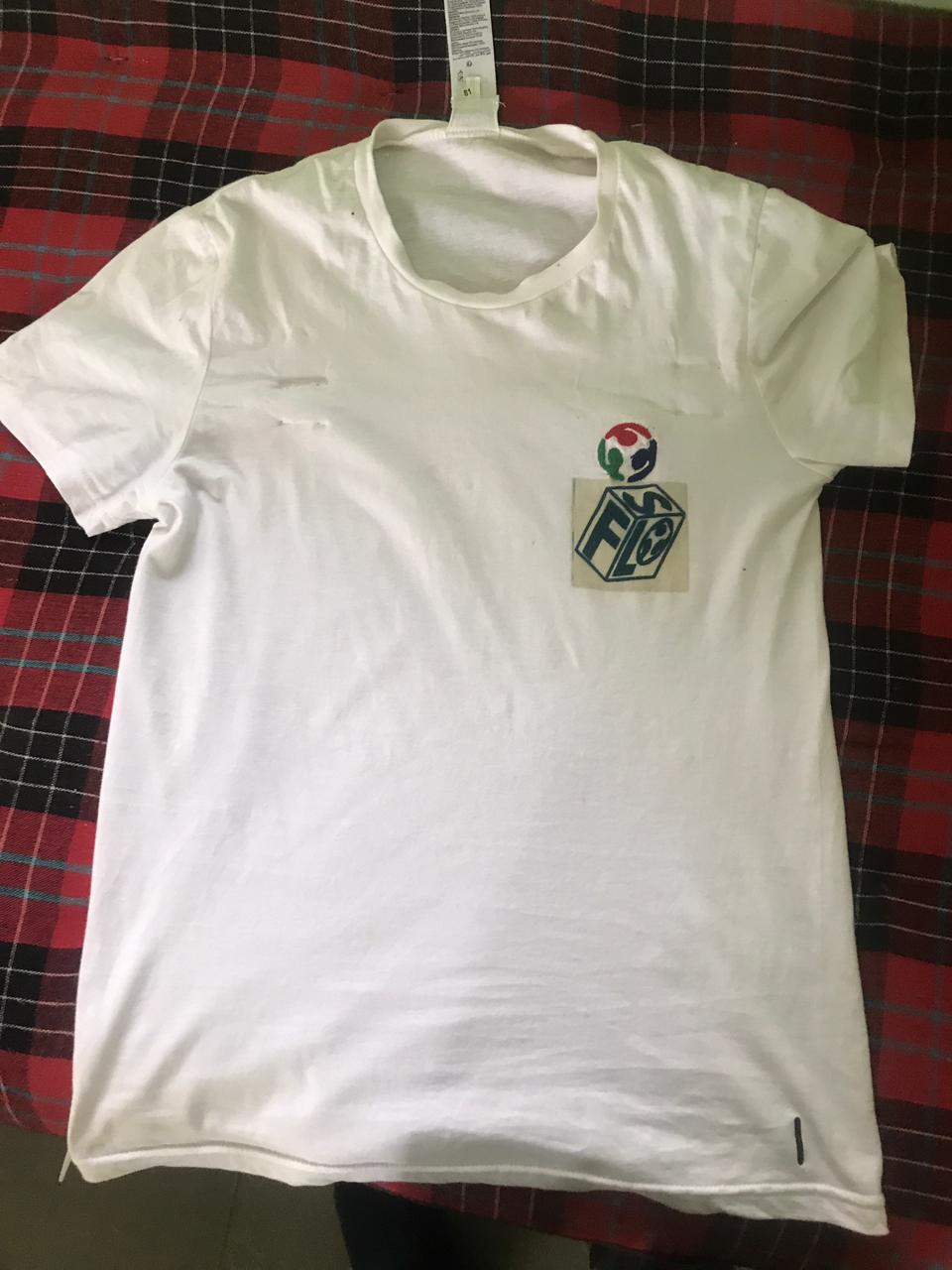
To do a cyanotype print on my T-shirt, I have designed my logo for my college Fab lab, and I
want to print it on my T-shirt. I have cut the logo on the black vinyl paper using the vinyl
cutter.
The part I want to print with blue color removed from the logo and the the remaining part
placed on the transparent OHP paper sheet.
Then I took a T-Shirt and placed acrylic sheet into it to separate the front and back
fabric. I also Additionally added an OHP sheet below the front fabric. Then I Made the marking
on the T-shirt by placing a vinyl cut template. Then the paper tape is placed on the border to
avoid the spread of the print solution on the other areas.
Then I spread the solution on the defined area with the brush.Three/ four layers of solution
were applied to the fabric and then Allowed to dry for one hour in the Black room.
Then Vinyl cut template was placed on the spread area, and it was fixed to the shirt with
the paper tape.
Then T-shirt is placed in the exposed sunlight for about 15 minutes; Then, it is placed in
the tray to clean up the remaining solution. After Cleaning up, the logo looked prettier on the
T-shirt.
.webp)
Again shirt is submerged in the water. And some drops of Hydrogen peroxide are added to the
water to extra glow the print. Hydrogen peroxide boosts the oxidation and adds an extra glow to
the print.
Then T-shirt I allowed drying for an hour. Now it is ready to wear.
I am feeling very happy after completing this assignment.
It feels like doing my absolute best.
I want to thank my friend Mr. Ashish for helping to complete this assignment throughout.
Tray Making for Dome Dryer using Plasma Cutting Machine
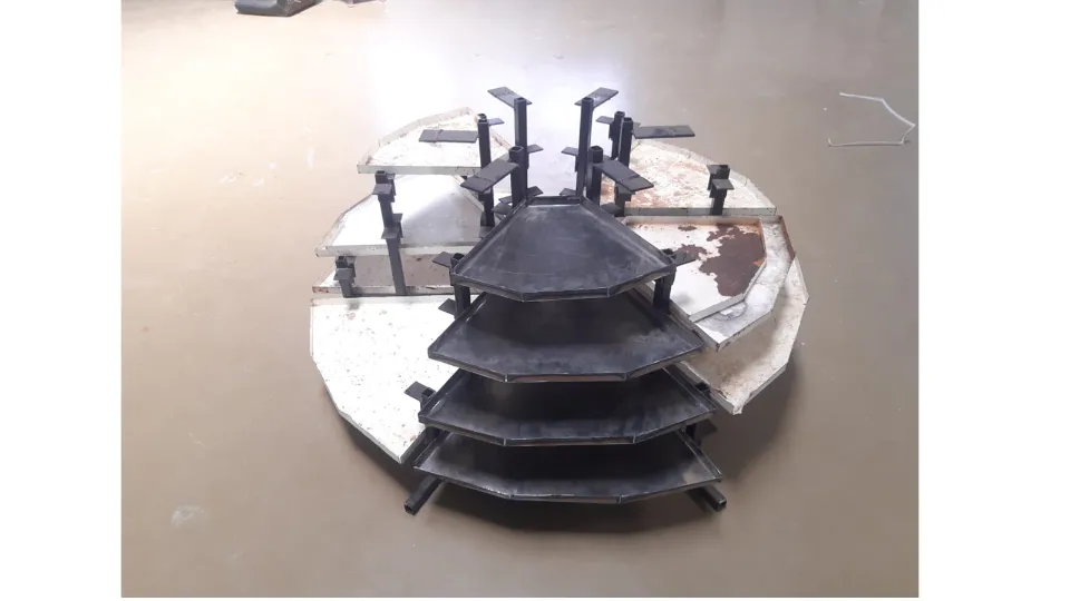
This week in Vigyan Ashram, they have the requirement of the tray making for the Solar-based Dome dryer. They have a requirement of some missing trays in the dryer. They don't dave the Design of the trays. So I have decided to take the dimensions of the trays we Want to add to the dryer. In dome dyer, four steps of trays were placed one above along the Racks in layers. Trays in each layer have exact dimensions. I measured the dimensions with the scale and started to draw the model in Solidworks software.
Design of trays using Solidworks Software.
After taking exact dimensions, I started modeling using Solidworks software.I have drawn the basic sketch in the top plane in the sketch feature of the solidworks. Then used base flange feature to give thickness to the sheet.
.webp)
.webp)
Then I used the flange feature to add flanges to the part shown below.
.webp)
.webp)
For the cutting operation we need to flatten the job. Here I have used unfold feature to flatten the job.
.webp)
.webp)
After developing the flat model, the model is converted into the .dxf file to generate the tool path.
.webp)
Same process was followed for all the four types of the trays. and converted flattened files in to .dxf file format for thr toolpath generation.
Tool Path Generation using FastCam Software
After Generating the .dxf file, I used FastCAM software to generate the
toolpath. This software generates a toolpath in the form of a .gcode.
FastCAM® is a CAD-CAM Software used for Plasma, Oxy, Laser, and Waterjet cutting to provide a
complete NC solution for metal shape nesting and cutting that allows to Draw, Path, Nest, and
Cut all from one system. FastCAM® enables shop floor personnel to begin profile cutting with
minimal training. The FastCAM® System was created to draw, nest, and cut metal as quickly as
feasible. The software's ease of use is just as vital as its superior material utilization and
optimization levels. FastCAM® is less expensive and less complicated than competing systems. The
system is quickly productive because of easy editing and verification of geometry and one-step
nesting. (Wikipedia)
Fast can generate G code for CNC cutting machines. For this software, we need to import the .dxf
file.
Tray model has drawn in the Solidworks software and exported into the .dxf file. This
file is imported into the Fastcam software.
Procedure to generate toolpath using FastCAM shown below.
This is the graphical user interface of the FastCAMM software.
.webp)
To import the the .dxf file click on Main Menu-DXF Restore-(New window will popup)-Select metric unit and -click on Cad Fix and Cad clean and click Enter and select the .dxf file to generate the toolpath.
.webp)
.dxf file will be appeared on the screen
.webp)
To generate the toolpath, click on Men Menu- Program Path-FastPath-Start FastPATH-output NC code and click Yes. This will create .text file in the designated folder.
.webp)
Then software will ask to select start point, from where machine is supposed to star t the cutting operation. After selecting start point, software will generate the .gcode. and the press Ctrl+S to save the file.
.webp)
In the same manner I have generated the tool path for all four tray models shown below.
.webp)
Cutting operation using Plasma cutting machine
Plasma cutting is a procedure that uses an accelerated stream of hot
plasma to cut through electrically conducting materials. Steel, stainless steel, aluminum,
brass, copper, and other conductive metals are common materials that can be cut with a plasma
torch. Manufacturing, vehicle repair and restoration, industrial building, salvage, and
scrapping all use plasma cutting. Plasma cutting is widely used in major industrial CNC
applications to small hobby enterprises. Cutting using plasma - Plasma cutting is made possible
by a conductive gas temperature of up to 30,000°C.
The primary operation of plasma cutting and welding is to establish an electrical channel of
superheated, electrically ionized gas – i.e., plasma – from the plasma cutter to the workpiece,
then back to the plasma cutter through an earth terminal. A compressed gas (oxygen, air, inert
gas, and others, depending on the material to be cut) is blown at high speed through a focussed
nozzle onto the workpiece. An arc forms within the gas between an electrode near the gas nozzle
and the workpiece. Part of the gas is ionized, resulting in an electrically conductive plasma
channel. As the current from the plasma cutter's cutting flame passes through this plasma, it
generates enough heat to melt the workpiece. At the same time, much of the high-speed plasma and
compressed gas blows the hot molten metal away from the workpiece, separating it. Plasma cutting
is a powerful tool for cutting both thin and thick materials. Hand torches can typically cut
steel sheets up to 38 mm thick, while more powerful computer-controlled torches may cut steel
sheets up to 150 mm thick. Plasma cutters are ideal for cutting and welding sheets in curved or
angled shapes because they produce an extremely hot and localized "cone" for cutting.
Machine Specifications:
• Make: Steel Tailor
• Type::SMART III
• Input voltage::110/220 V
• Input Frequency::60/50 Hz
• Input power::200 W
• Controller::LCD 7 ˝ color screen controller
• Effective cutting range::1500 (crosswise) X 3000 (lengthways) mm
• Max cutting speed::4000 mm / min
• Max running speed:: 5000 mm / min
• Machine positional accuracy:: 0.2 mm
• Repeated positioning accuracy :: 0.2 mm
• Cutting thickness:: Plasma cutting: depends on plasma power
• Cutting mode::Plasma
• Cutting software::FastCAM
Important Parameters which affecting Plasma Cutting
1. Kerf: The width of material removed during the plasma cutting process (perpendicular to the
torch and cut axis). Three key factors influence kerf.
2. Cutting Speed: With all other factors held constant, faster cutting rates result in a
narrower kerf. The kerf will continue to narrow until there is no longer any penetration. Slower
travel speeds cause the kerf to widen until the arc is lost.
3. Cutting Amperage: A wider kerf can increase cutting Amperage while keeping the other two
variables constant. Increasing the current will expand the kerf until the nozzle is damaged.
Lowering the Amperage causes the kerf to widen and the cut angle to become more positive until
penetration is lost.
4. Standoff: After piercing, the space between the torch and the workpiece is maintained
(while cutting). Arc voltage feedback is used in most modern systems. Increasing the arc voltage
widens the kerf and increases the standoff distance. The increasing standoff will finally result
in the loss of cut.
All the g.code files generated from the FastCAM software are saved on a USB drive. And USB drive is connected to the Control panel of the Plasma cutting machine.
.webp)
.webp)
.webp)
.webp)
.webp)
.webp)
.webp)
Video of Plasma cutting operation is shown below.
All the four tray parts are cut by using same procedure.
.webp)
Connect USB to the Control Panel of the Plasma cutting machine. Select
the file and click on copy
Click Escape -Click on Auto.
Then click on view.
Click on manual and adjust the plasma head to the desired position
Then click on X for the trial
start the trial by clicking Green Start button.
Adjust the position to set work zero position.
Click the Page down to set its position zero at the top of the workpiece material.
Here we have taken 0.8mm material for the tray.
Then click on the X to disable the trial mode and click on the start button to start the
cutting.
We have given high current by mistake because this edged shows more bur. We post-process it
with a grinder to remove the extra material to remove the bur.
Then we bent all the trays with the help of the vice and the mallet.
After cutting all the parts, they were removed from the machine bend after cooling them down. In Plasma cutting, parts shows some bur, to remove it, I have cleaned the edges with grinder for the best finished part.
Bending operation
After finishing the parts, bending lines were drawn onto it. And with the help of the Bench vice and the mallet, I have bent all the parts as per the required size.
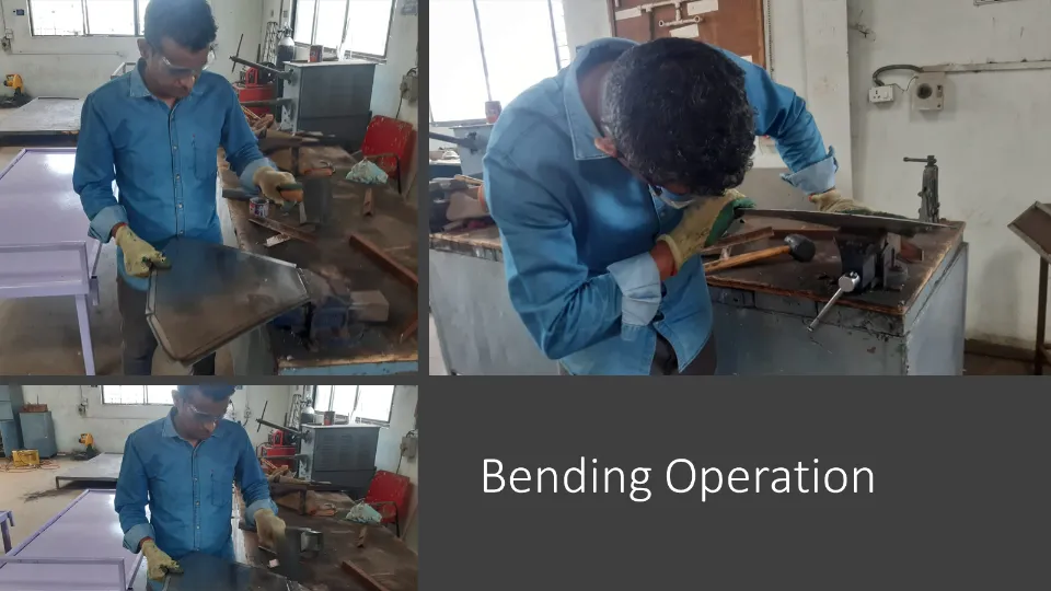
To check whether all trays are bent perfectly, all are placed on the racks of the dome dryer. And all the trays perfectly fit into the dryer.
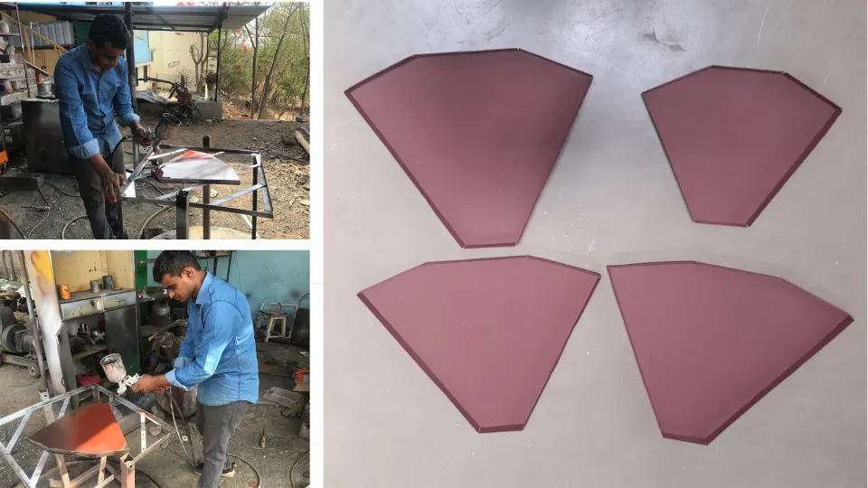
Then all the trays have sprayed with red oxide to avoid the rusting of the sheet metal.
Finally I have completed this assignment. Thank you.
Downloads