Networking and communications
Individual assignment:
Design, build, and connect wired or wireless node(s) with network or bus addresses
Group assignment:
Send a message between two projects
Introduction
This week's assignment is about networking and communication. Last week, I developed my Project
board with ESP32 IC. I have decided to use the same board for networking and communication for
this week.
This week, I want to connect my raspberry pi with my esp board and do the communication between
them.
I purchased Raspberry Pi (Rpi) a long back, and my son uses it to play the games. I have
decided to do something with Rpi. Last year my students used the same RPi for the Augmented
reality-based project and Rover. But I have never tried to do this. I want to explore this week.
By referring to their project, I was sure that communication between esp32 and the raspberry pi
is possible. So I have interacted with my favorite student Mr. Kunal for the communication
between esp32 and the RPI. He helped me throughout the assignment. I found some references on
Randomnerd regarding this assignment and started exploring it. Due to my college work, I was
delayed in completing this assignment this week.
Raspberry will act as a server in this project, and my esp32 board will act as the client. The
client can send and receive data from the server MQTT messaging protocol. Both will communicate
with other through the wifi. And the raspberry pi will send data over a web server either on the
same network or on other networks. Ref:RandomNerdTutorials
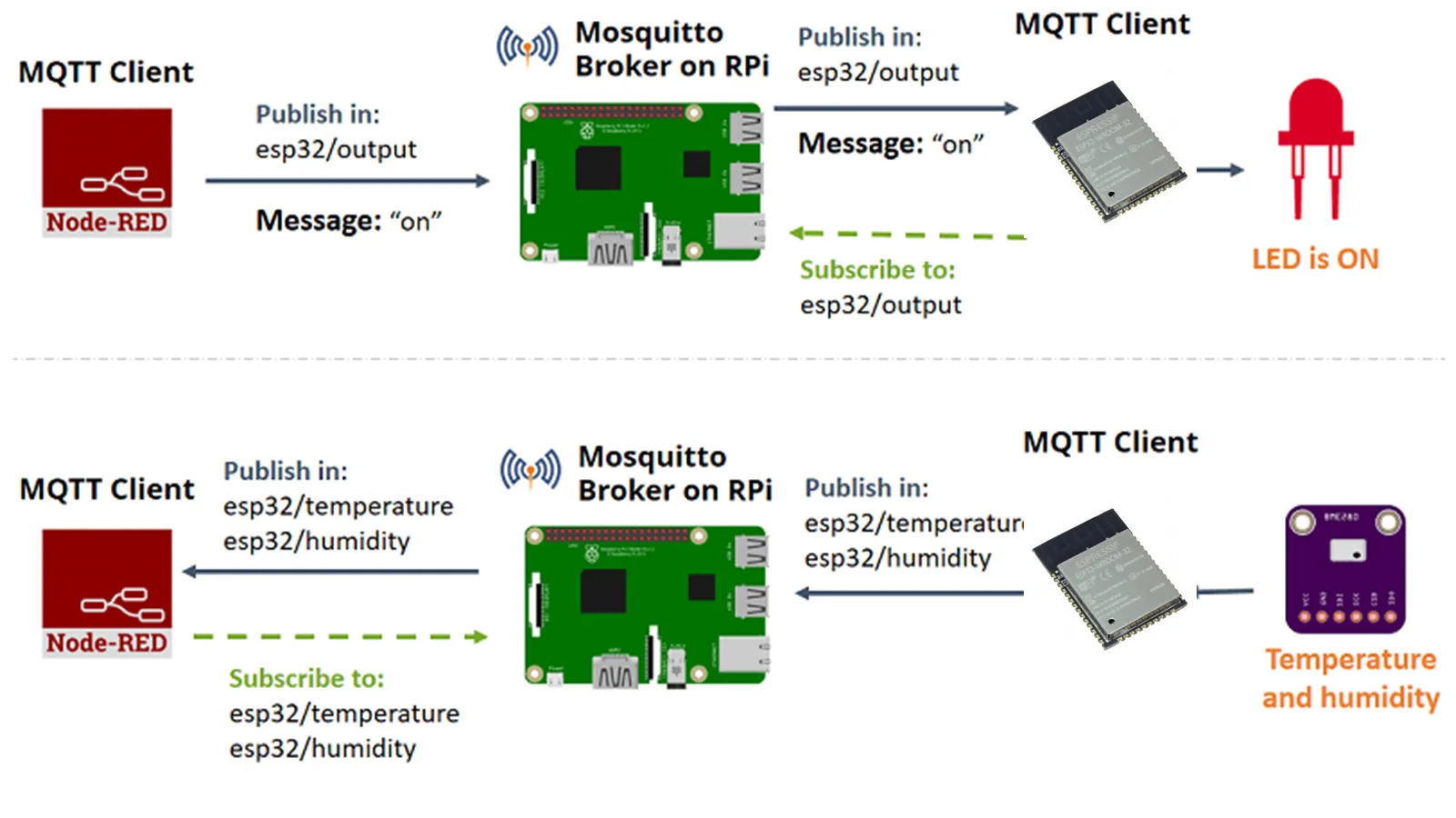
This Assignment is about setup a Node-RED application that controls ESP32 outputs and receives
sensor readings from the ESP32 using the MQTT communication protocol. The Node-RED application is
running on a Raspberry Pi.
The Node-RED application publishes messages (“on” or “off“) in the topic esp32/output. The ESP32
is subscribed to that topic. So, it receives the message with “on” or “off” to turn the LED on or
off.
The ESP32 publishes temperature on the esp32/temperature topic, the humidity on the
esp32/humidity topic, the esp32/altitude topic and the esp32/pressure topic. The Node-RED
application is subscribed to those topics. So, it receives temperature, humidity, pressure and
altitude readings that can be displayed on a chart or gauge.
I have decided to use the MQTT protocol to communicate or send/receive the data between Rpi and my project board. I have referred Beginners Guide To The MQTT Protocol to know about MQTT.
MQTT
MQTT (Message Queuing Telemetry Transport) is a lightweight messaging protocol developed for low-bandwidth devices. As a result, it's the ideal method for transferring data between various IoT devices. MQTT communication is based on a publish-subscribe model. Devices send out signals about a given topic. The message is sent to all devices that have subscribed to that topic. For the communication, we need to install the MQTT broker on the RPi. MQTT broker receives the message from the devices, filters them, and publishes the messages to the subscribed clients.
MQTT Broker
In this case, ESP 32 sends sensor data messages; we require one broker which will receive them and filter messages to send the data to Rpi, Arduino, or any other devices and publish them. It just acts as a post office.
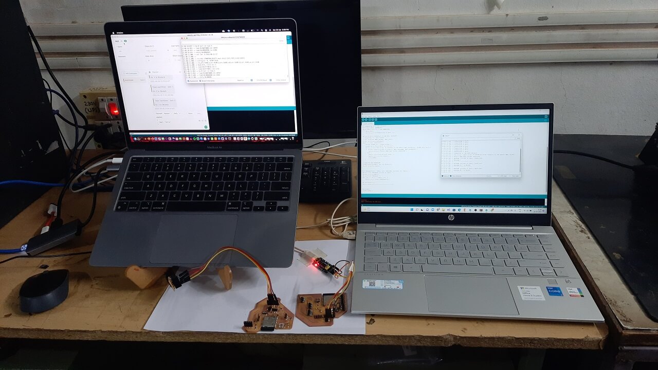
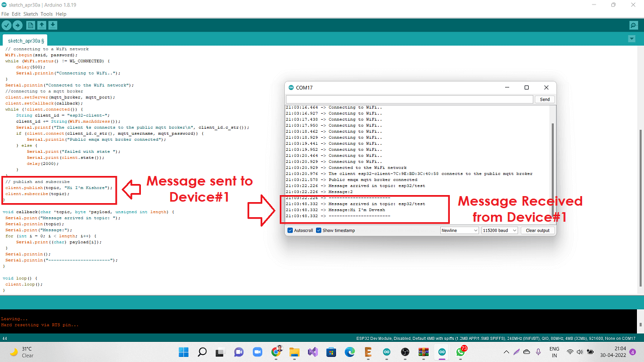
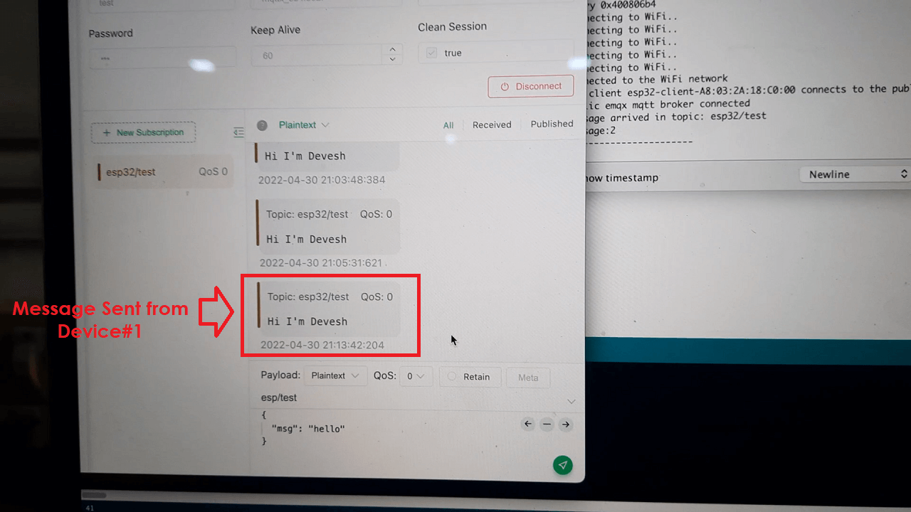
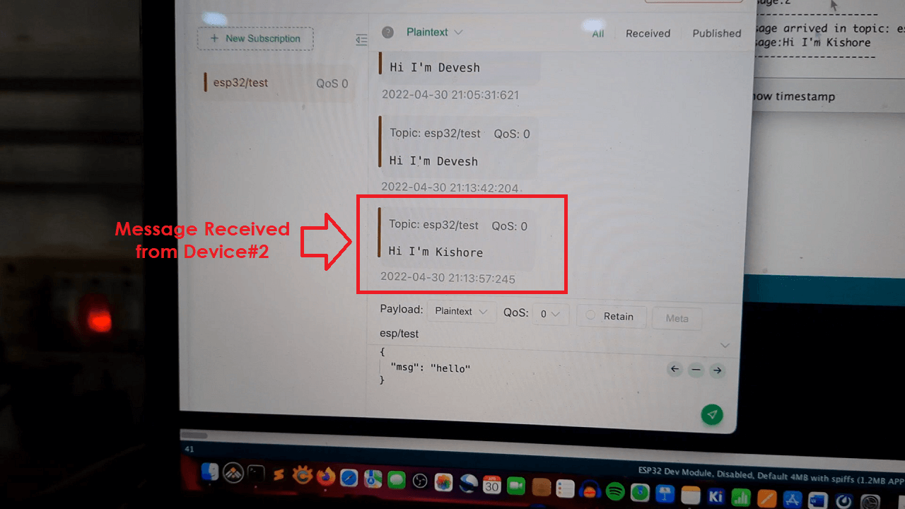
Group Assignment
This assignment is about documenting what we learned during Networking and Communication Week, such as different communication protocols, network kinds, and communication between two boards by sending a message between two projects.Also We have done communication between our board and the Raspberry pi using MQTT. We established communication between two of our project boards with ESP32-Wroom microcontrollers for this group assignment and were able to transmit messages between the boards, as shown below.
I have chosen Mosquito for the MQTT. Installation of Mosquito broker on Raspberry pi shown below.
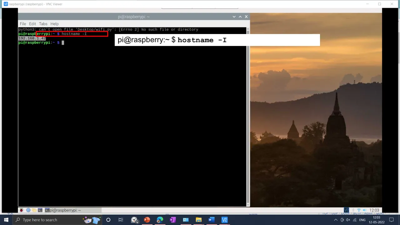
10) The we need to reboot RPi using sudo reboot command for changes to take effect. After rebooting, open the terminal and type hostname -I to get IP address of the RPi.
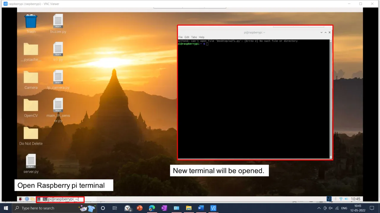
1) Open Raspberry pi terminal.
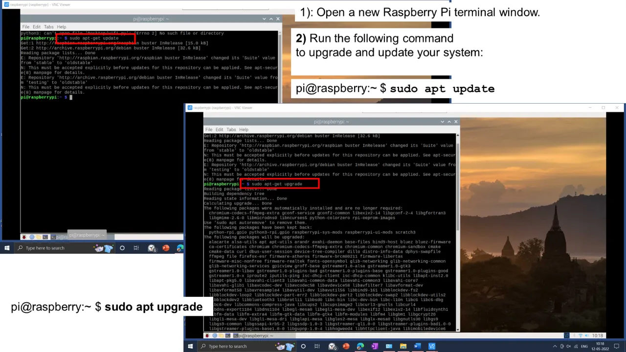
2) Run the sudo apt update to update and sudo apt upgrade to upgrade the raspberry pi.
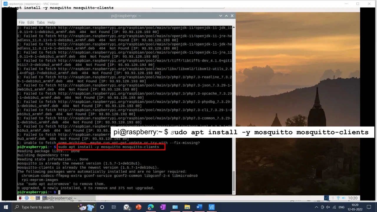
3) install the Mosquitto Broker using command : sudo apt install -y mosquitto mosquitto-clients
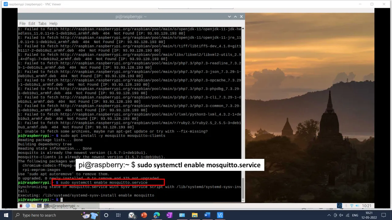
4) To make Mosquitto auto start when the Raspberry Pi boots, using sudo systemctl enable mosquitto.service
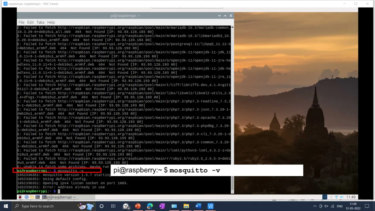
5) Now, test the installation by running the following command: mosquitto -v This returns the Mosquitto version that is currently running in your Raspberry Pi. It means mosquito broker is installed on the Rpi.
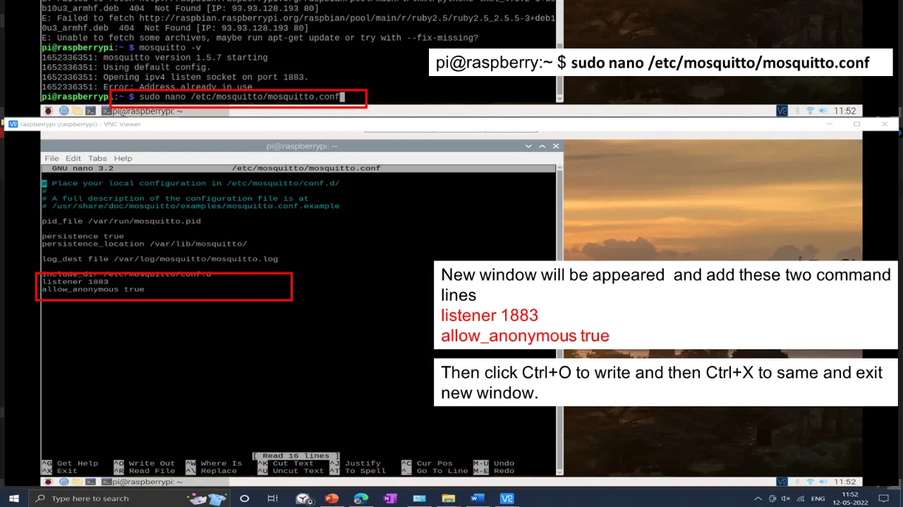
6) to open the mosquitto.conf file use following command
sudo nano /etc/mosquitto/mosquitto.conf this will open new terminal window and
listener 1883
allow_anonymous true
lines in the configuration window and click Ctrl+O and Ctrl+X to clase the configuration
window.
The we need to reboot RPi using sudo reboot command for changes to take effect.
After rebooting, open the terminal and type hostname -I to get IP address of the
RPi.
This id require for the arduino programming and for local hosting of the web server. My Rpi
Ip address is 192.168.1.42
Node-red Setup
Node-RED includes a browser-based flow editor that makes it simple to connect flows using the palette's many nodes. In a single click, flows can be pushed to the runtime. A rich text editor can generate JavaScript functions within the editor. A built-in library lets you save and reuse valuable functions, templates, and flows.
Node-RED includes a browser-based flow editor that makes it simple to connect flows using the
palette's many nodes. In a single click, flows can be pushed to the runtime.
A rich text editor can generate JavaScript functions within the editor.
A built-in library lets you save and reuse valuable functions, templates, and flows.
I have referred Randomnerd
documentation and Dr.
Jali Laru’s documentation to set up the node-red on raspberry pi.
Node-red in built installed in the Raspberry pi os. Or one can install it node-red on by
raspberry pi by running the following command.
bash <(curl -sL
https://raw.githubusercontent.com/node-red/linux-installers/master/deb/update-nodejs-and-nodered)
Then I have run the following command to set up automatic Run of Node-run when
pi boots up.
sudo systemctl enable nodered.service
Then I have restart the pi.
sudo reboot
To run the node red on the browser we need to enter in th
http://YOUR_RPi_IP_ADDRESS:1880 in the browser in my case it was
In my case is: http://192.168.1.42:1880
.webp)
.webp)
.webp)
.webp)
.webp)
.webp)
.webp)
.webp)
.webp)
.webp)
Microcontroller and the Arduino Ide:
After setting up Raspberry Pi as a server, MQTT broker, and Node-Red, I have to set up the
Arduino Ide and the microcontroller connections.
Here I am using the BMP280 sensor to measure temperature, pressure, Humidity, and altitude
and Led to control it from the node-red.
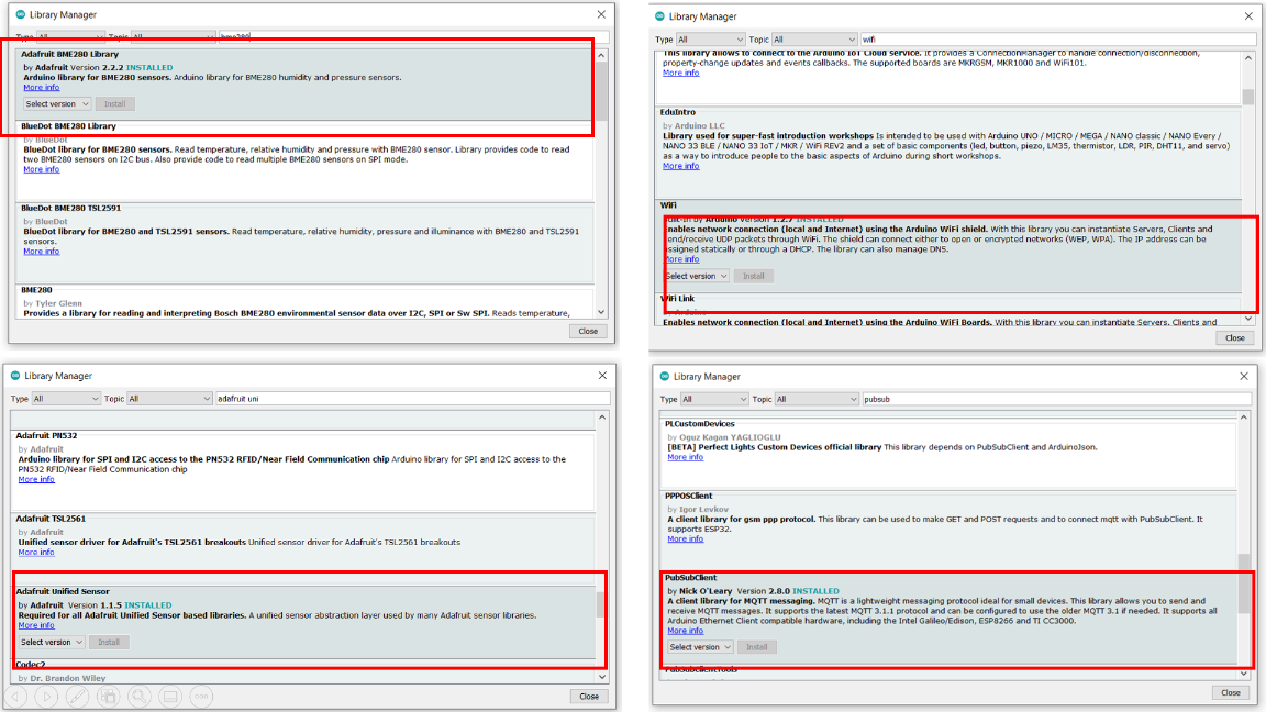
I am using Arduino IDE for the programming of my project board. I have added the following
libraries to the Arduino to use wifi, BME sensor, and MQTT.
 Then I set up the connections of the BME 280 sensor and LED.
The connection setup is shown below.
Then I set up the connections of the BME 280 sensor and LED.
The connection setup is shown below.
.webp)
BMP sensor is works on the i2c communication. It uses only two bi-directional open-drain
lines for SDA and SCL data communication. Both these lines are pulled high.
Serial Data (SDA) – Transfer of data takes place through this pin.
Serial Clock (SCL) – It carries the clock signal.
In esp 32, GPIO 21 is the default SDA pin, and GPIO 22 default SCl pin. We need to
define SDA and ScL pins for the i2c communication. But on my board, I have not made any
arrangement for them. Burt beuty of ESP32 is that, we can any GPIO pin as a SDC and SCl
pins. You may enable I2C capabilities on practically any pin on the ESP32 by simply setting
it in your code.
Use the Wire.h library to interface with I2C devices using the ESP32 with the Arduino IDE.
You initialize the I2C with this library as follows:
Wire.begin(I2C_SDA, I2C_SCL);
Let’s take a look at the relevant parts to use other I2C pins.
First, define your new I2C pins on the I2C_SDA and I2C_SCL variables. In this case,
we’re using GPIO 33 and GPIO 32.
I have set GPIO 19 and GPIO23 as my SCL and SDA pins respectivly.
#define I2C_SDA 23
#define I2C_SCL 19
Create a new TwoWire instance. In this case, it’s called I2CBME. This creates an I2C
bus.
TwoWire I2CBME = TwoWire(0);
In setup(), initialize the I2C communication with the pins you’ve defined earlier. The
third parameter is the clock frequency.
I2CBME.begin(I2C_SDA, I2C_SCL, 400000);
Finally, initialize a BME280 object with your sensor address and your TwoWire object.
status = bme.begin(0x76, &I2CBME);
Default I2C address for the BME280 is 0x76 entered in the code.
Arduino program for this assignment is shown below.
I have made the connection. Accordingly, pins are defined in the Arduino code, and the code is flashed into the ESP32 board.
Final Output
The final output of the board is shown below.
I have made the connection. Accordingly, pins are defined in the Arduino code, and the code is flashed into the ESP32 board. The final output of the board is shown below.
We need to subscribe to data on the Raspberry pi; we need to add the following
commands on the terminal of the raspberry pi.
To get the pressure
mosquitto_sub -d -t esp32/pressure
To get the Temperature
mosquitto_sub -d -t esp32/temperature
For the Humidity
mosquitto_sub -d -t esp32/humidity
And for the Altitude
mosquitto_sub -d -t esp32/altitude1
To on/off the Led from the raspberry pi, we need to publish a message using the
command
mosquitto_pub -d -t esp32/output -m "on"
mosquitto_pub -d -t esp32/output -m "off"
Following video shows the sensor data on Arduino Serial communication ,Raspberry pi
and the Node-red display.
Group Assignment
Group Assignment Link.
This assignment is about documenting what we learned during Networking and Communication Week, such as different communication protocols, network kinds, and communication between two boards by sending a message between two projects. We established communication between two of our project boards with ESP32-Wroom microcontrollers for this group assignment and were able to transmit messages between the boards, as shown below.
I have used the MQTT protocol to communicate or send/receive the data between Rpi and my project board.
Downloads
Program files
p { color: red }
Checklist
-
Linked to the group assignment page
and reflected what you learned individually of the group assignment.
-
Documented your project.
-
Documented what you have learned from
implementing networking and/or communication protocols.
-
Explained the programming process/es
you used.
-
Outlined problems and how you fixed
them.
-
Included design files (or linked to
where they are located if you are using a board you have designed and
fabricated earlier) and original code.
Linked to the group assignment page and reflected what you learned individually of the group assignment.
Documented your project.
Documented what you have learned from implementing networking and/or communication protocols.
Explained the programming process/es you used.
Outlined problems and how you fixed them.
Included design files (or linked to where they are located if you are using a board you have designed and fabricated earlier) and original code.