Output Devices
Group Assignment:
Group Assignment Link
Measure the power consumption of an output device
Individual assignment::
Add an output device to a microcontroller board you've designed, and program it to do something.
This week is about Output week. I checked the maximum number of available output devices using
the Arduino board and my designed PCB board.
Output device refers to any piece of Electronics hardware that turns data into a
human-readable format. It may be textual, graphical, tactile, audible, or video-based. Monitors
and printers are examples of Visual Display Units (VDU) among the output devices. Motors,
Actuators, LED, Buzzer, etc. are all output devices. Therefore, we need an output device to
display the information as text and images.
This week, I designed the board for the output devices. I have designed the board so that I
can connect3 to 4 devices. But Actually, it was my mistake; I was supposed to design the board
to connect one or two devices effectively. I have decided to use the ATTiny44 microcontroller
for the PCB board.
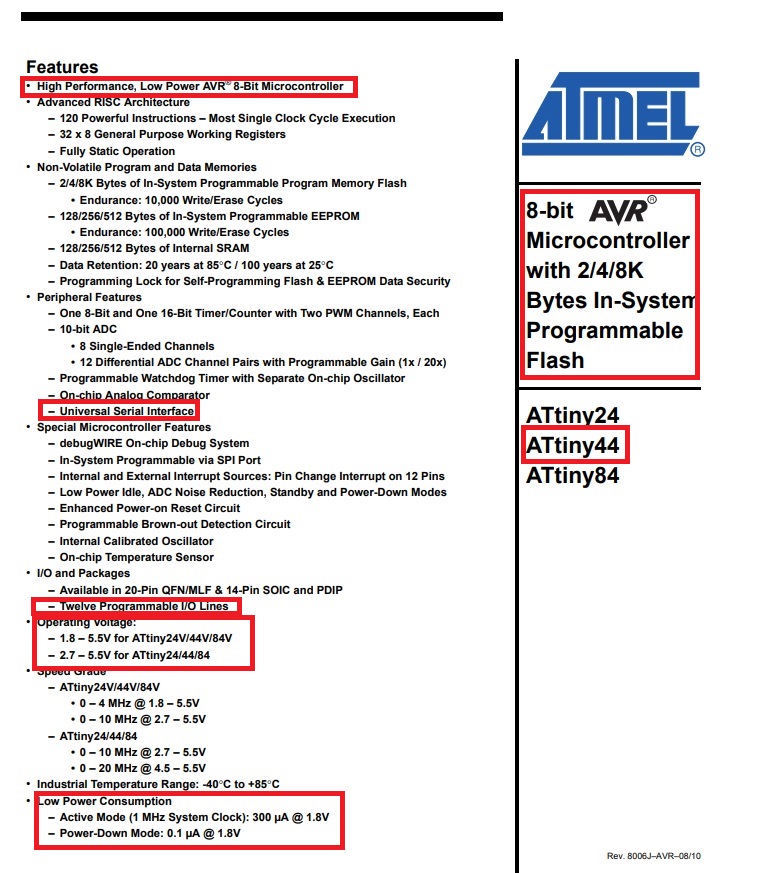
Datasheet Attiny 44
A datasheet, also known as a spec sheet, is a document that specifies the performance and other
attributes of a product, machine, component, material, subsystem, or software in precise detail for
a buyer to understand the product and a technical expert to understand the component's role in the
overall system.Ref: Wikipedia
Then I have searched online about the Datasheet of ATtiny 44. I found the Datasheet on
following Website
While selecting the microprocessor, we need to see about Power requirement, no. of Input-output
pins, no. of bits, Pinout, Cache, In-system Programmer EEROM etc.
The pinout is the assignment of the functions of the pins in various connectors, or in radio-electronic components such as microcircuits, transistors, relays, according to their reference numbering.
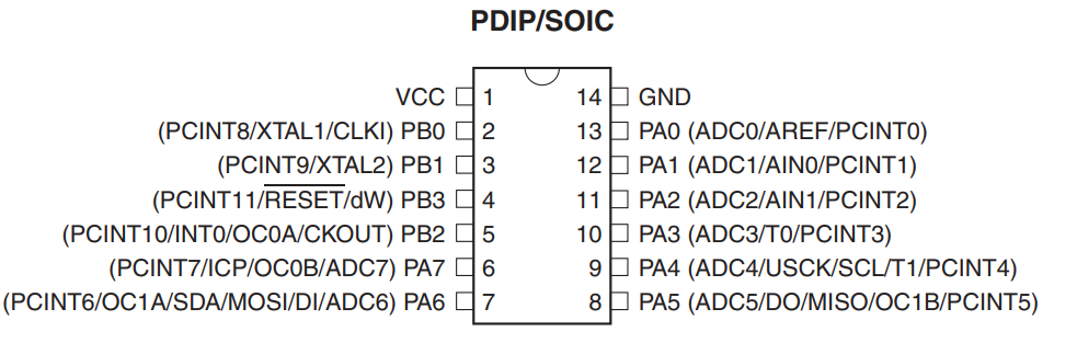
Pin Functions
VCC Supply voltage.
GNDGround.
Port B (PB3:PB0)
Port B is a 4-bit bi-directional I/O port with internal pull-up resistors (selected for each bit).
The
Port B output buffers have symmetrical drive characteristics with both high sink and source
capability except PB3 which has the RESET capability. To use pin PB3 as an I/O pin, instead of
RESET pin, program (‘0’) RSTDISBL fuse. As inputs, Port B pins that are externally pulled low
will source current if the pull-up resistors are activated. The Port B pins are tri-stated when a
reset condition becomes active, even if the clock is not running.
RESET
Reset input. A low level on this pin for longer than the minimum pulse length will generate a
reset, even if the clock is not running and provided the reset pin has not been disabled. Shorter
pulses are not guaranteed to generate a reset.
The reset pin can also be used as a (weak) I/O pin.
Port A (PA7:PA0)
Port A is a 8-bit bi-directional I/O port with internal pull-up resistors (selected for each bit).
The
Port A output buffers have symmetrical drive characteristics with both high sink and source
capability. As inputs, Port A pins that are externally pulled low will source current if the pull-up
resistors are activated. The Port A pins are tri-stated when a reset condition becomes active,
even if the clock is not running. Port A has alternate functions as analog inputs for the ADC,
analog comparator, timer/counter.
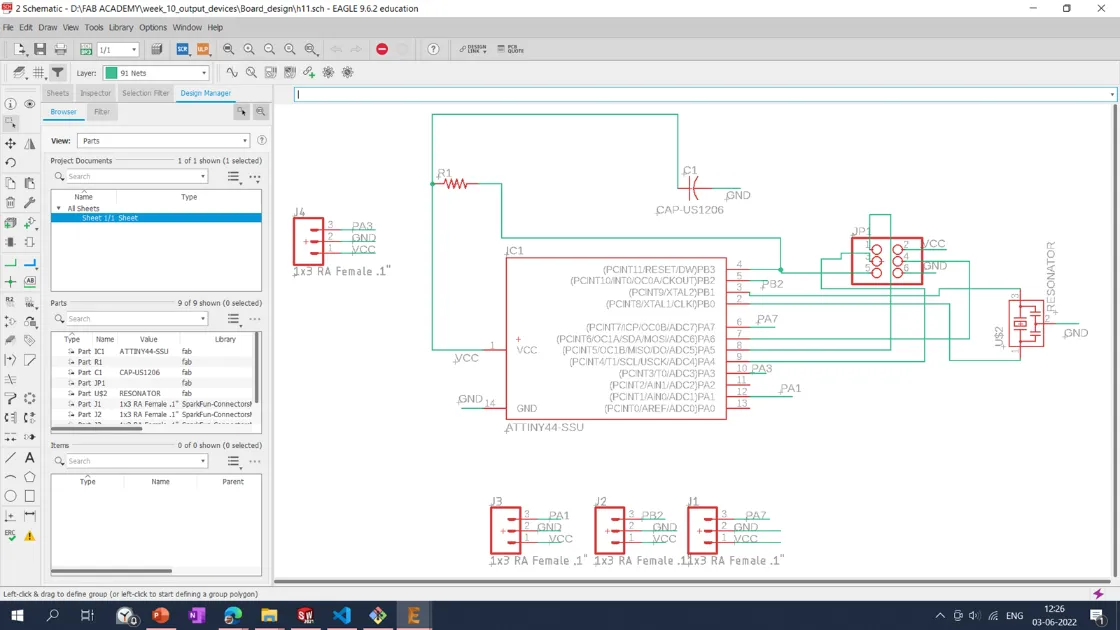
PCB Design
For this week, I have decided to develop a PCB for output devices; I have connected, designed,
machined, and developed the board to connect four output devices.
I have designed the output board by referring to my Hello Board design. In which I have used
Attiny44 microcontroller. I have used Autodesk Eagle to design the PCB. Then it is exported into the
.PNG file for the Machining.
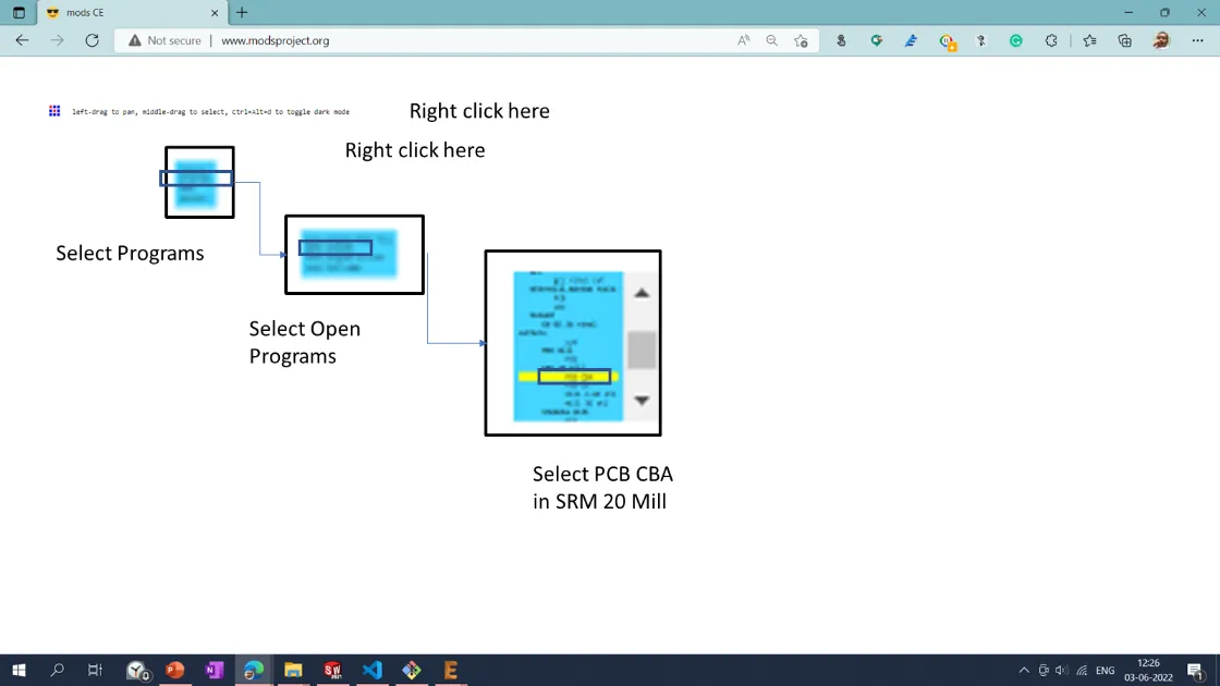
The modsproject tool is used to generate the toolpath for the PCB milling.
An SRM20 PCB milling machine is used to machine the PCB.
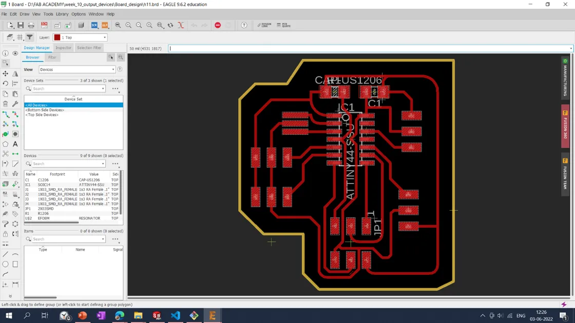

I exported the PCB tracing and interior file into the .png file with 1000 dpi resolution and Monochrome color setting by selecting the top and Dimension layer.

Then PNG file is imported into the ModsProject online toolpath generation tool. The following process was followed to generate the toolpath.
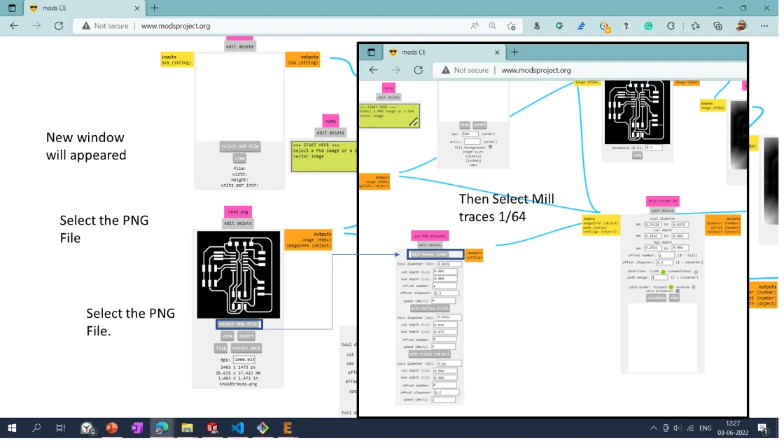
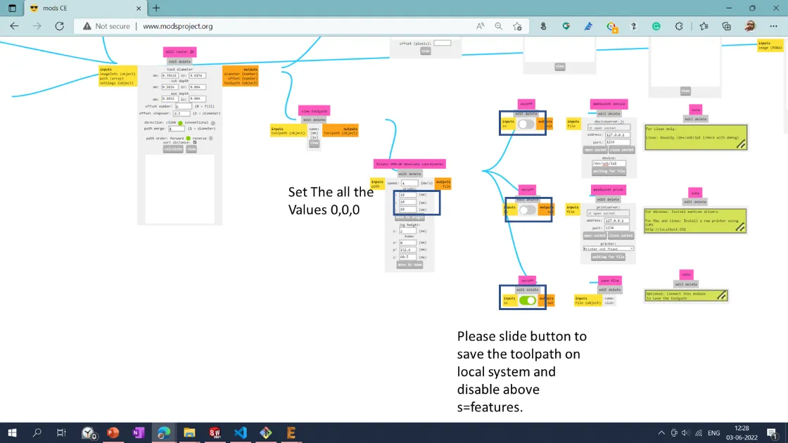
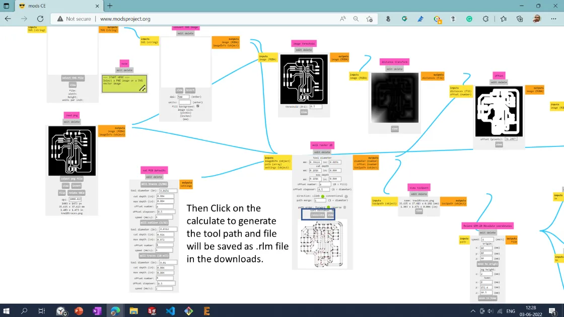
The file is being imported into the SRM20 milling machine for the machining operation. I have used a 1/64" diameter tool for the tracing and a 1/32" diameter for the interior cut. The cutting and tracing of the operation of the PCB are shown below.
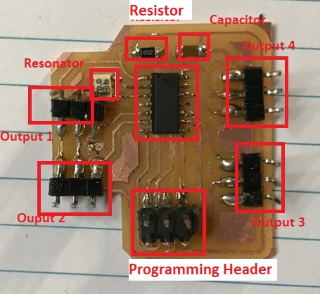
Components Required for the Output board:
1. Resistor: 10K- 1 Qty
2. Capacitor: 1uF- 1 Qty
3. Microprocessor ATtiny44- 1 Qty
4. Resonator: 20MHz- 1 Qty
5. Programming pin header: 2x3- 1 Qty
6. Header pin 4 Qty
The output board with the stuffed components is shown below.
I have referred the following pinout for ATTIny44 programming using Arduino IDE.
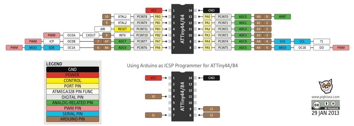
After the soldering operation, I have the test, my output board, attaching the Red LED at port PA1, and uploading the program using Arduino IDE. The program is uploaded, and Led is glowing. Board is functioning well.
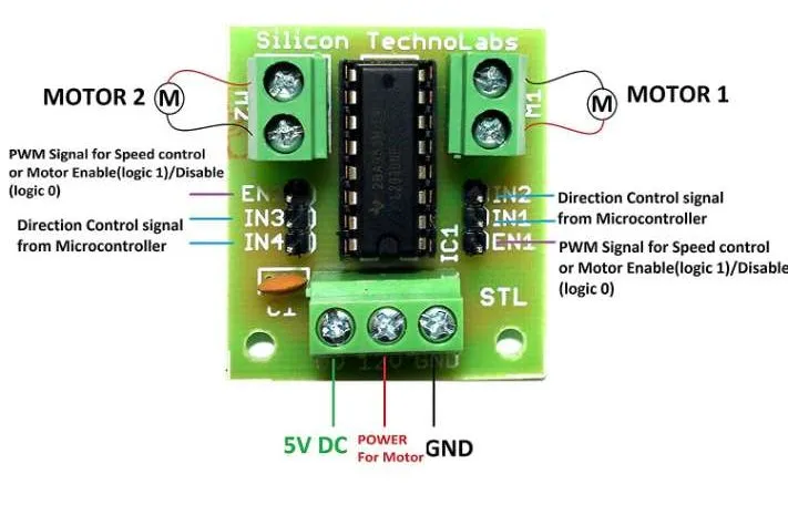
DC Motor
I want to control the DC motor with Arduino. I have used L293D Motor Driver Module to control the
DC motor. With this driver, we can control the Stepper motor also.
The L293D Motor Driver Module is a motor driver with medium power ideal for operating DC Motors
and Stepper Motors. It employs the well-known L293 motor driver IC. It can turn on and off four
DC motors or control the direction and speed of two DC motors.
The driver dramatically simplifies and increases the ease with which microcontrollers may
control motors, relays, etc. It can operate 12V motors with a total DC current of 600mA.
1. Wide supply voltage: 4.5 V to 12 V.
2. Max supply current: 600 mA per motor.
Pinouts of L293D Motor Driver Module
L293D consists of two H-bridge. H-bridge is the simplest circuit for controlling a low current-rated motor. H-bridge is so named because it can be represented by four switches on the letter 'H' corners. The basic H-bridge diagram is shown below:
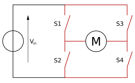
The arrow on the left indicates the greater potential side of the circuit's input voltage in the provided diagram. If the switches S1 and S4 are in the closed position while the switches S2 and S3 are in the open position, the circuit becomes shorted across S1 and S4. This establishes a path for the current to flow, beginning with the V input, switching S1 to the motor, then switching S4, and finally exiting the circuit. This current flow would cause the motor to rotate in one direction. The direction of motion of the motor can be either clockwise or counterclockwise because the rotation of the motor is dependent on the connection of the motor's terminals to the switches. When S3 and S2 are closed, and S1 and S4 are left open, the current flows in the other direction, and the motor will rotate counterclockwise. The 'STALL' state will arise when S1 and S3 are closed while S2 and S4 are open (The motor will break). REF: Robotix:Motor Driver IC
Motor Operation using Driver:
• Pin 7 = Logic 1 and Pin 8 = Logic 0 | Clockwise Direction
• Pin 7 = Logic 0 and Pin 8 = Logic 1 | Anticlockwise Direction
• Pin 7 = Logic 0 and Pin 8 = Logic 0 | Idle [No rotation] [Hi-Impedance state]
• Pin 7 = Logic 1 and Pin 8 = Logic 1 | Idle [No rotation]
Relay
A relay is a switch that is controlled by electricity. Their internal mechanical switching
mechanism is typically operated by an electromagnet (coil) (contacts). An open relay contact
will turn on the power to a circuit when the coil is engaged.
I have used a LOW-Level 5V 2-channel relay interface board with a 15-20mA driver current
required for each channel. It can be utilized to operate a variety of large-current appliances
and equipment. It contains high-current relays that operate at AC250V 10A or DC30V 10A and a
standard interface that may be operated directly by a microcontroller.
This is a two-channel 5V relay module that can control a variety of appliances and other
high-current equipment. Microcontrollers can control it directly (8051, AVR, PIC, DSP, ARM, ARM,
MSP430, TTL logic). 5V 2-Channel Relay Interface Board with 15-20mA Driver Current for each
AC250V 10A high-current relay; DC30V 10A high-current relay Microcontroller can control the
standard interface directly (8051, AVR, PIC, DSP, ARM, ARM, MSP430, TTL logic) Relay output
condition is indicated by LEDs. I have used 2 channel relay available in our lab.
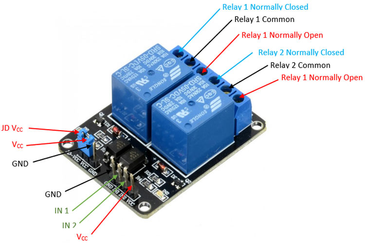
The relay has one NC (nomalclose), one NO (nomalopen), and one COM submodular (Common). The
channel relay has two NCs, two NOs, and two COMs. The normal close port contact and state
without power are denoted by NC, while No denotes the normal open port contact and state with
power. The common port is abbreviated as COM. Depending on whether there is electricity, you can
choose between NC and NO ports. Pinout of a relay is shown below.
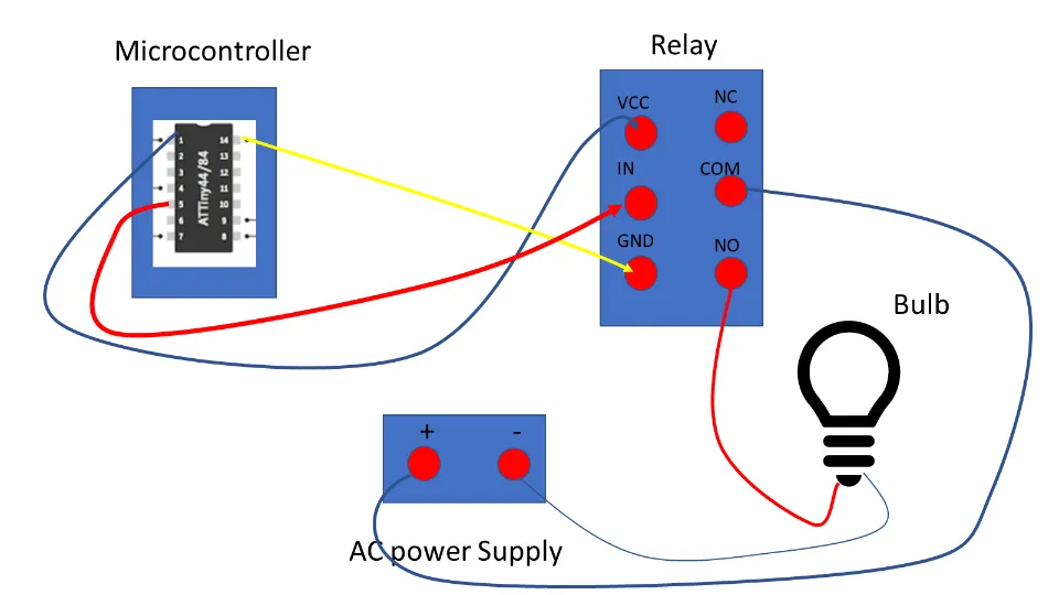
I have decided to attach a relay to the ON/OFF 6-watt LED bulb for the second output and then connected PA5 Pin to the relay NO (normally open Pin) and PA1 to LED. A detailed connection diagram is shown below.
The program written for operating the relay shown below.
The final Bulb ON/OFF trial using a relay is shown below.
Group Assignment:
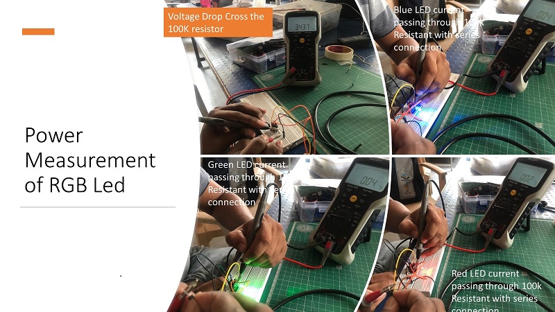
In group assignment we have to measure power of output device.So we decided to measure power consumption of RGB Led. We want to measure the power requirement to glow each color of RGB LED.
We have connected the LED to our Output devices board and programmed the PCB to glow with Red, Blue, and Green colors to measure the voltage across the pin connection. Also measured the current by attaching the resistance of 100K in series with the help of Megger make multimeter.
\
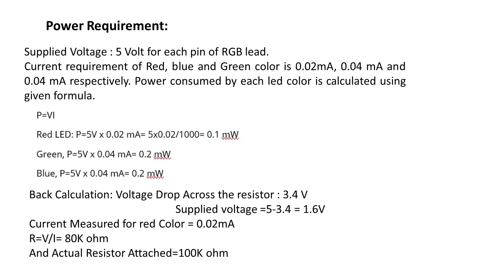
These calculations will be helpful for the total power requirement of the Final Project for the selection Battery.
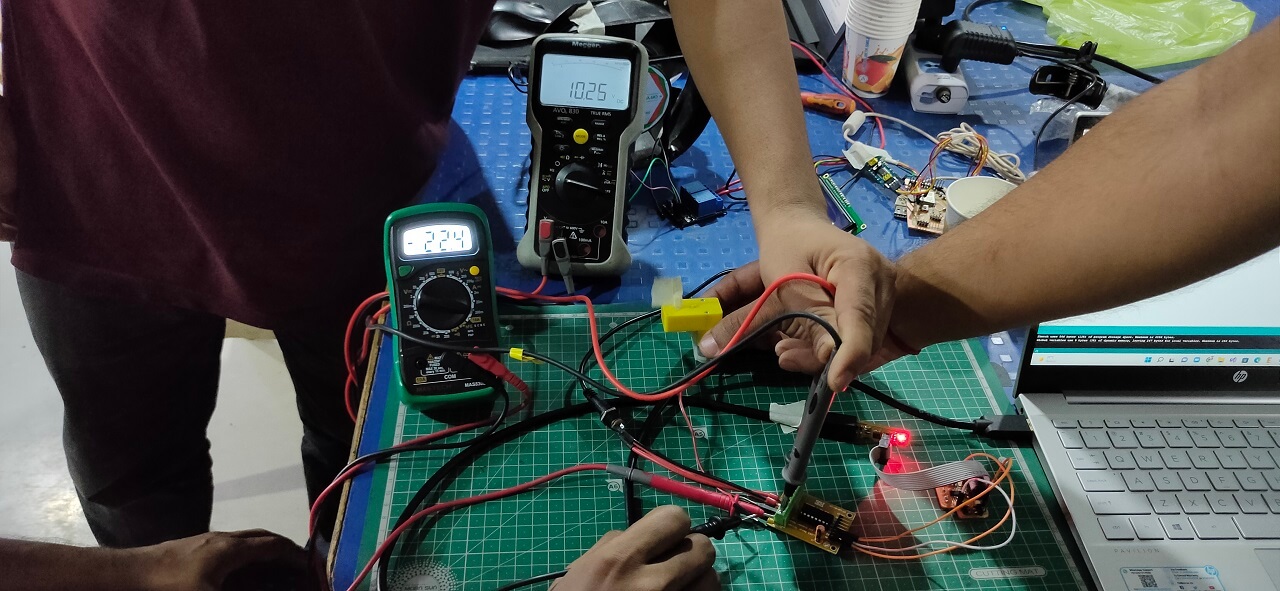
After programming the board using Arduino IDE, we connected the DC motor to the output device board and started the motor. First, we measured the series current and the voltage across the parallel connection, as shown below.
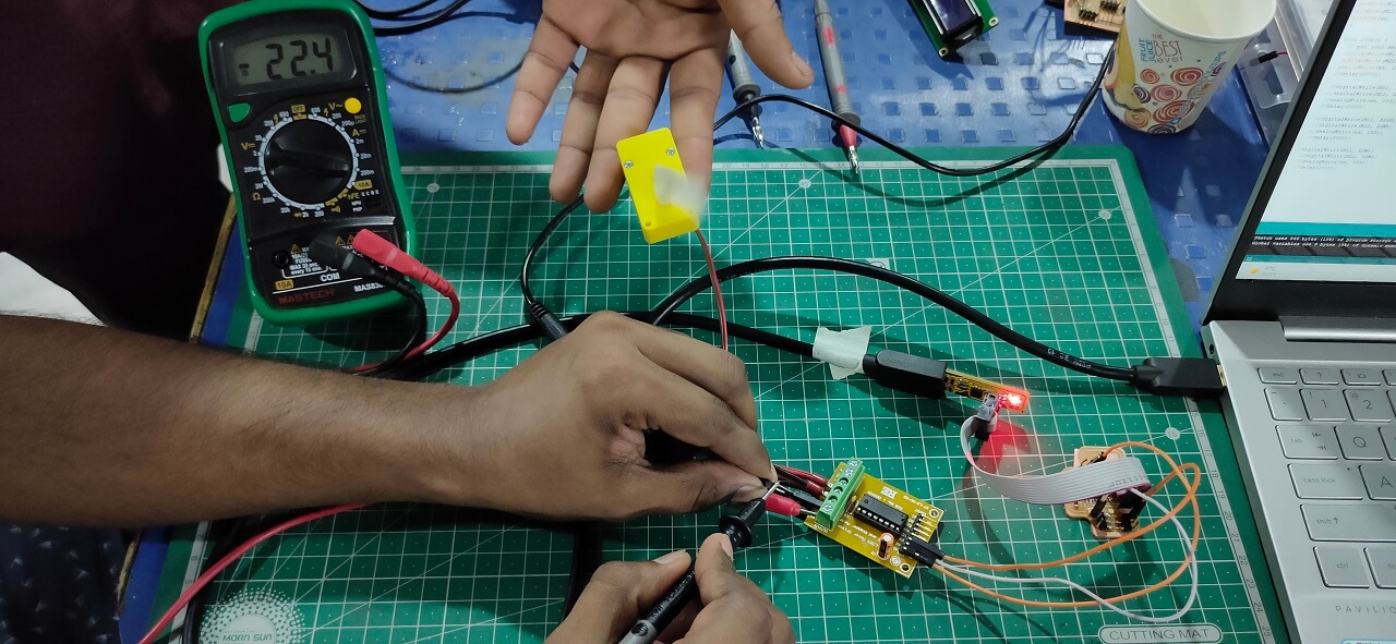
Power consumption of a DC motor: The observed DC motor voltage (V) was 10.25 Volts, and the required current value (I) varied. However, the most steady current was 22.4 mA. Therefore, the power consumption of a DC toy motor is equal to P = V x I = 10.25 x 0.0224 A = 0.2296 Watts.
Downloads
Program files
LCD File .
Checklist
-
Linked to the group assignment page
-
Documented how you determined power consumption
of an output device with your group
-
Documented what you learned from interfacing
output device(s) to microcontroller and controlling the device(s)
-
Described your design and fabrication process or
linked to previous examples.
-
Explained the programming process/es you used.
-
Outlined problems and how you fixed them
-
Included original design files and code
-
Included a ‘hero shot/video’ of your board
Linked to the group assignment page
Documented how you determined power consumption of an output device with your group
Documented what you learned from interfacing output device(s) to microcontroller and controlling the device(s)
Described your design and fabrication process or linked to previous examples.
Explained the programming process/es you used.
Outlined problems and how you fixed them
Included original design files and code
Included a ‘hero shot/video’ of your board
Using Arduino Board I tried some Output devices shown below.
RGB LED
LCD- Hello World
LCD- Fab Lab
OLED- Fab Lab
Servo Motor
Stepper Motor