Electronics Design
Task: Electronics Design
• Group assignment:
• Use the test equipment in your lab to observe the operation of a microcontroller circuit board (in
minimum, check operating voltage on the board with multimeter or voltmeter and use oscilloscope to
check noise of operating voltage and interpret a data signal).
• Document your work to the group work page and reflect on your individual page what you learned.
• Individual assignment:
• Redraw one of the echo hello-world boards or something equivalent, add (at least) a button and LED (with current-limiting resistor) or equivalent input and output, check the design rules, make it, test it. Optionally, simulate its operation.
Introduction
This week's assignment is crucial for me. As a mechanical engineer, I have very little knowledge
about Electronics. I need to learn this because I need to effectively teach it to my students. I
tried to understand it a lot of time, but I fear it due to the unavailability of electronics
components and their practical uses. But with the Fab Academy course, to complete the project and
assignments, I need to learn it at any cost. After Wednesday's lecture, Our Instructor, Suhas Sir,
introduced all the essential electronics components required for the assignment and the project.
This assignment is crucial because I will learn about various electronic components, circuit design,
and production.
And I started exploring basic electronics components like resistor, capacitor, LED, etc., and
circuit design software.
Basic Electronics
An electronic circuit consists of several electronic components, such as resistors, transistors,
capacitors, inductors, diodes, etc., that are connected with conductive wires or traces through
which electric current can flow. The electronic circuit must have at least one active component. The
electronic circuit allows various simple and complex operations to be performed:
to amplify signals.
To perform computations.
To move data from one place to another.
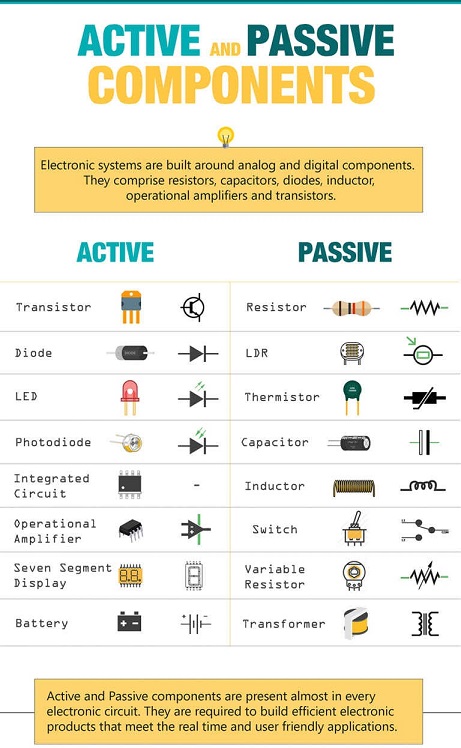
Passive and Active elements:
Electronics systems consist of Passive and Active elements, and I need to learn how to classify
active and passive components and their applications.
Active elements are the devices which need an external trigger source to operate reliably.
Similarly, Passive elements are the devices which don’t require external power sources to operate
and are independent.
Active elements are devices that require an external trigger source to function correctly.
Active components can have the ability to control the voltage and current to direct charge flow
in electronic circuits.
Some Active elements are Diodes, Transistors, voltage-operated devices, Vacuum tubes, voltage,
and current sources.
Passive elements are devices that do not require external power to operate.
A passive component is an electronic component that can only receive energy, either dissipate,
absorb or store it in an electric field or a magnetic field. Passive elements do not need any form
of electrical power to operate.
For Example: Resistor, Capacitor, Inductor etc…
Image Reference
Basic Electronics Components
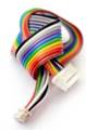
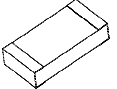
Ribbon Cable
Ribbon cable, also known as multi-wire planar cable, is used for a wide variety of high speed, high performance, space restricted applications, and low voltage applications.
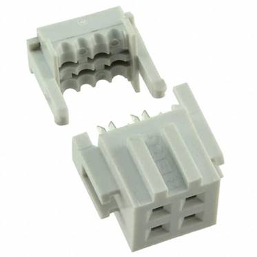
IDC Converter
An insulation-displacement contact (IDC), also known as insulation-piercing contact (IPC), is an electrical connector designed to be connected to the conductor(s) of an insulated cable by a connection process which forces a selectively sharpened blade or blades through the insulation, bypassing the need to strip the conductors of insulation before connecting.
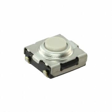
Button
A switch is an electrical component which can break an electrical circuit, interrupting the current
or diverting it from one conductor to another.
A Push Button is a type of switch which shorts or completes the circuit when it is pressed. It
is used in many circuits to trigger the systems. A spring is placed inside it to take it back in
initial or off position as soon as the button is released.
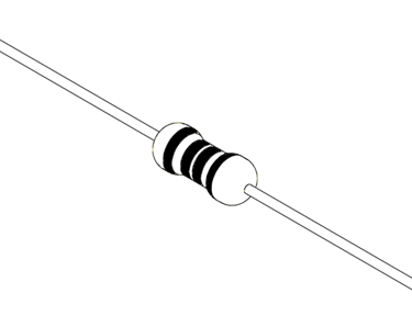
Resistor
Electrical resistance is a measurement of how difficult it is to carry an electric current through
the electric conductor. Free electrons move randomly within a conductor. The electrons clash with
other atoms and molecules of the conductor when an electric potential is applied to it.
Component used to create a resistance to flow a charge call as the resistor.
A Resistor is a passive two-terminal electrical component that implements electrical resistance
as a circuit element. In electronic circuits, resistors are used to:
• reduce current flow
• adjust signal levels
• divide voltages.
we can't connect the switch/button directly to the microcontroller because when the switch is not
pressed, input to a microcontroller is high Impedance state, which means input to a microcontroller
can be either logic '0' or logic 1'.
To avoid this, we use a resistor called a pull up resistor or pull-down resistor.
Pull up resistor:
The resistor is a pull-up resistor when we connect one terminal of a resistor to VCC and another
terminal of a resistor to a microcontroller input and switch.
When the switch is pressed, the microcontroller will receive logic 0 at the input because 0 volts
will appear across the input pin of the microcontroller as there is a flow of current through the
circuit.
Pull pull-down resistor:
The resistor is a pull-down resistor when we connect one terminal of a resistor to the ground
and another terminal of a resistor to a microcontroller input and switch.
When the switch is pressed, the microcontroller will receive logic 1 at the input because the entire
voltage will appear across the input pin of the microcontroller as there is a flow of current
through the circuit.
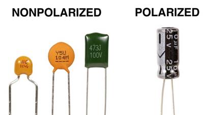
Capacitor
Capacitor is a passive component that has the ability to store the energy in the form of potential
difference between its plates. It resists a sudden change in voltage. The charge is stored in the
form of potential difference between two plates, which form to be positive and negative depending
upon the direction of charge storage.
A non-conducting region is present between these two plates which is called as dielectric. This
dielectric can be vacuum, air, mica, paper, ceramic, aluminum etc. The name of the capacitor is
given by the dielectric used.
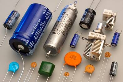
Capacitors with neither positive nor negative polarity are known as non-polarized capacitors.
Non-polarized capacitors’ two electrodes can be put into the circuit at random and will not leak.
They’re typically found in the coupling, decoupling, compensation, feedback, and oscillation
circuits.
Non-polarized capacitors are used in pure AC circuits and can also be used for high-frequency
filtering due to their modest capacitance.
Crystal
A crystal oscillator is an electronic oscillator that makes use of crystal as a frequency selective element to obtain an inverse piezoelectric effect. This frequency is often used to keep track of time, as in quartz wristwatches, to provide a stable clock signal for digital integrated circuits, and to stabilize frequencies for radio transmitters and receivers.
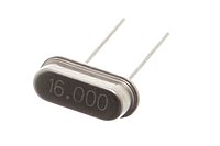
A ceramic resonator is an electronic component consisting of a piece of a piezoelectric ceramic material with two or more metal electrodes attached. When connected in an electronic oscillator circuit, resonant mechanical vibrations in the device generate an oscillating signal of a specific frequency.
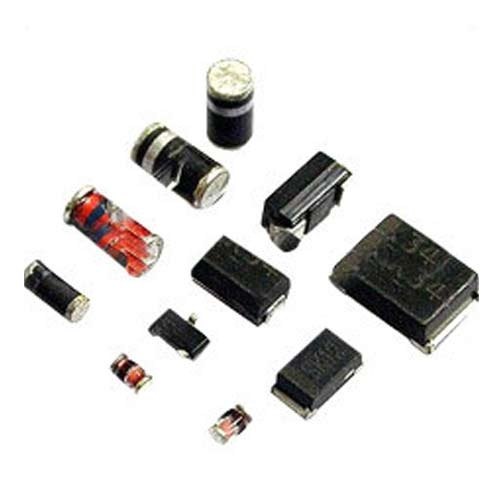
Diode
The most common function of a diode is to allow an electric current to pass in one direction while blocking it in the opposite direction As such, the diode can be viewed as an electronic version of a check valve. This unidirectional behavior is called rectification, and is used to convert alternating current (ac) to direct current (dc). it has low (ideally zero) resistance in one direction, and high (ideally infinite) resistance in the other.
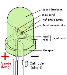
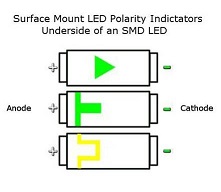
LED
These diodes convert the electrical energy in to light energy. First production started in 1968. It undergoes electroluminescence process in which holes and electrons are recombined to produce energy in the form of light in forward bias condition.
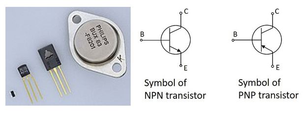
Transistor
A Transistor is a three terminal semiconductor device that regulates current or voltage flow and acts
as a switch or gate for signals. Transistors are used to amply the signals in the circuit.
Collector: its function of collecting the carriers.This is a bit larger in size than emitter and
base. It is moderately doped.
Emitter: This has a moderate size and is heavily doped as its main function is to supply a
number of majority carriers, i.e. either electrons or holes.
Base: Its main function is to pass the majority carriers from the emitter to the collector.
MOSFET
MOSFET is generally considered as a transistor and employed in both the analog and digital circuits. The main principle of the MOSFET device is to be able to control the voltage and current flow between the source and drain terminals.
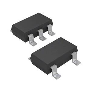
Microcontroller
A microcontroller (MCU for microcontroller unit) is a small computer on a single metal-oxide-semiconductor (MOS) integrated circuit (IC) chip. A microcontroller contains one or more CPUs (processor cores) along with memory and programmable input/output peripherals. Program memory in the form of ferroelectric RAM, NOR flash or OTP ROM is also often included on chip, as well as a small amount of RAM. Microcontrollers are designed for embedded applications, in contrast to the microprocessors used in personal computers or other general purpose applications consisting of various discrete chips.
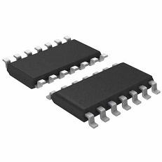
ATtiny44 Microcontroller
ATtiny (also known as TinyAVR) are a subfamily of the popular 8-bit AVR microcontrollers.AVR is a microcontroller family created by Atmel in 1996. These are 8-bit RISC single-chip microcontrollers with a modified Harvard design. AVR is one of the first microcontroller families to employ on-chip flash memory for program storage.
ATtiny44 Specifications
The ATTINY44-20PU is a low-power 8-bit CMOS Microcontroller based on the AVR enhanced RISC architecture. By executing powerful instructions in a single clock cycle, the ATtiny44 achieves throughputs approaching 1MIPS per MHz allowing the system designer to optimize power consumption versus processing speed. The AVR core combines a rich instruction set with 32 general purpose working registers. All 32 registers are directly connected to the arithmetic logic unit (ALU), allowing two independent registers to be accessed in one single instruction executed in one clock cycle. The resulting architecture is more code efficient while achieving throughputs up to ten times faster than conventional CISC microcontrollers. The ATtiny44 provides 4kB of in-system programmable flash, 256byte EEPROM and 256byte SRAM. The device supports a throughput of 20MIPS at 20MHz.
Some Basic Components: the unit, pin name and no of terminals:
| Some Basic Components: the unit, pin name and no of terminals: | ||||
|---|---|---|---|---|
| Component | Denoted by | Unit | Polarity/Pins | Terminals |
| Resistor | R | Ohms(Ώ) | Not | 2 |
| Capacitor | C | Farads(f) | Anode-Cathode | 2 |
| Diode | D | Anode-Cathode | 2 | |
| Inductor | L | Henry(H) | Not | 2 |
| Transistors(BJT) | NPN/PNP | - | Emitter, Base, Collector | 3 |
| Transistor(MOSFET | n-Channel, P-Channel | - | Drain, Source, Gate | 3 |
| Relay | - | - | NC, NO, C, 2-Coil Pins | 5 |
| Power Sources | - | Voltage, Current | Positive, Negative | 2 |
| Motor | M | RPM | Positive, Negative | 2 |
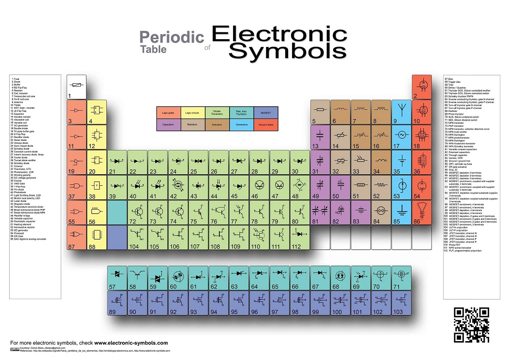
Periodic Table of Electronic Symbols
• Individual assignment:
• Redraw one of the echo hello-world boards or something equivalent, add (at least) a button and LED (with current-limiting resistor) or equivalent input and output, check the design rules, make it, test it. Optionally, simulate its operation.
Electronic Design
This week, the individual assignment is to make Hello echo board of Neil with one led and switch button. And group assignment is to use the test equipment in your lab to observe the operation of a microcontroller circuit board. There are several online and offline software available for designing a PCB. Mostly, they have the same workflow.
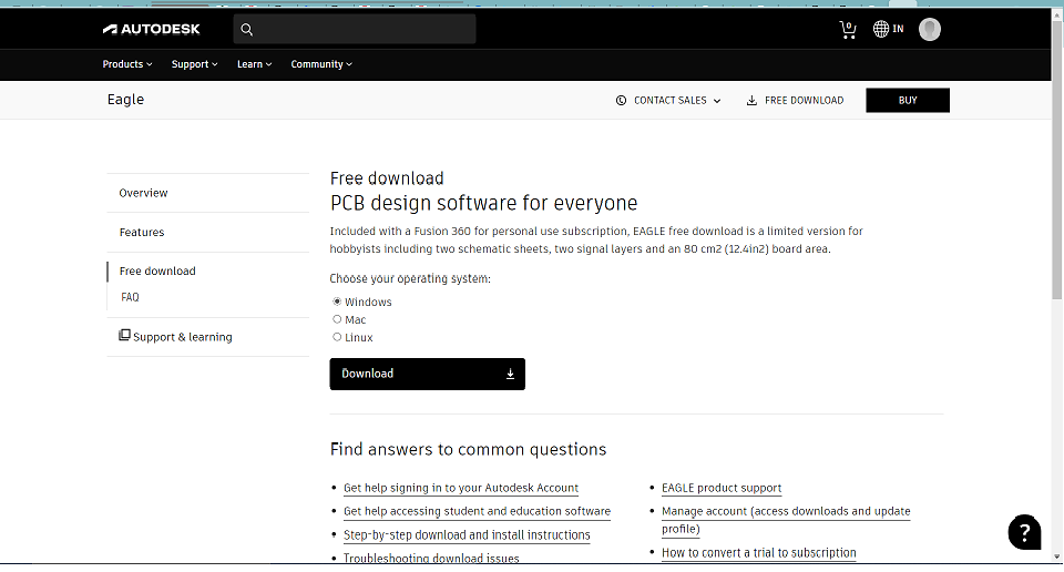
I have chosen to move with Eagle Software for PCB design for this assignment.
I have downloaded the software from the Autodesk website and installed it by conventional procedure.
Eagle Software Download
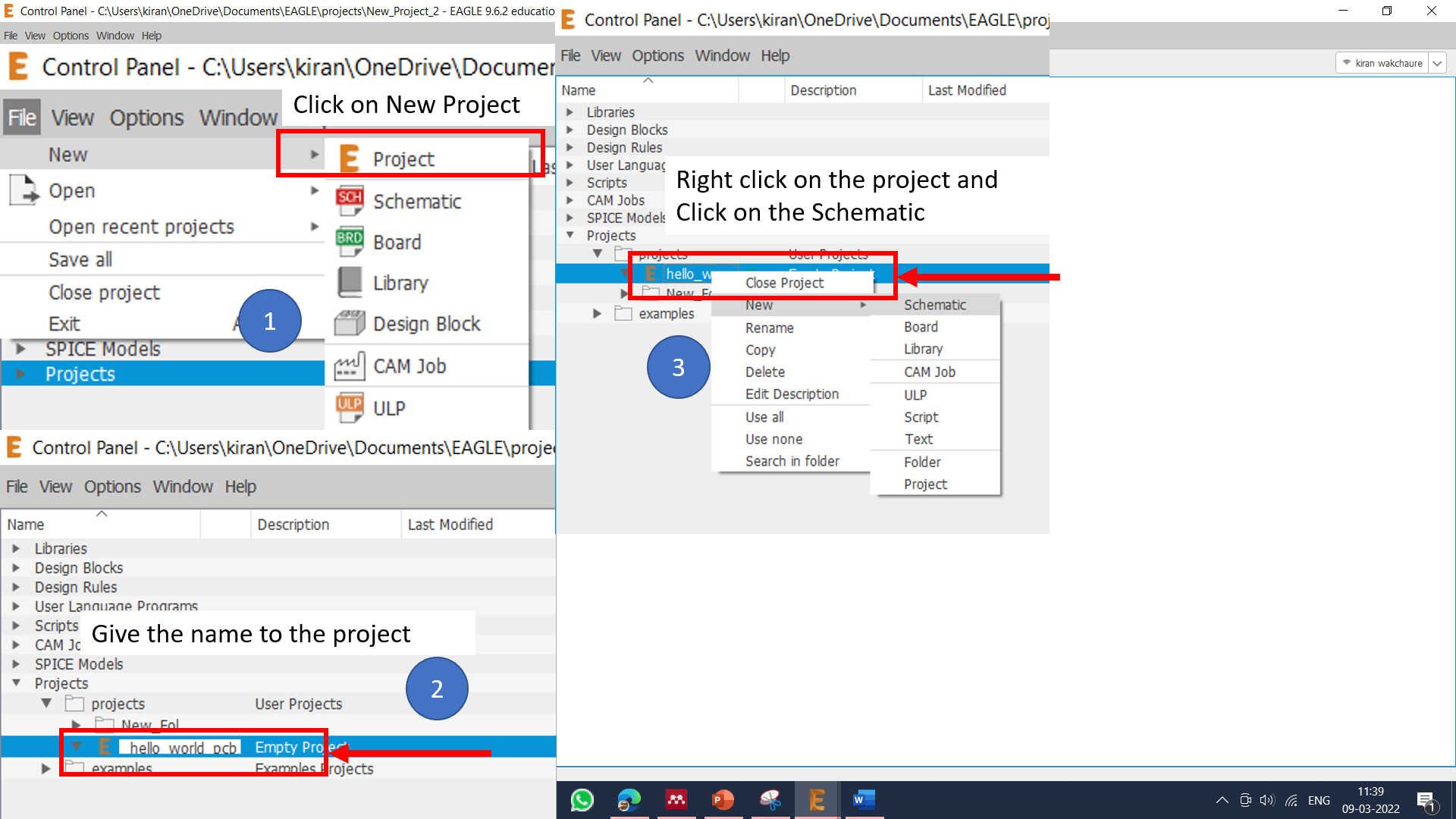
I have started a new project in Eagle software.
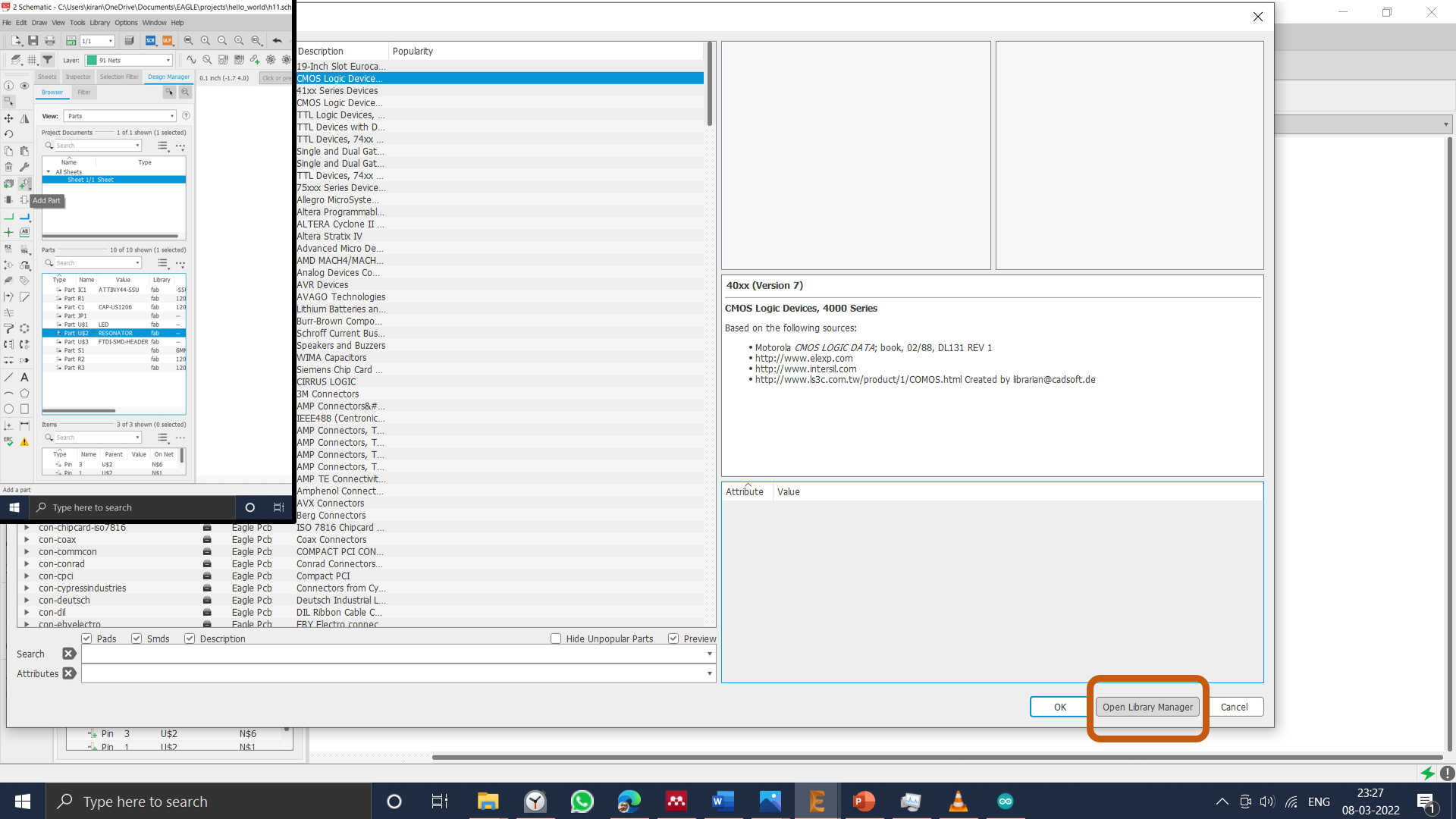
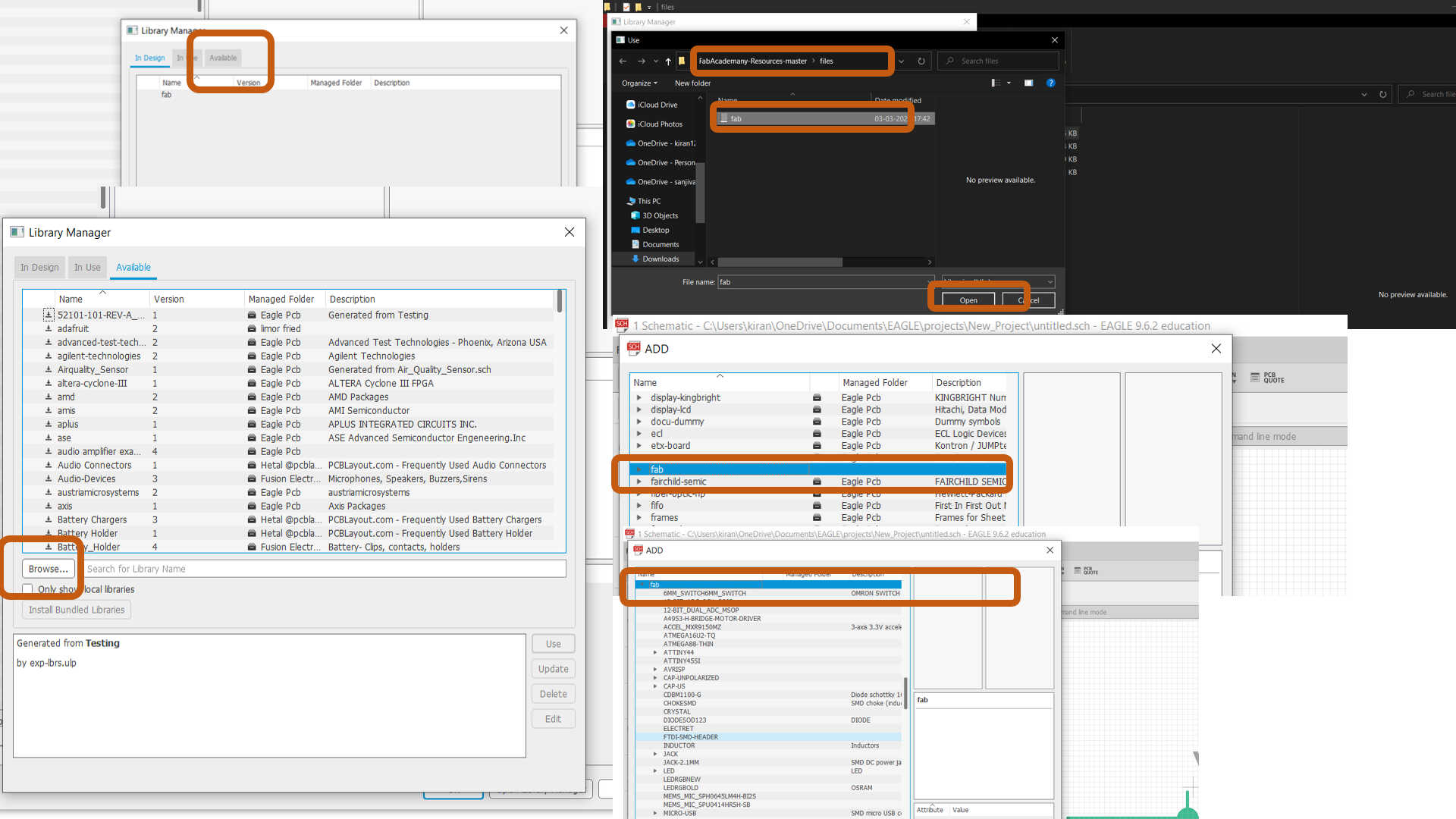
Next step is to add the fab library to eagle library manager because I got the footprints of the component from that library, which I will use to design the Hello echo board.

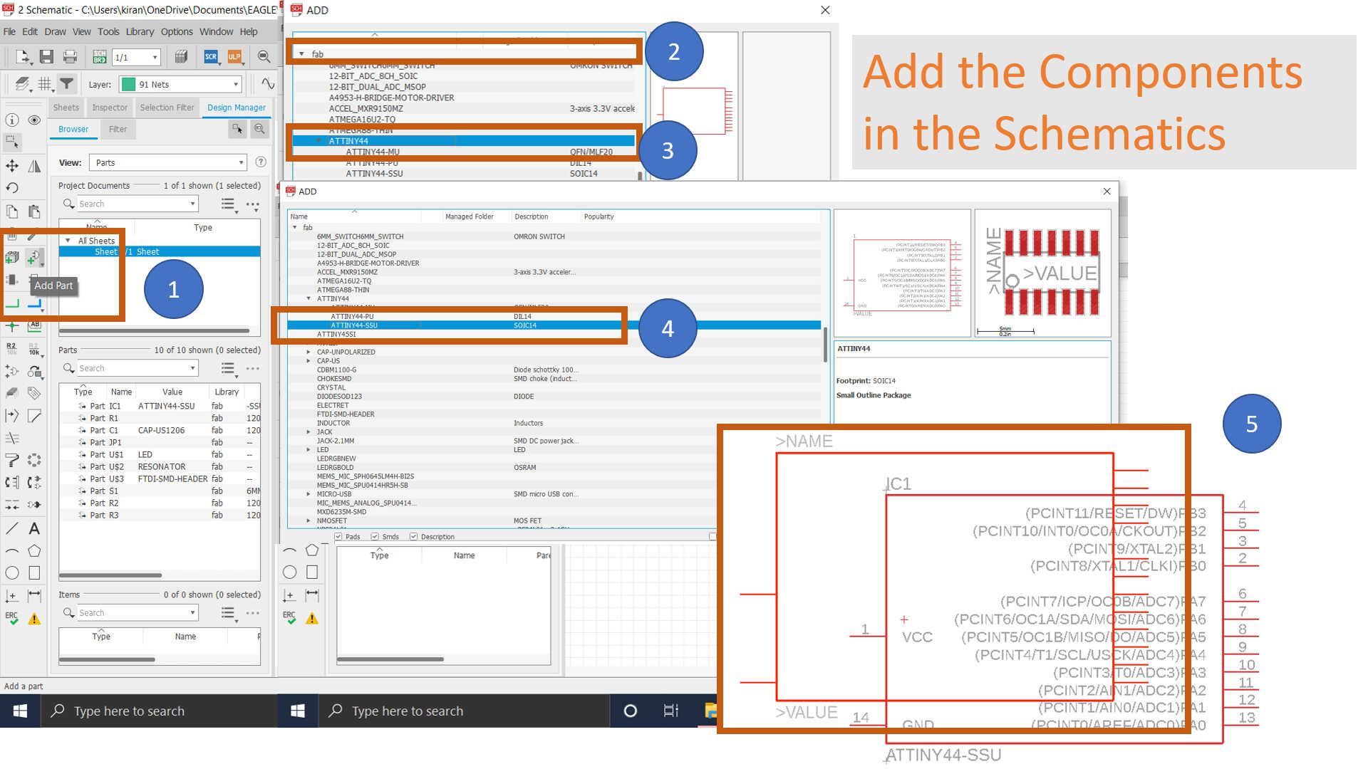
After adding the Fab components library I have starts the schematic of Hello word PCB.
Right-click on the new project and click on the schematic. Schematic is simply a line diagram or connections of all the components on your board. In the schematic, you can add, select, group, re-arrange, etc. the components. The menu on the left side has all these options and is self-explanatory.
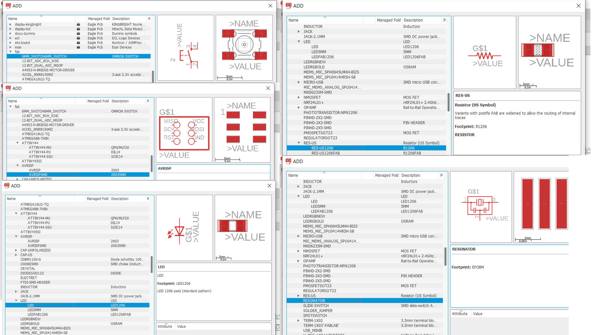
And after adding the component required to design the board. I followed these steps.
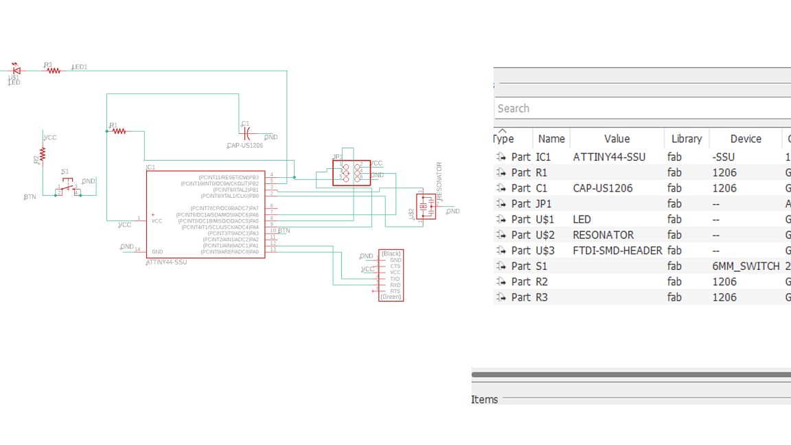
1. After adding all the components, select the line tool and draw a small line on the terminals
of each element.
2. Add Label to the terminal lines and then Name them.
3. The terminals with the same name are automatically connected, you'll be prompted before that.
Connecting components rather than drawing lines from one terminal to another is easy, less messy,
and more understandable.
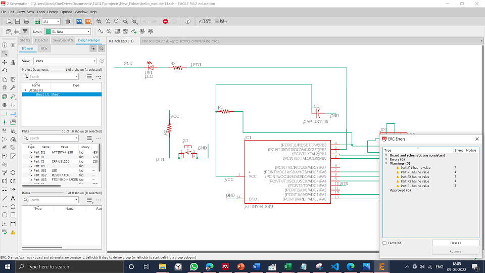
I started with Electronics rule checking after adding the appropriate components and creating
connections (ERC). If the board file has been loaded before initiating the ERC, the ERC command will
also run a Consistency Check between a schematic and its matching board. Then, on the command line,
type ERC to check for errors in the schematic. When I first verified my schematic, these were the
errors I encountered. ERC is a useful tool that highlights frequent mistakes in your schematic. An
ERC will check the following issues:
Are all of your nets on your schematic correctly linked and labeled?
Do you have any incompatible outputs/inputs on your schematic?
Are there any pins and ports on your schematic that are open or overlapping?
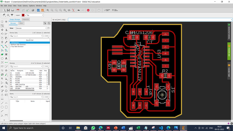
Now come to board: The window opened when the SCH-BRD button on top clicked
1. The board represents the physical board; all components in the Board window are organized by
their footprint size.
When you open the barred window, you can see all the components on the bottom left. Your canvas
for your remarks is the black space with a red outline.
3. An air wire, which is a yellow line, connects the component to the rest of the system. These
are used to show how the various components are linked together.
4. Layers: There are a number of layers on which you can route or add components. I used the
top layer for routing and the bottom layer for the border outline for my board.
5. Arrange all components on the canvas; remember to hit the Ratnest every time you place or
move a component. The airlines will be better rerouted as a result.
6. Instead of using Autorouting, I choose to handle everything manually.
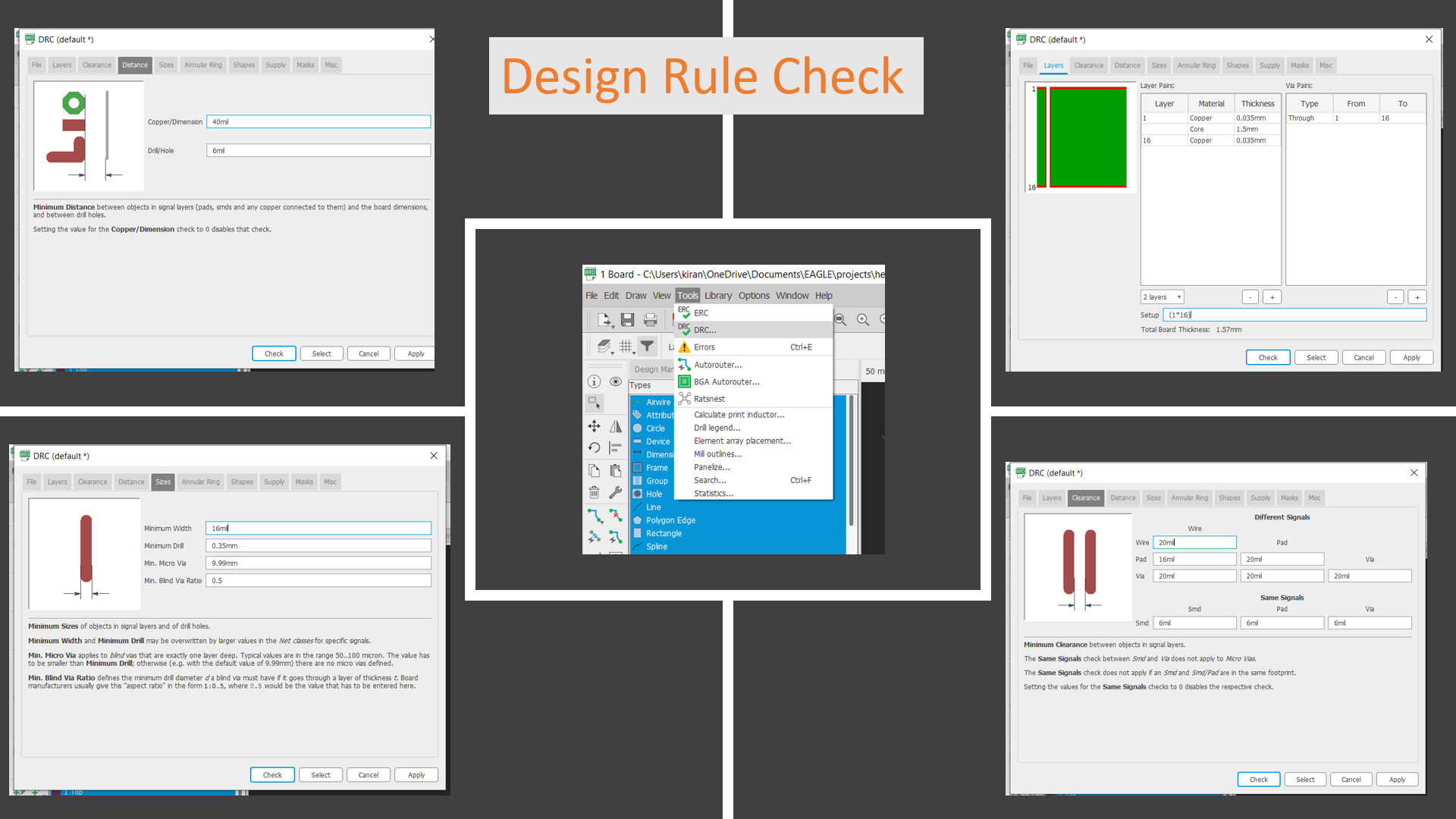
Design rules set for the board areas follows
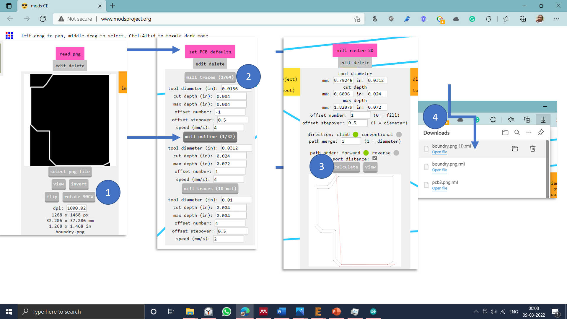
After drawing the board, next, I have converted traces separately into png file for machining on milling machine
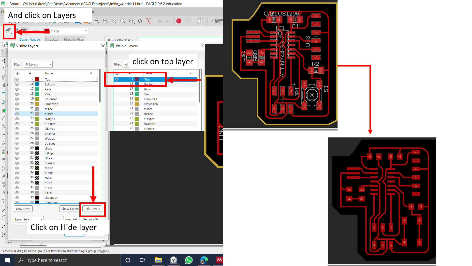
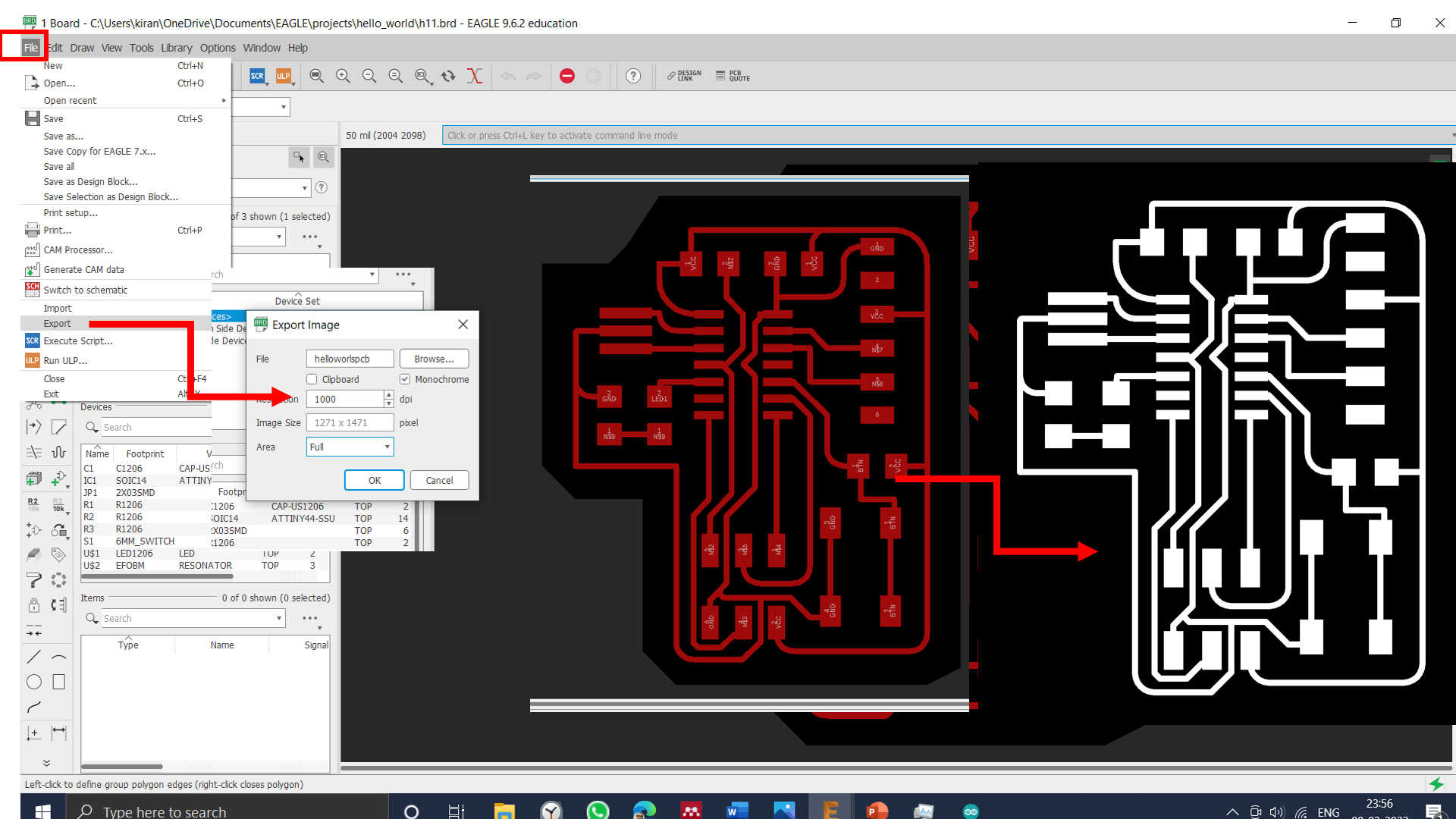
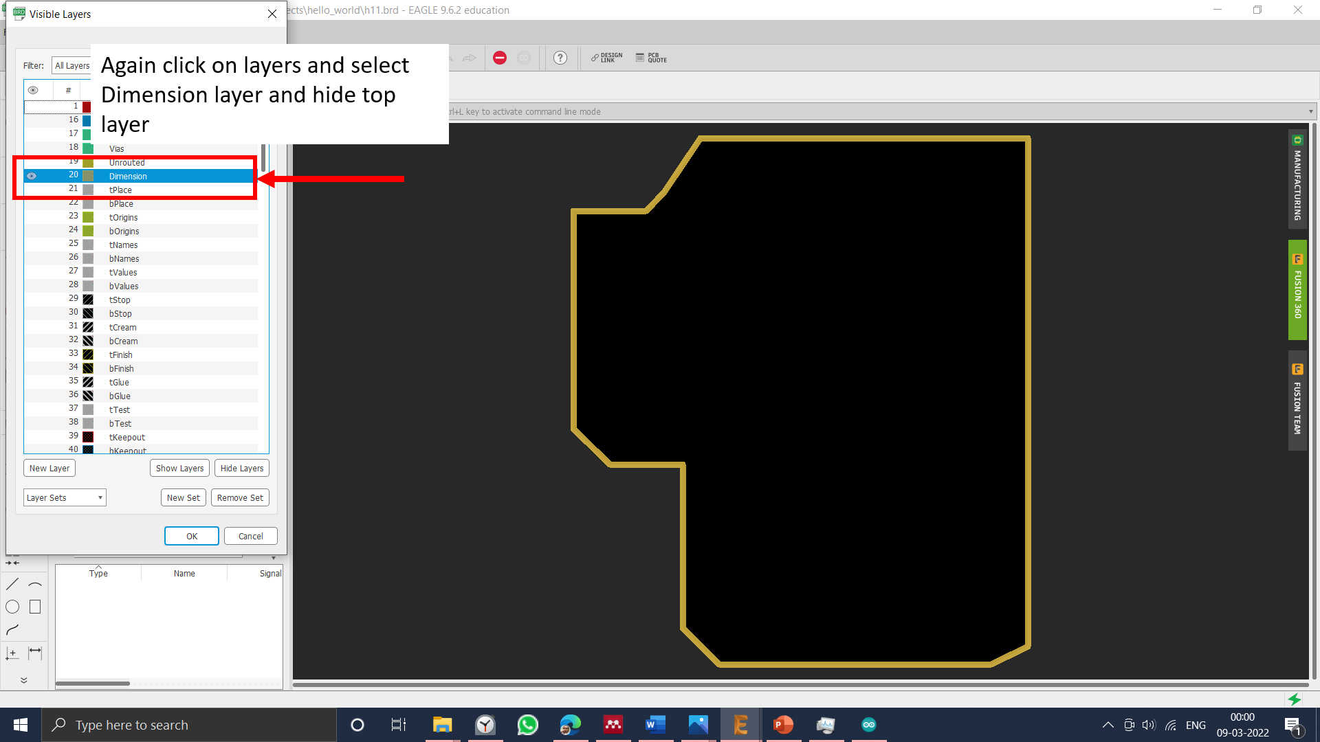
Then I have converted exterior into png file.
Machining and soldering of the PCB Board
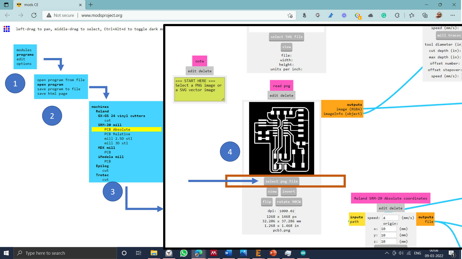
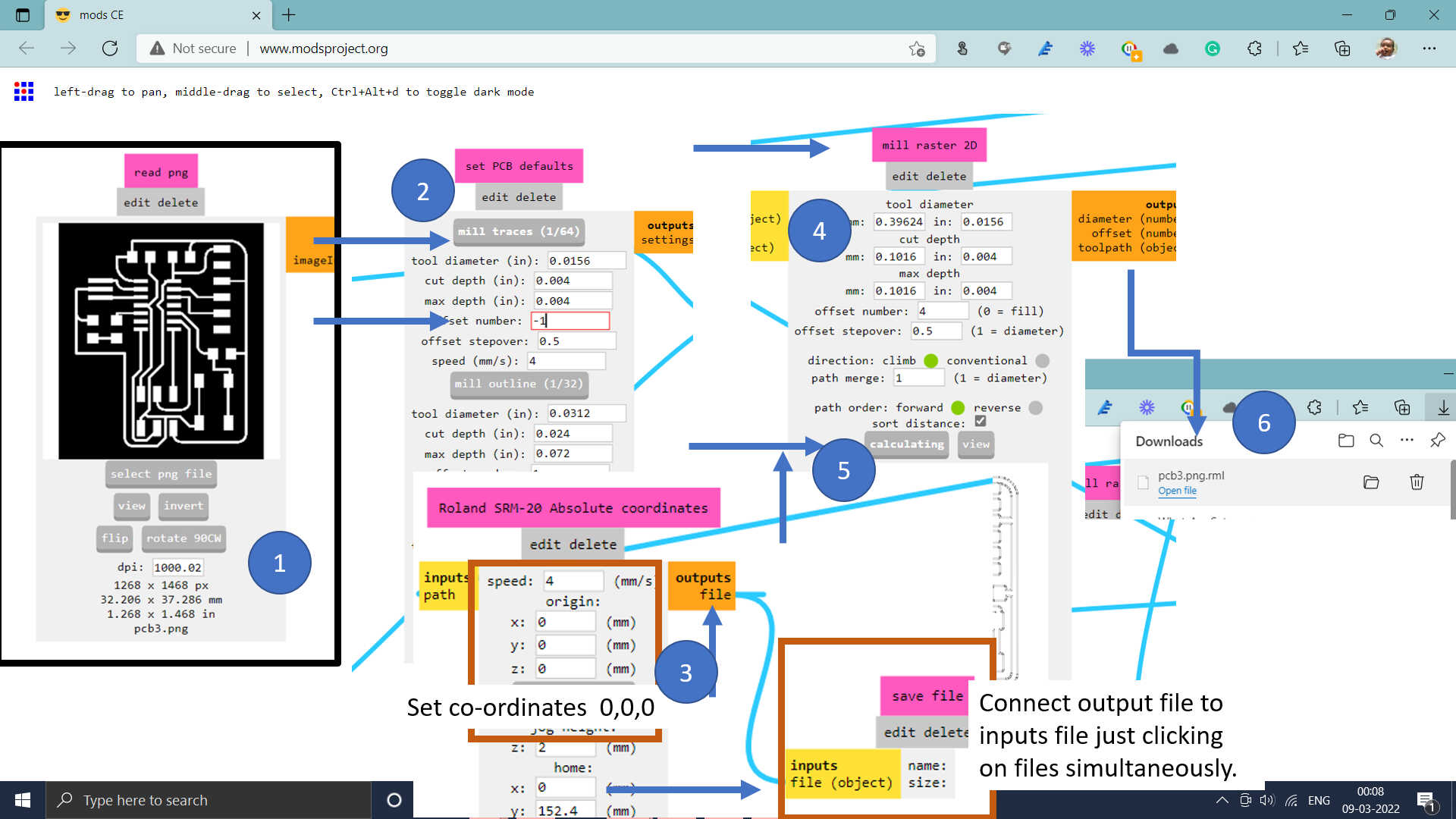
The tool path for .rml file is the same as the process done in Electronics Production week.
Soldering Operation :SMD components are used for soldering.
• Resonator SMD 20 Mhz
• IC Attiny44
• ISCP -2x3 Male header Pins
• Resistor 10K and 0.1K
• Capacitor 1mF
• 1206 (1- LED)
• Push Button SMD
• 1x6 Male header Pin
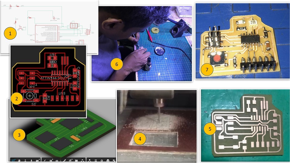
Testing and Programming of the PCB Board
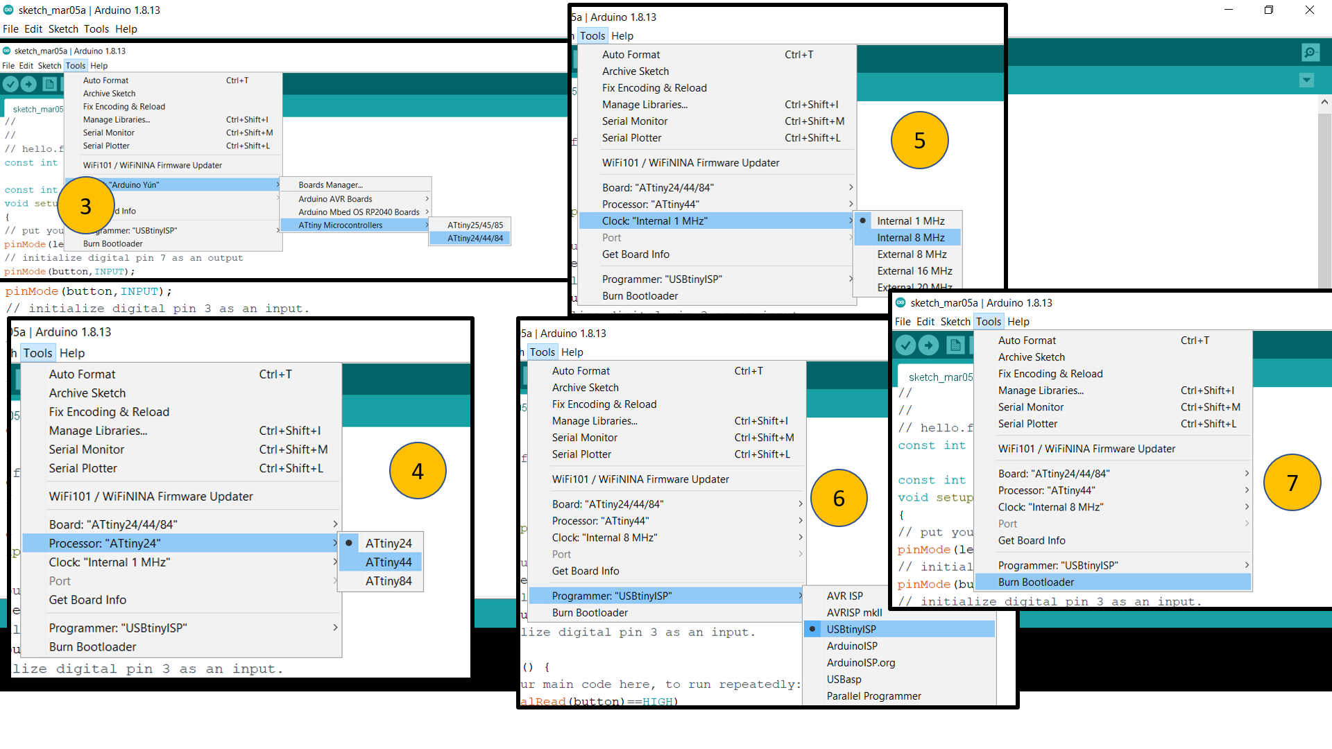
I have connected my board with Fab ISP. I have used Arduino IDE to program my board. To program ATtiny44v board I need to add some libraries, as shown below.
Link to download Attiny Libraries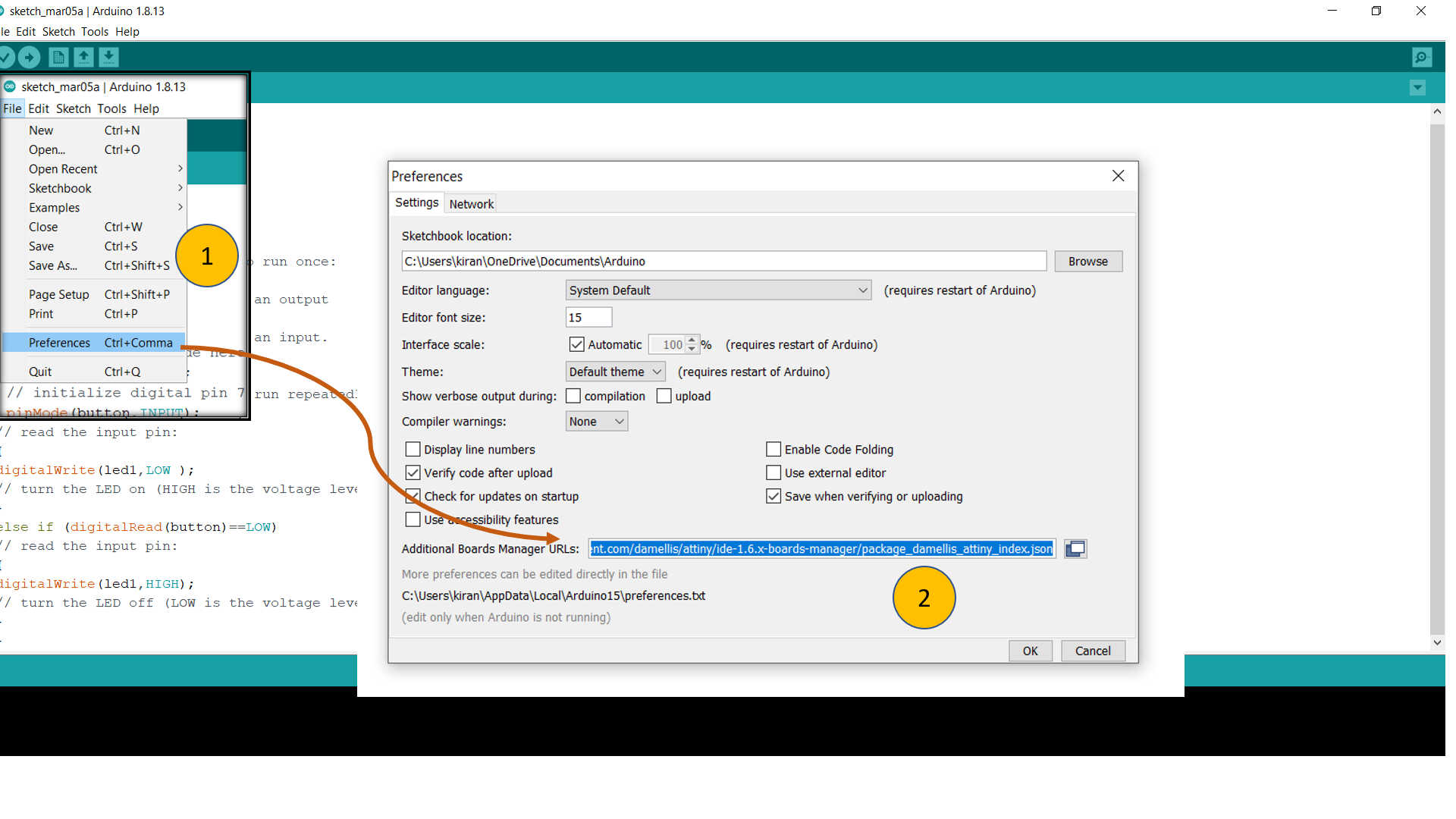
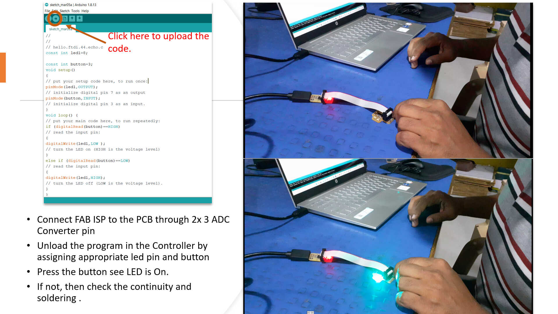
Final Testing
Group Assignment
You can find a detailed Group assignment here.
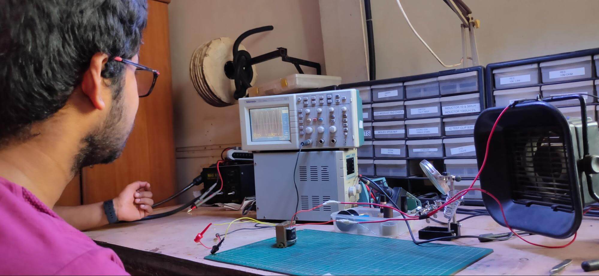
This assignment is about documenting what we learned in Electronics Design week, including working on test equipment in our lab to observe the operation of one of the echo Hello world boards that we designed this week in our assignment. We checked the operating voltage on the board with a multimeter. We used an oscilloscope in our lab to check different waveforms the board was generating at various points in the circuit. We also observed the noise in operating voltage and interpreted a blinking LED signal on the board. We used the variable power supplier in the lab to find out how much current the board is consuming and what is the operating voltage for LEDs
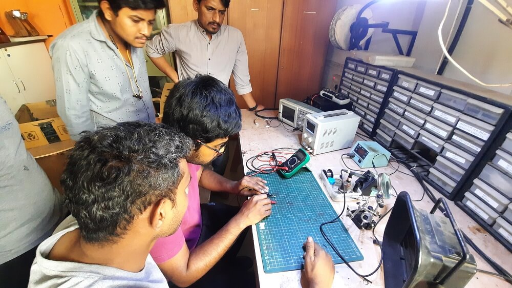
Equipment need to be Tested:
- Multimeter
- Variable Power Supply
- Digital Storage Oscilloscope
Multimeter
This series instrument is a tiny hand-held 3 1/2 digital multimeter with good stability, reliability, and anti-drop performance. It has a 15 mm high LCD display that allows for easy reading. The circuit design incorporates an LSI double integral A/D converter as its core, which is protected by an overload protection circuit, resulting in a superior and practical instrument. It can be used to test in-circuit continuity and measure DC and AC voltage, DC current, resistance, diodes, transistors, and temperature.

Voltage test: Real time voltage consumption at eco Hello World board
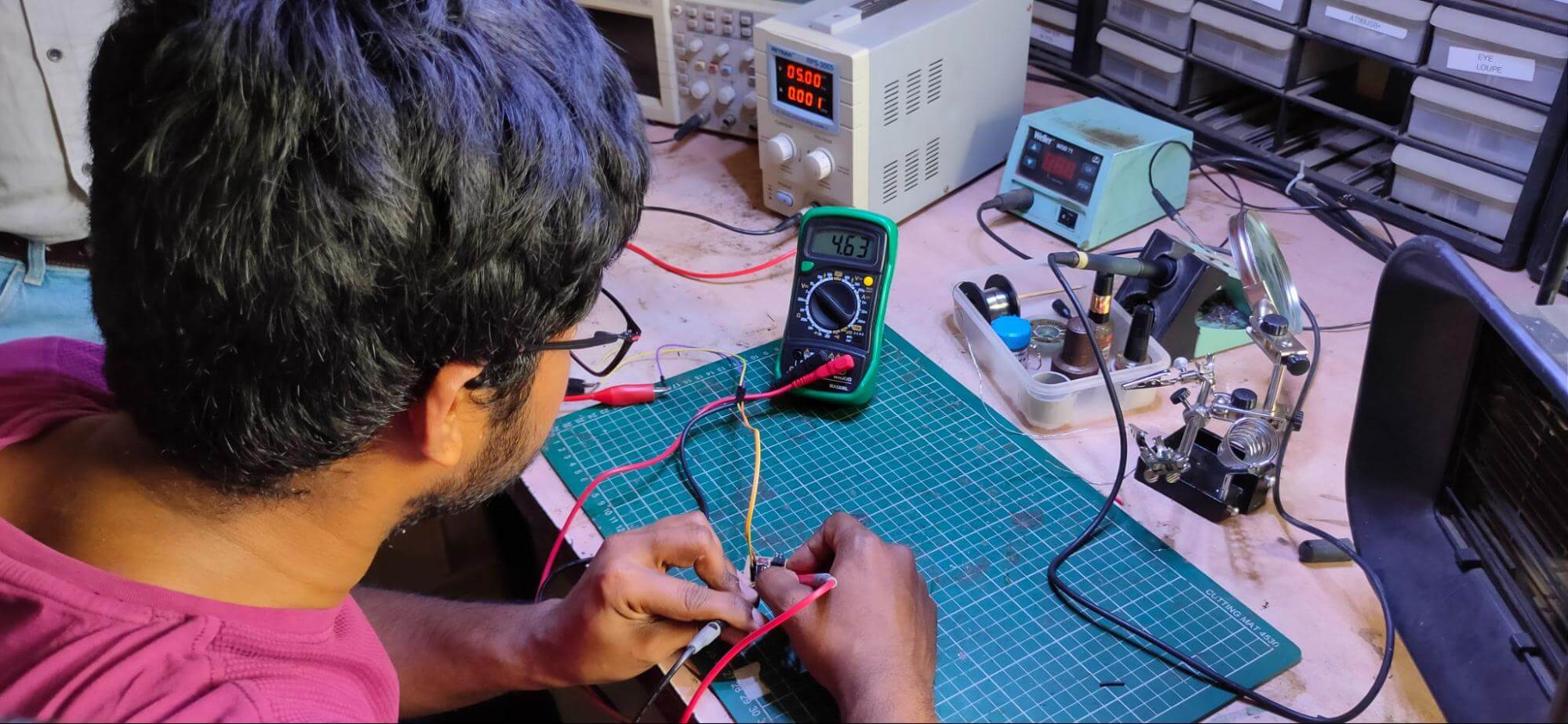
Testing LED current using multimeter
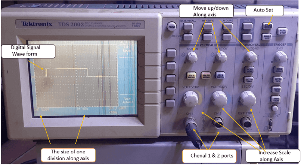
Digital Signal Oscilloscope
The digital storage oscilloscope is a device that allows you to save a digital waveform or a digital duplicate of one. It allows us to store the signal or waveform in digital format, as well as perform digital signal processing techniques on that signal, in digital memory. The maximum frequency measured on a digital signal oscilloscope is determined by two factors: the scope's sampling rate and the converter's type. DSO's traces are bright, well-defined, and appear in a matter of seconds.
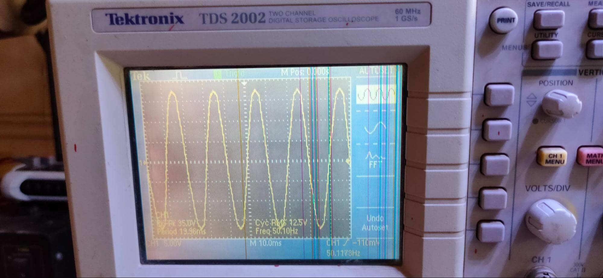
AC current Wave form output:
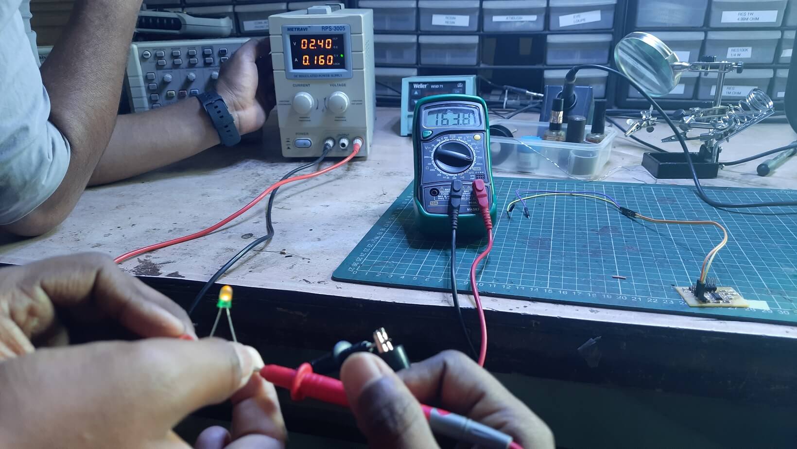
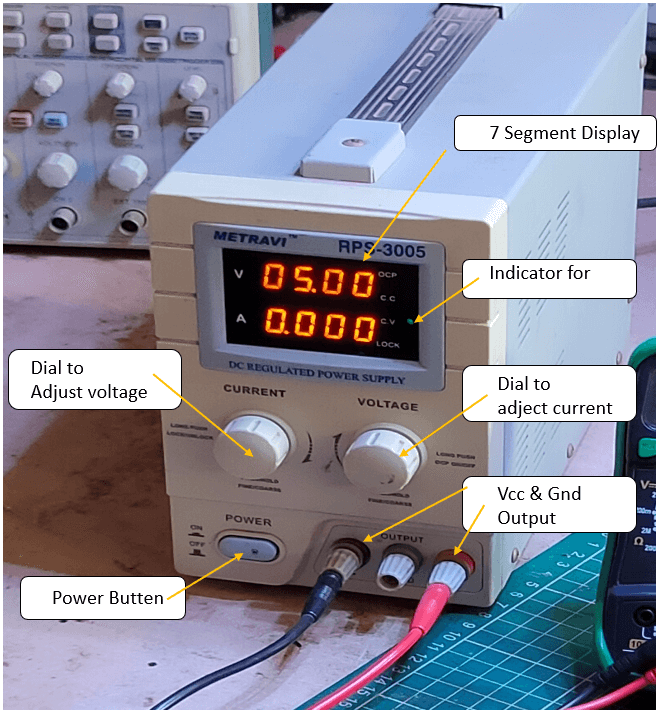
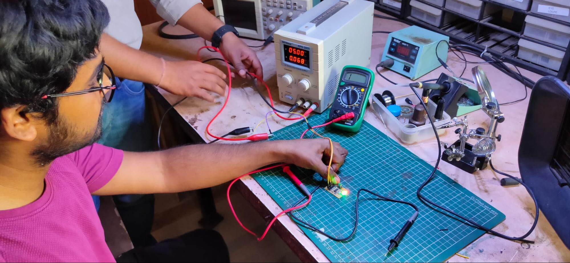
Testing RPS-3005 DC Regulated Power Supply
At Vigyan Ashram Fab lab, we have a DC Regulated Power Supply of Metravi RPS-3005 with Single Output and Backlit LCD Display of variable 0 - 30V / 0 - 5A DC utilizing SMT technology. A reliable, heavy-duty DC power supply suitable for lab work, research, R&D, and industrial use. Its linear design makes for quiet, stable operation with virtually no ripple and minimal delay during conversion, transformation, and adjustment. With a maximum output of up to 30 volts and a current capable of 5 amps, the Metravi RPS-3005 has several other beneficial features: two fully operational modes, back-lit LED display with a clear resolution, above-average LCD accuracy (+/- 2.%), and programmable voltage and current. Constant voltage mode and constant current mode are the two operational modes, where you can limit your supply up to a certain limit to avoid the excess flow of power. A DC power supply is an electrical device that converts the AC to DC current Supply using a rectifier circuit.
The board consumes around 5V and 0.068 A to power up. Therefore, the power consumed by the board with LED on = 5V x 0.068A = 0.34 W. In this way, we calculate the power consumption of any circuit or device.
Downloads
Board and Schematic Files, PNG files of traces and exterior and Program file.
Board and Schematic Files, PNG files of traces and exterior and Program file. .