Computer-Aided Design
“If you tell me, I will listen. If you show me, I will see. If you let me experience,
I will learn!”
— Lao Tzu (6th Century BC)
2D Design-Raster and Vector
Raster
Raster images use bit maps to store information. This means a large file needs a large bitmap. The larger the image, the more disk space the image file will take up.. Scaling these photos down is simple, but increasing them causes them to become pixelated or just indistinct. As a result, we employ vector graphics to create pictures that can be scaled to multiple sizes. File extensions: .BMP, .TIF, .GIF, .JPG
Vector
Vector Graphics is a term that refers to the use of sequential instructions, mathematical expressions, or algorithms to arrange lines or forms in a two-dimensional or three-dimensional environment. Because vector graphics are constructed of a sequence of mathematical curves, they are ideal for printing. As a consequence, vector designs print crisply at any size. File extensions : .SVG, .EPS, .PDF, .AI, .DXF
1. Gimp
For Image editing I started learning with Gimp. GIMP is a free and open-source raster graphics editor used for image manipulation and image editing, free-form drawing, transcoding between different image file formats, and more specialized tasks. I have done image editing, image compression, and some simple tasks with GIMP. Since long I want to create my own logo. In this assignment, I have created my logo using the GIMP tool.
Getting Started with GIMP to create logo
I have used the GIMPto create my logo. I have followed youtube Video to add the shadow effect.
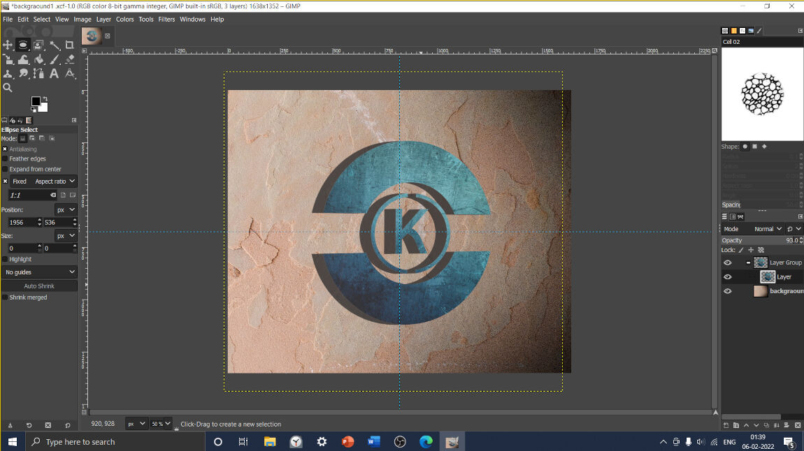

Final Logo

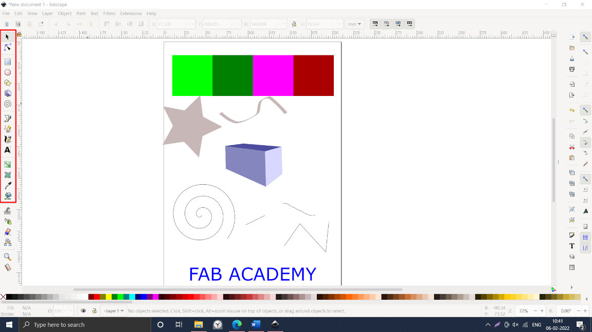
2. Inkscape
For the vector graphics, I started with Inkscape. Inkscape is a free and open-source vector graphics editor used to create vector images. I started with Inkscape tutorials
Some basic features
I have used some basic features to get familiar with GUI of Inkscape.
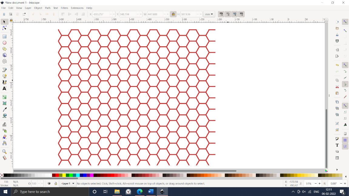
I ve followed YouTube Inkscape Tutorial to create Honeycomb mesh.
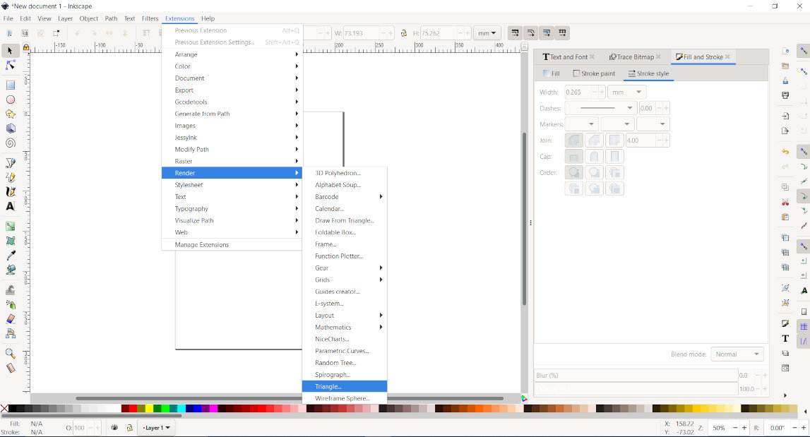
I have created honeycomb mesh with triangle by using clone feature which can be further useful for parametric modelling.The procedure is as follows:
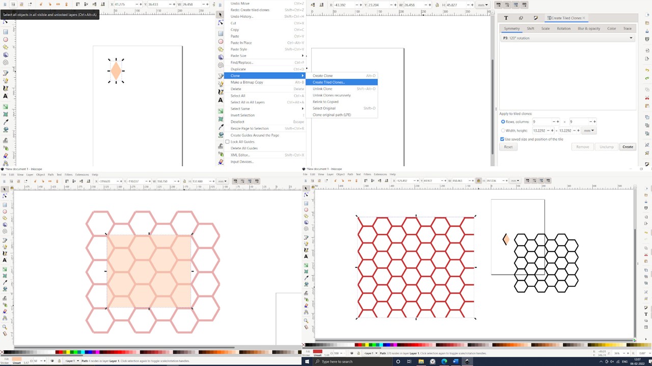
Final Honeycomb mesh
3D Modelling
3D modelling provides another depth to 2D modelling. 3D modelling is utilized to provide an accurate visual representation of the design. 3D modelling is used to provide an accurate image of the model from all angles. Three-dimensional models are further used in Additive manufacturing, computer aided manufacturing, Finite element analysis, animation, and gaming industry.
1. Solidworks
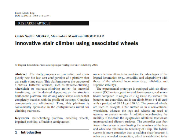
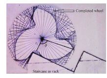
Solidworks is a powerful tool that provides a complete solution for product design and development. Solidworks consists of CAD, CAM, FEA, PCB, ROUTING, Harnessing, and AR/VR capabilities. I had explored Solidworks earlier for some projects. I thought I needed to explore Solidworks in more detail. One of my professors, Dr. G. S. Modak has developed a stair climbing wheel. I was very fascinated by this. So, I decided to do some modelling and simulation of the Stair Climbing Wheel. I have referred to his research paper to understand the basic requirements of it. To develop the profile of the wheel, I needed to generate a logarithmic spiral using the equation. Doing the motion simulation was the most challenging task for me. Dr. Modak has design the wheel for step height of 150mm and width of 300mm. I have considered 1:10 scale.
Research Paper
"
Model developed
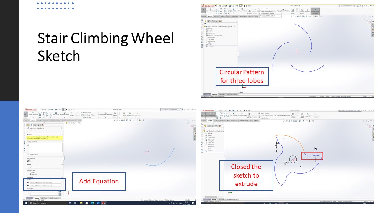
GUI of Solidworks.
This is GUI of Solidworks. To draw the sketch we need to select the plane on which we need to draw.
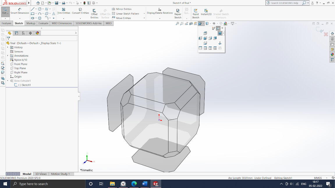
Sketch feature.
Here I have selected front plane and select in tool-Sketch tools- Equation editor.
Nature of the curve: logarithmic spiral x(t)=10.2356*(exp(0.837758*t))*cos(1.675516*t) y(t)=10.2356*(exp(0.837758*t))*sin(1.675516*t)
Circular Pattern
Circular array is used to create 3 lobes .
To close the sketch required trajectory is drawn. Then exit the sketch mode and extruded the geometry.
Final Stair wheel sketch.
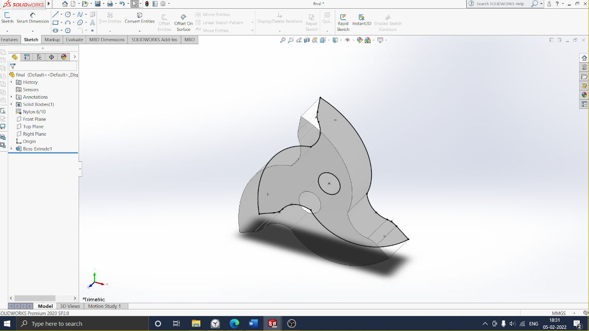
Extrude feature
Sketch is extruded for required thickness.
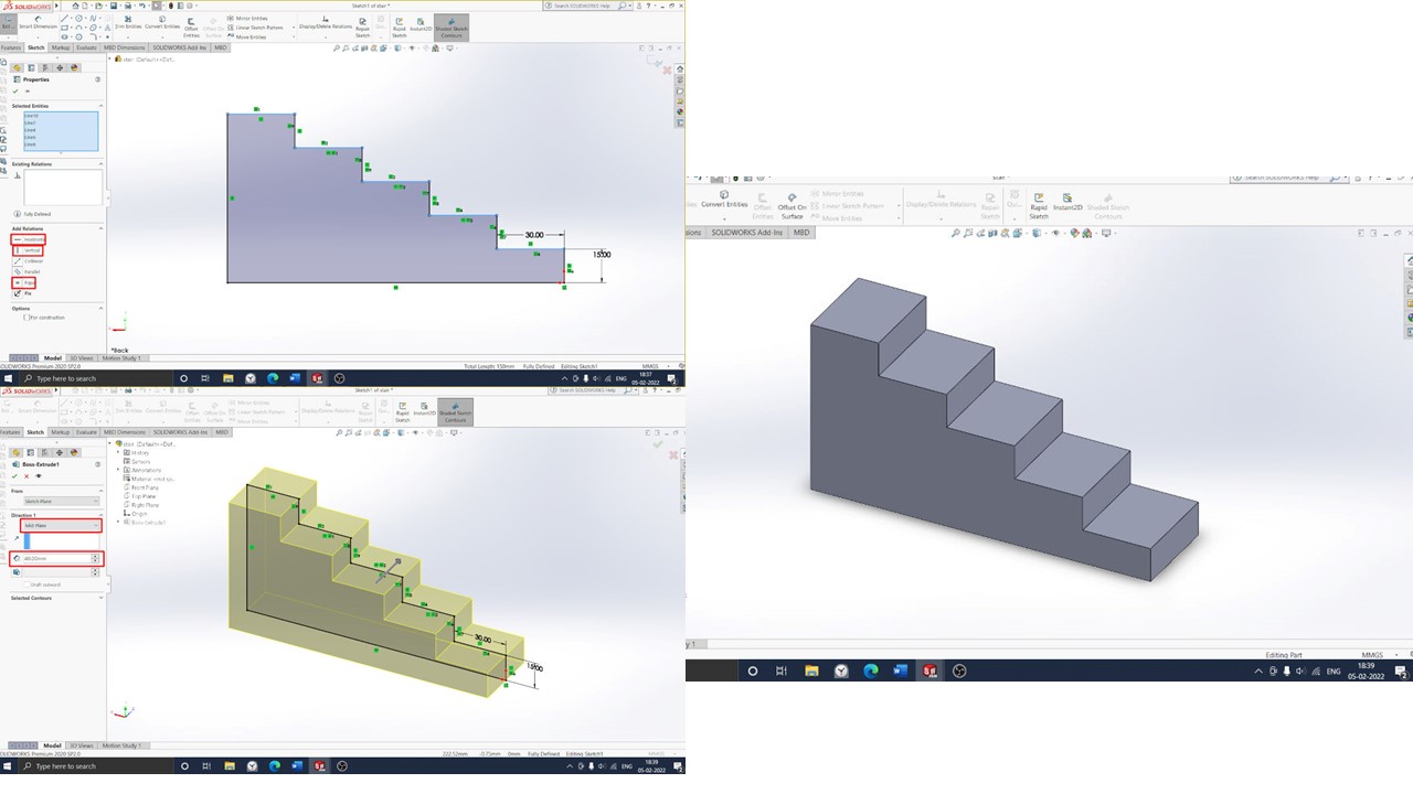
Stairs Sketch
Then Stairs were modelled with 150 mm width and 100 mm height.
Assembly of wheel and Stairs was done using Assembly feature.
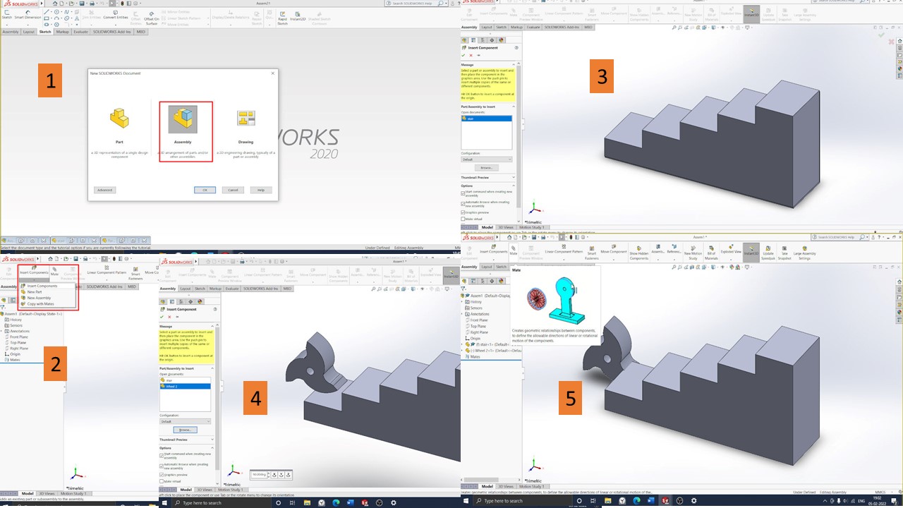
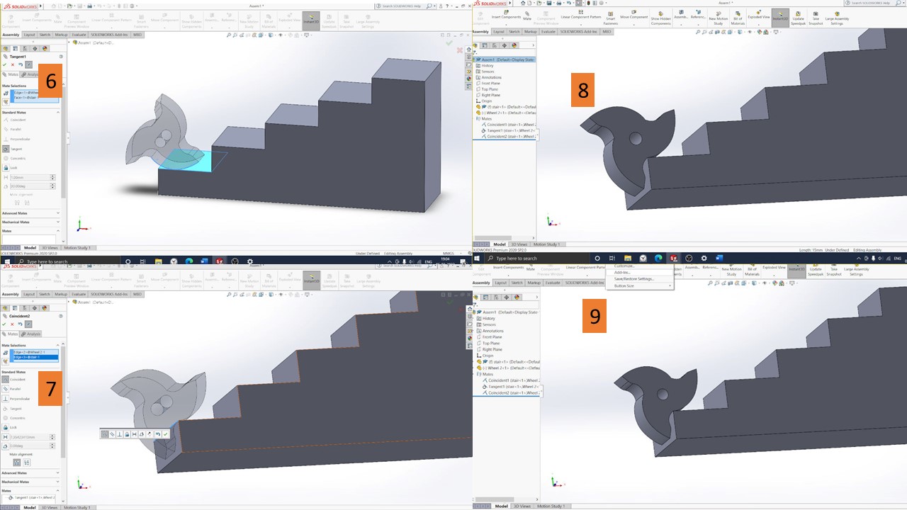
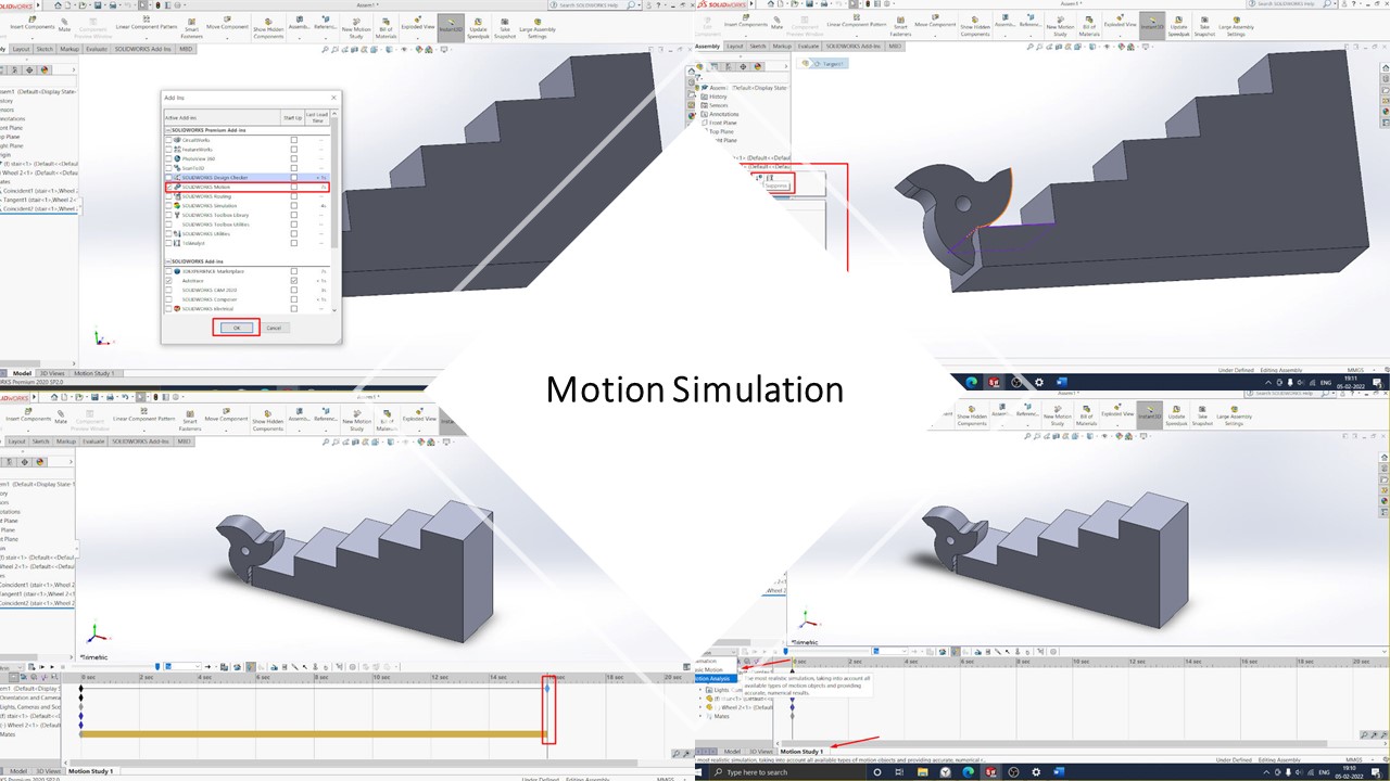
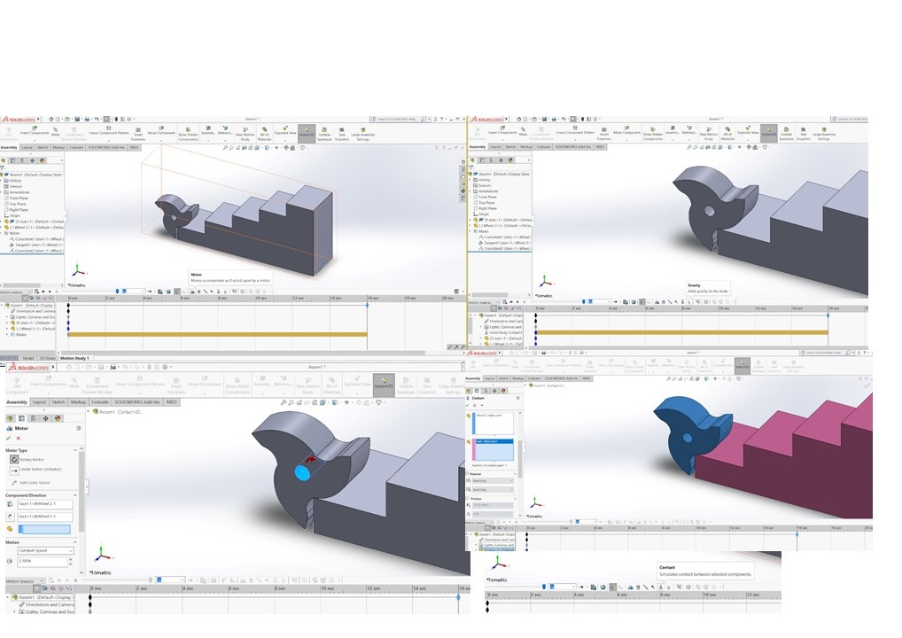
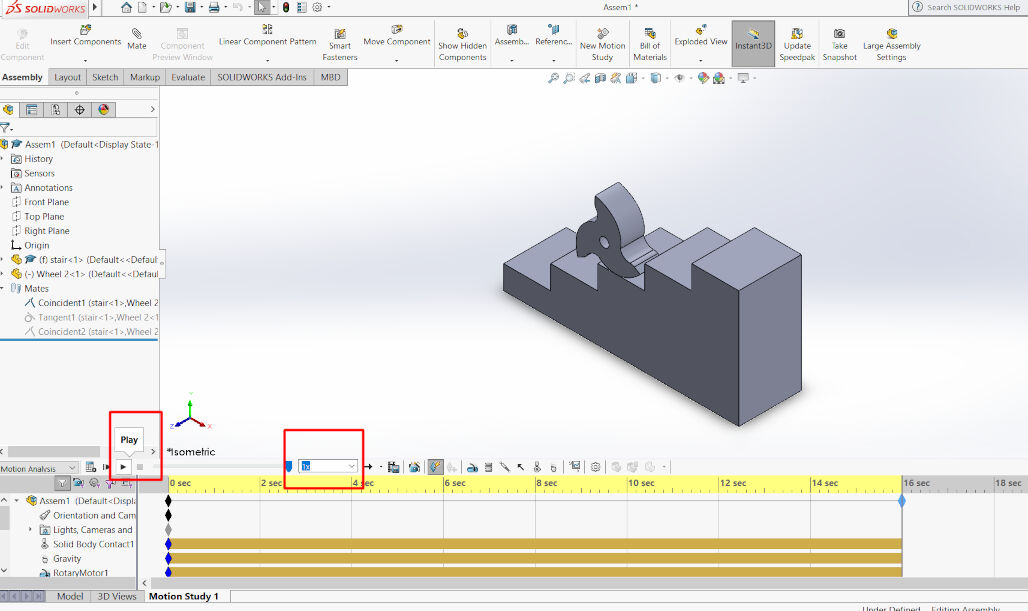
Motion Simulation
After completing the assembly, motion simulation Add in added to do the simulation stair climbing.
Step 32
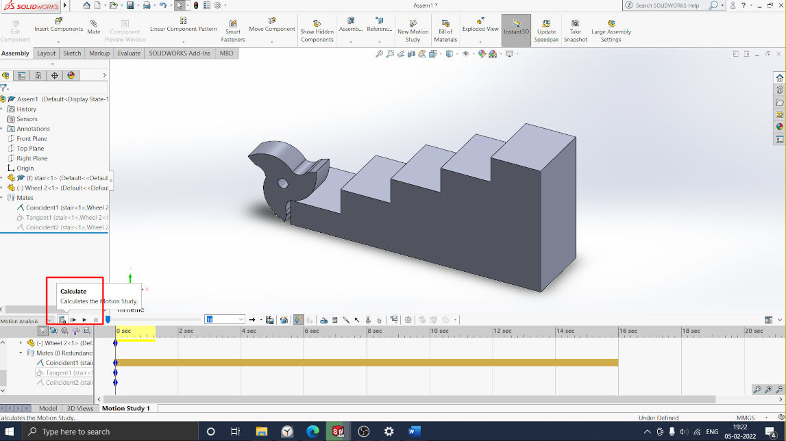
Calculate and play the Simulation
Simulation
And a short video to showcase it use:
2. Fusion software
Description
Fusion 360 is also a powerful 3D CAD package from Autodesk Inc. and is gaining popularity due to its cloud based operating system. I had not used Fusion 360 earlier.
Due to the simple GUI, it was a nice experience to use Fusion. Initially, I tried the basic extrude, revolve, and sweep commands, and then I thought I would do a simulation of the 4Bar mechanism using Fusion 360. I tried to study Grashof’s Law for the 4-Bar Mechanism.
Grashof’s Law states that for a four-bar linkage system, if the sum of the shortest and longest links of a planar quadrilateral linkage is less than or equal to the sum of the remaining two links, then the shortest link can rotate fully with respect to a neighboring link. I started to create four linkages of different lengths. Assemble them with the revolute pair and animate them for kinematic analysis.
The whole procedure is described here.
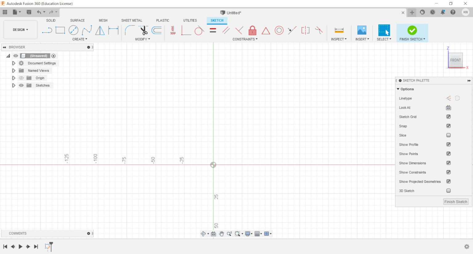
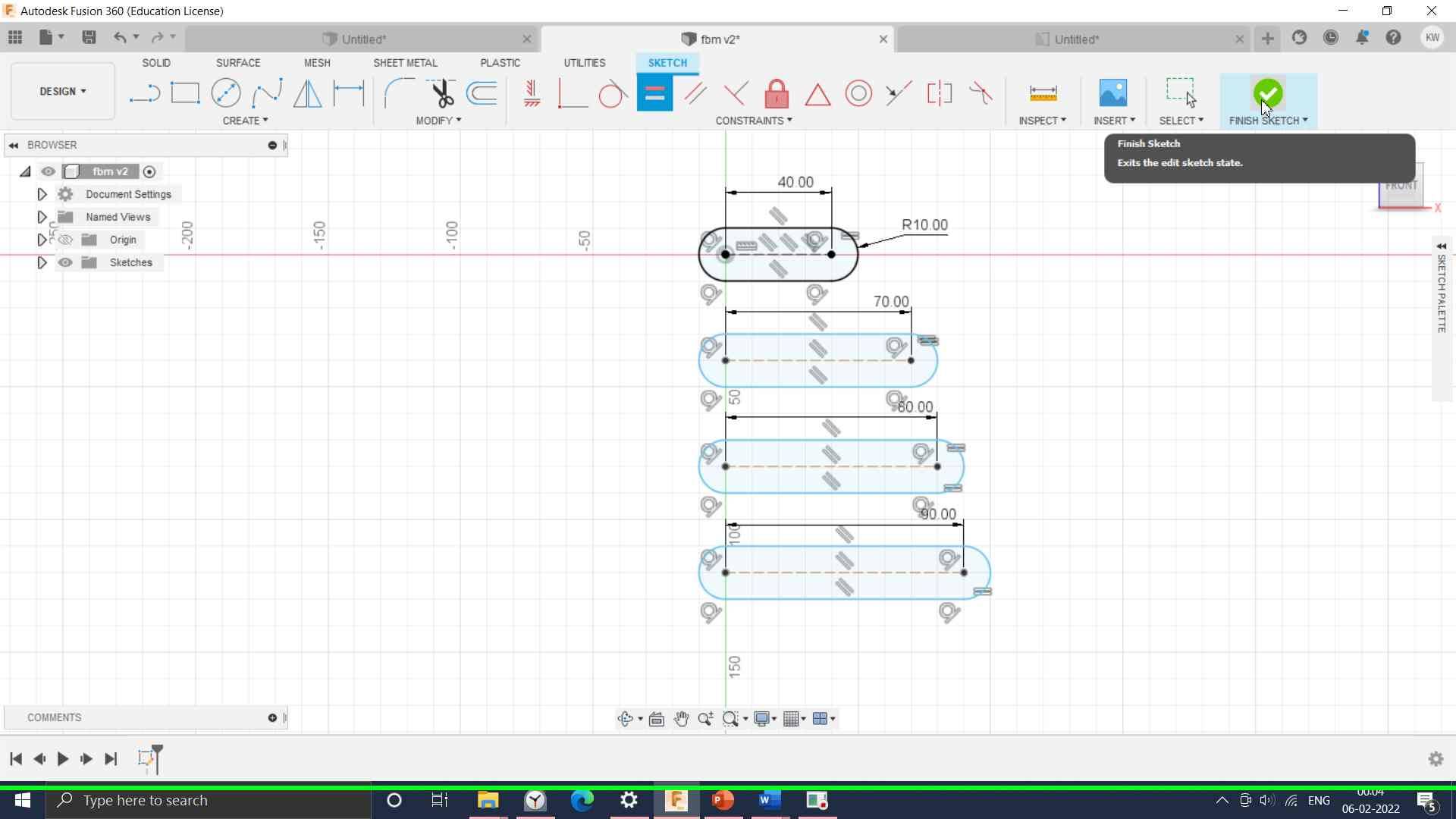
Started with the sketch tool and selected front plane.
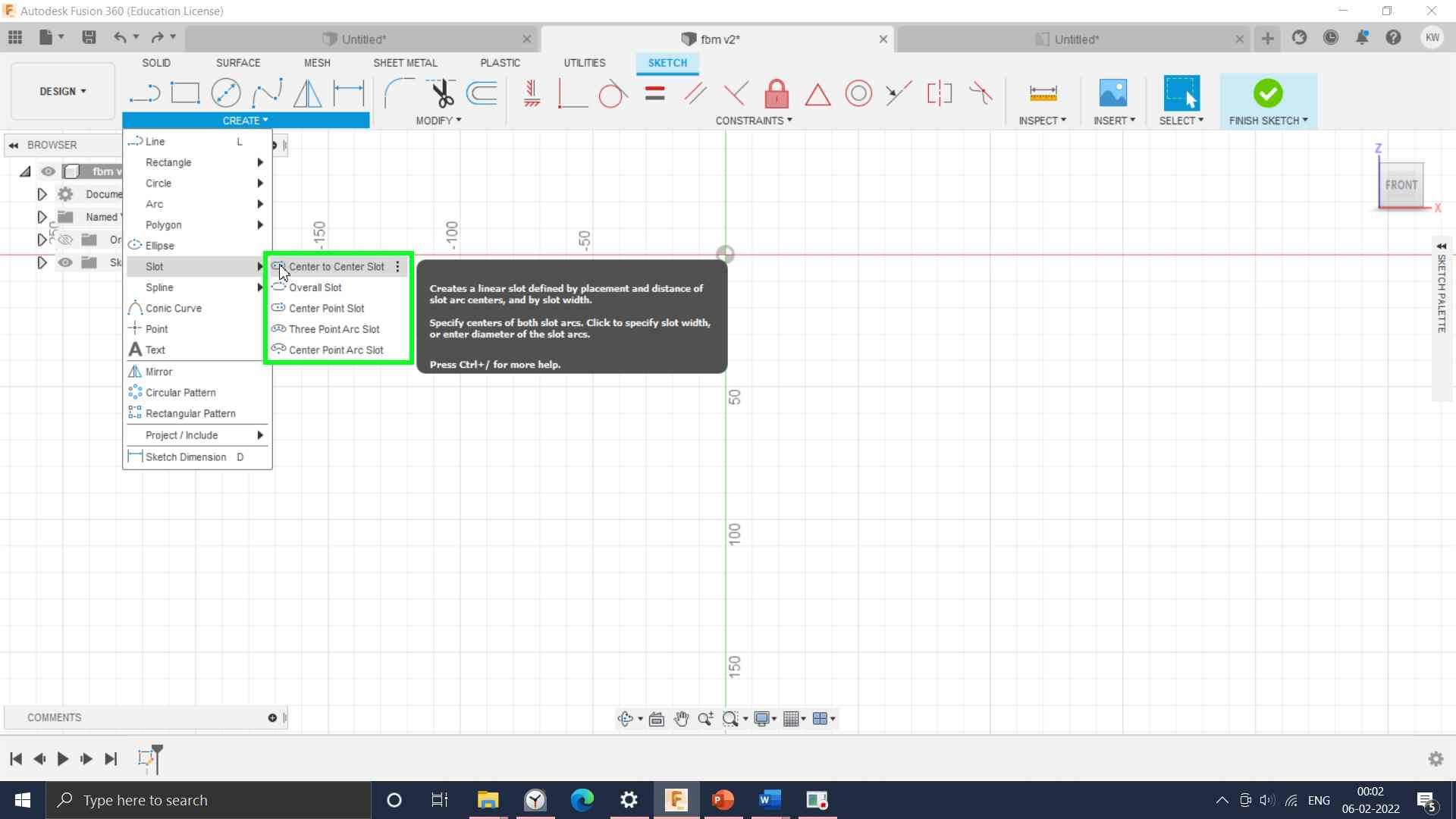
Selected slot tool to create a link
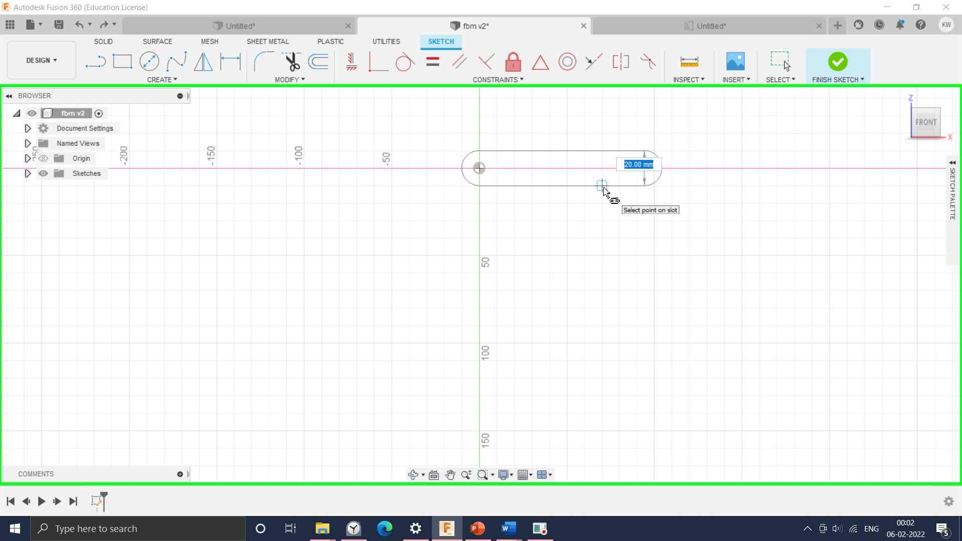
Four links drawn of different link length as shown.
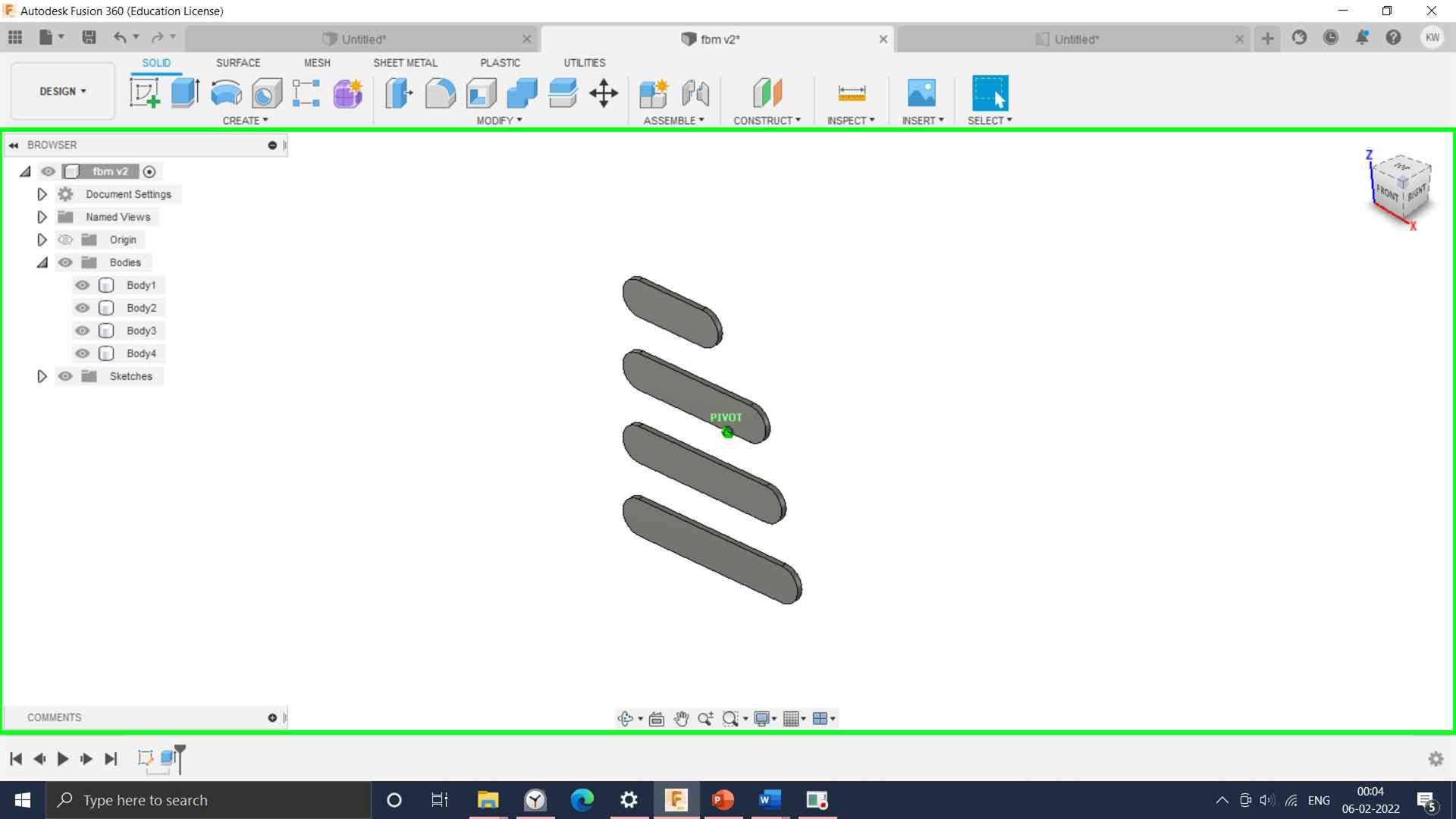
Then extrude feature was used to boss the sketch.
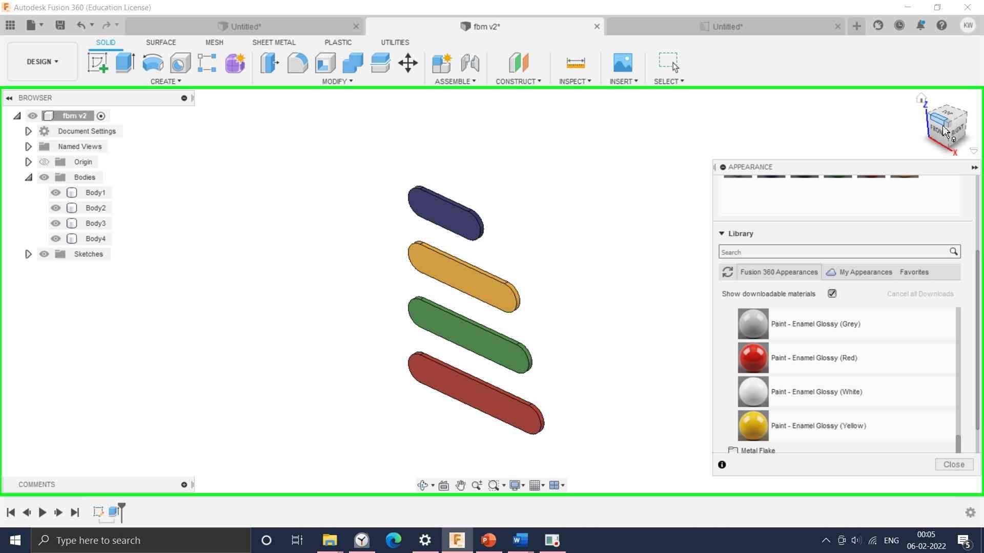
Assign the different color codes to the link.
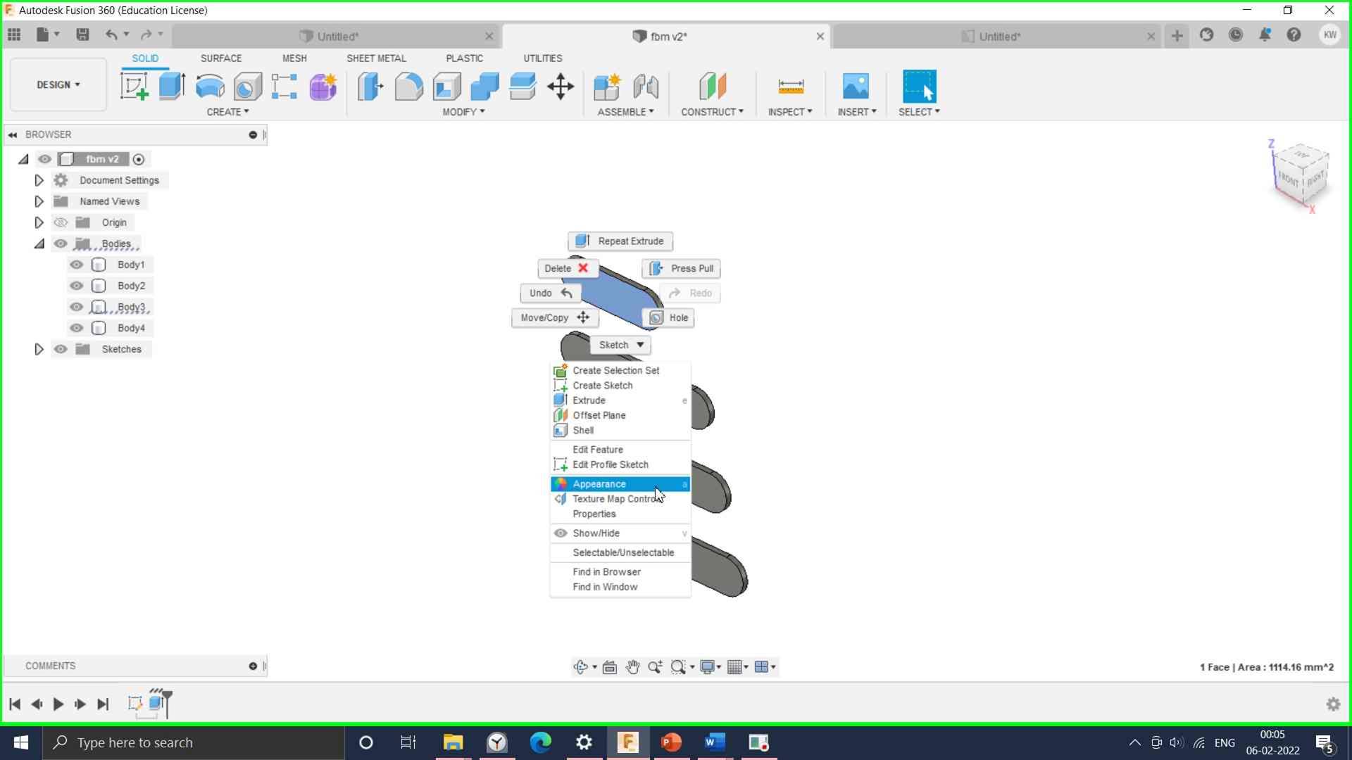
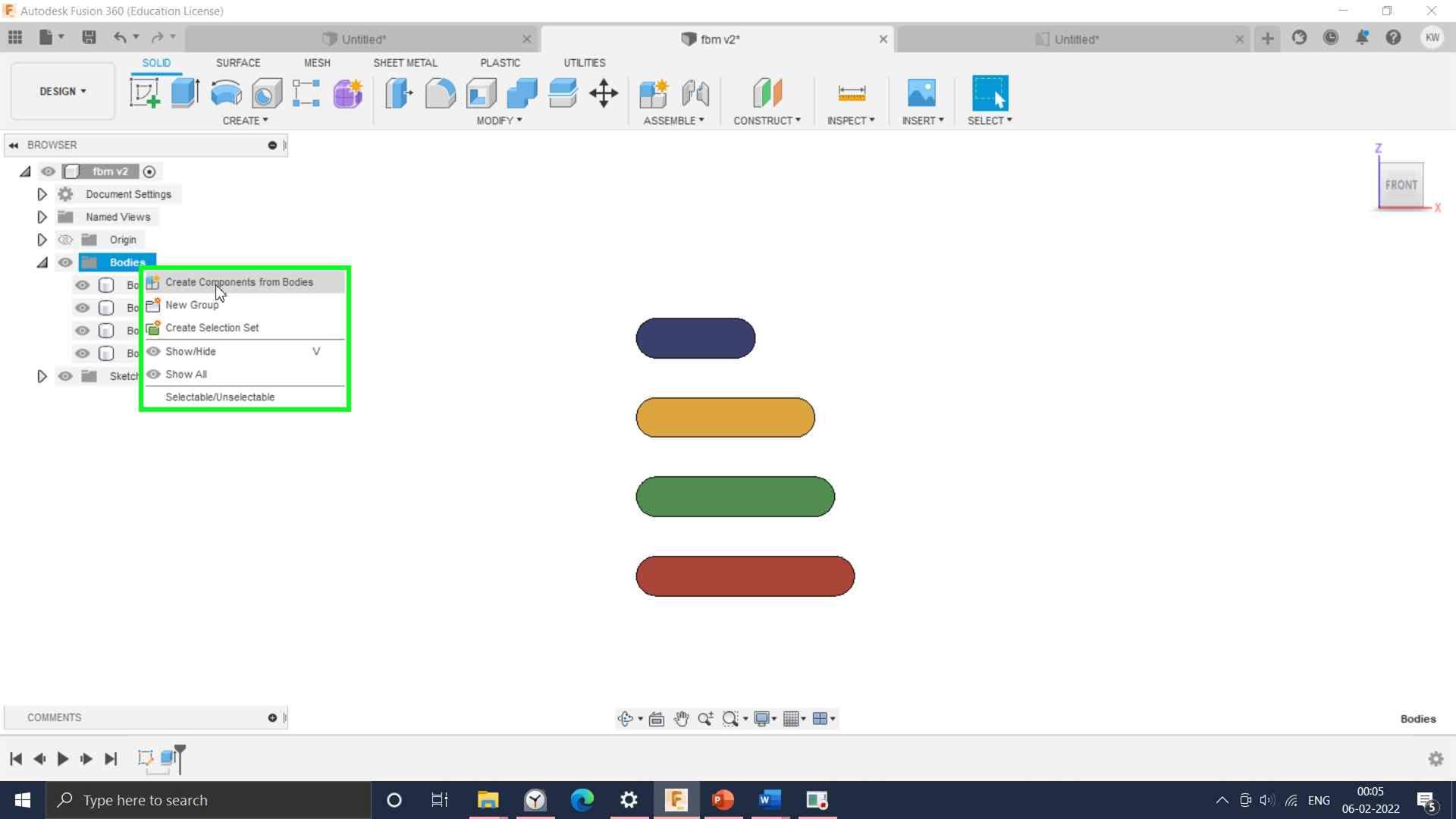
these links are drawn in single sketch, to make them separate parts, create components feature was used, so 4 different components are created.
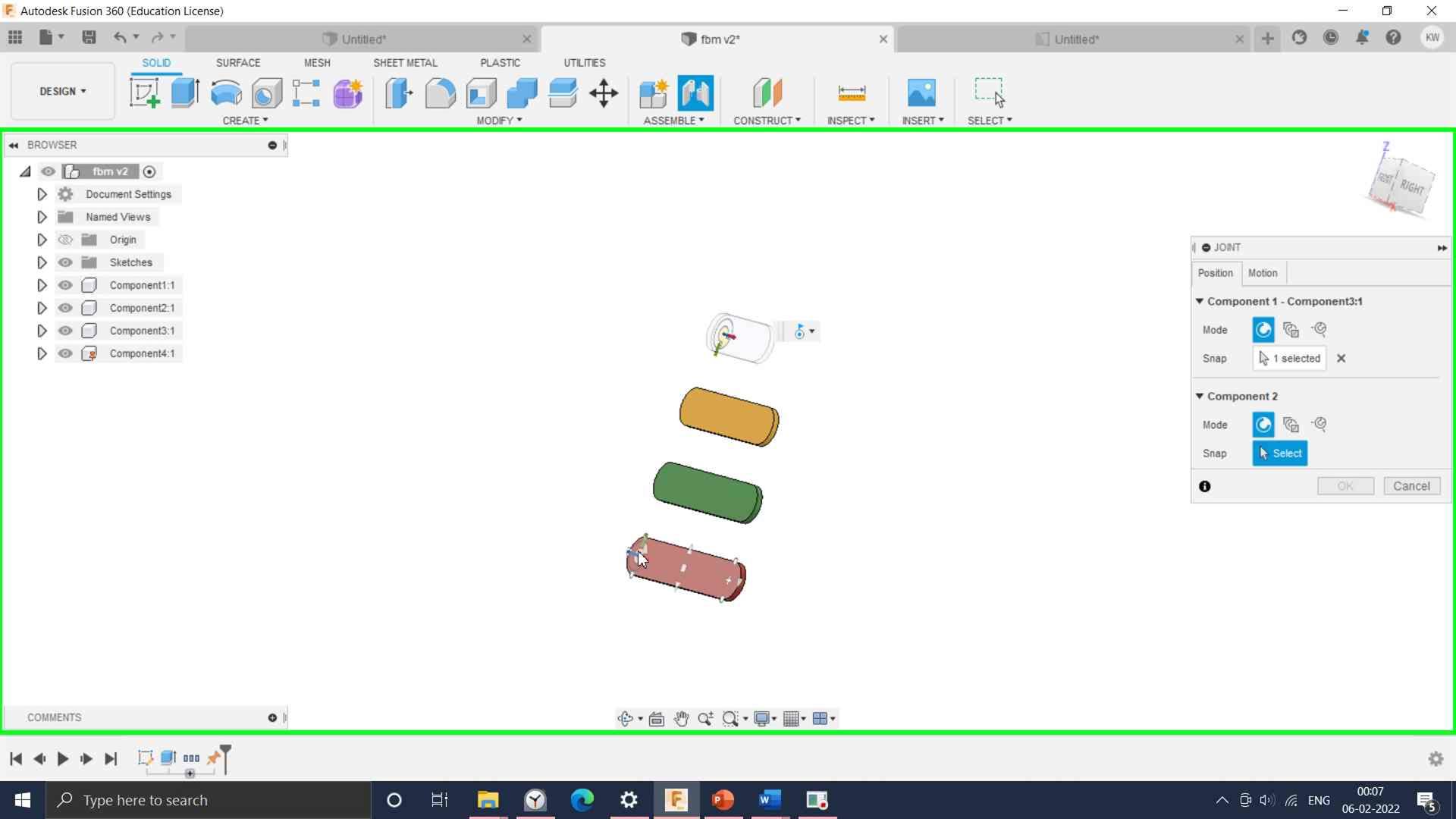
Red link is grounded makes revolute pair with blue link using joint feature
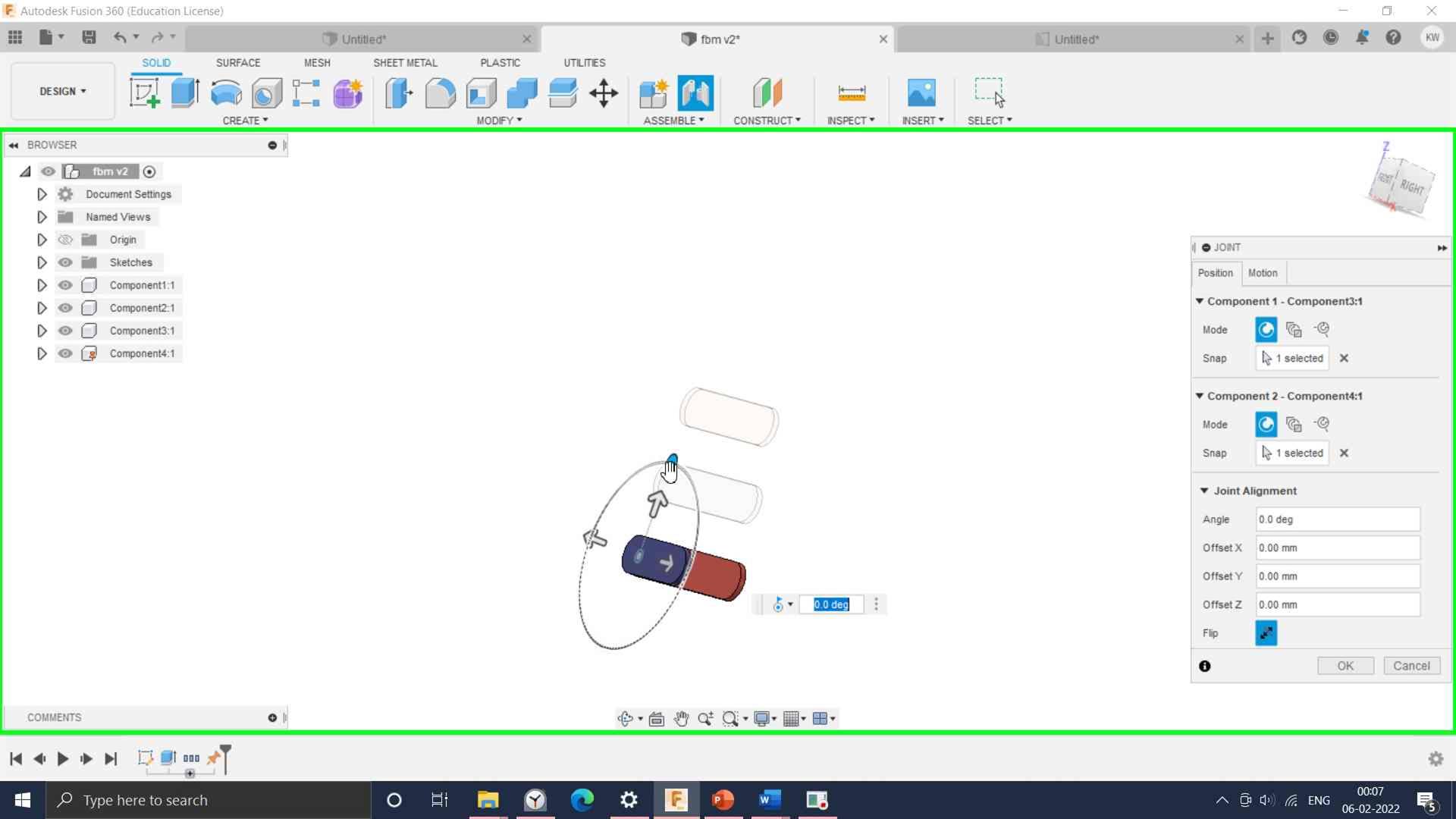
By forming a chain with revolute pairs and first link is connected to the last link.
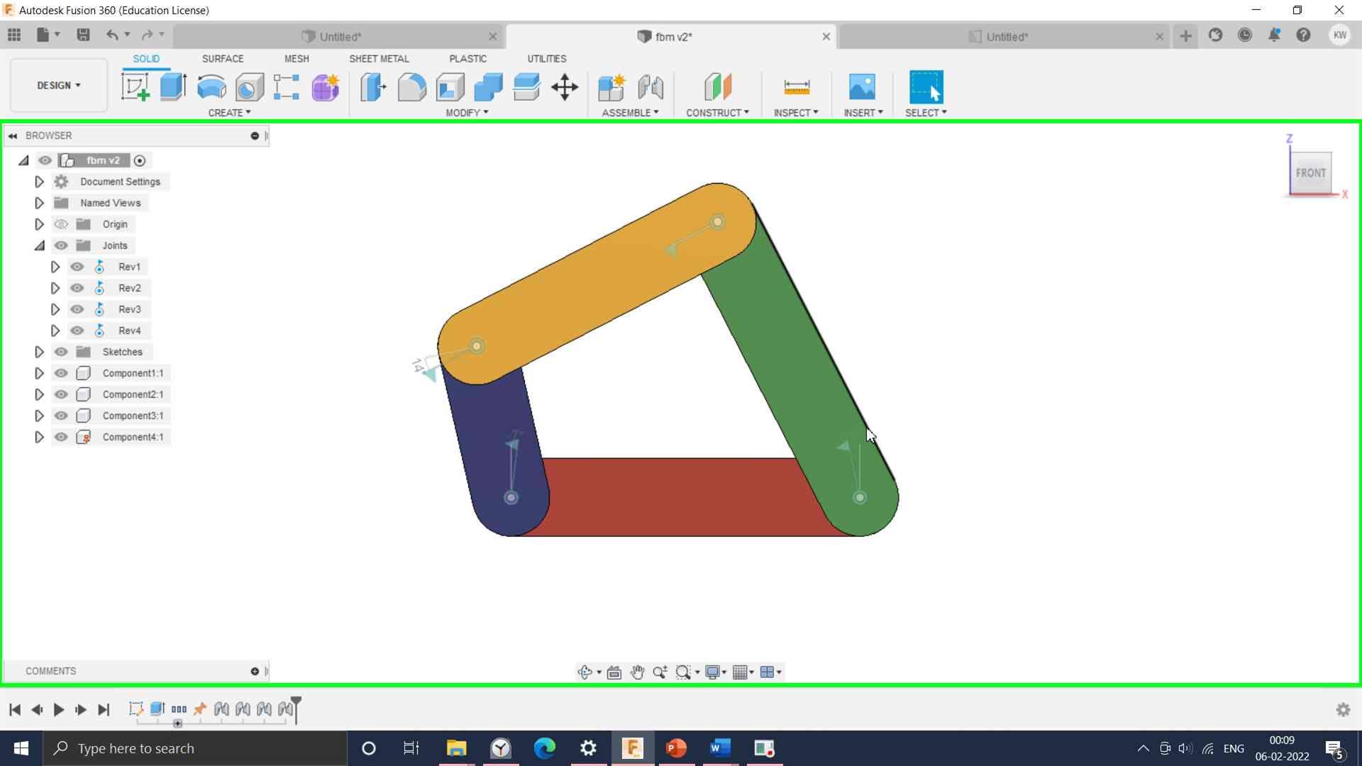
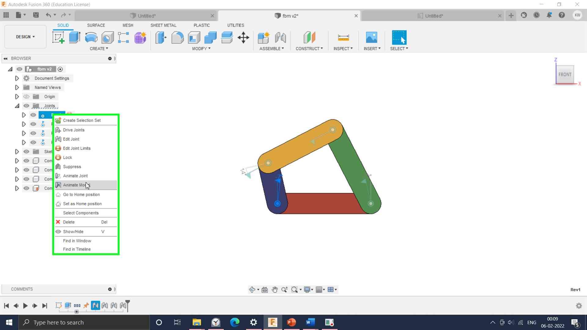
Joint between input link and fixed link is animated by selecting joint and click on Animate model.
And a short video to showcase it use:
3. Onshape
Onshape is a cloud-based CAD package with a simple GUI. It was a pleasant experience to work on Onshape.
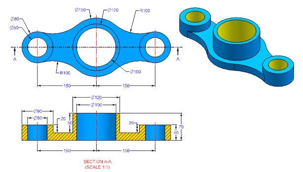
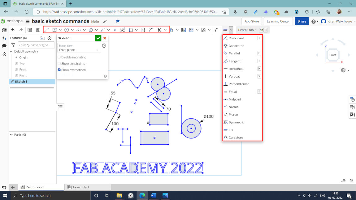
I have started with basic drawing commands and constraints in a software tool. Then I downloaded a part drawing to develop a 3D model.
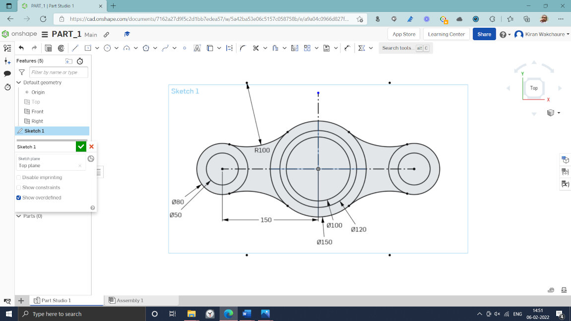
Read and understand the initial sketch.
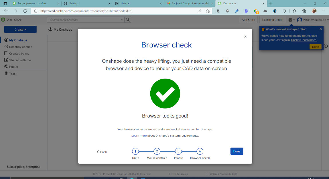
I am first time handling Onshape software. I have setup the browser for the Onshape software
Then I have learn how to use constraints in the sketch, which are very important and saves lot of time of designer.
Then I have drawn the sketch as per the dimensions.
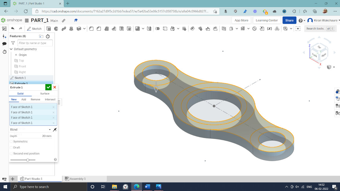
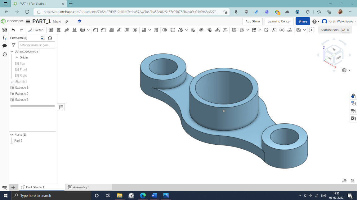
Then extruded different segments of the sketch to get required shape. And I have finished the Onshape modelling.
Final 3D Model
Audio / Video Editing
1. OBS Studio
1. OBS Studio 1
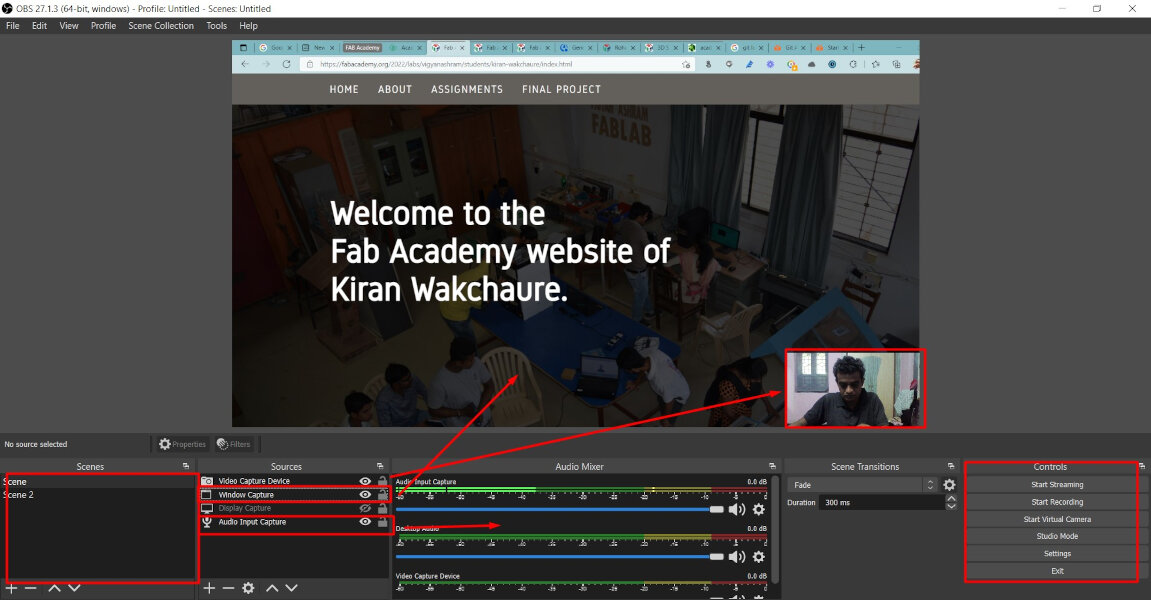
I have used OBS studio to capture the videos of software assignments. OBS Studio is a free, open-source, and cross-platform screen casting and streaming app.
GUI of OBS Studio
2. FFMPEG- Video Processing
FFMPEG is a free and open-source software project consisting of a suite of libraries and programs for handling video, audio, and other multimedia files and streams.
Software is used to compress the video files.Required file stored in ffmpeg folder in /c drive.
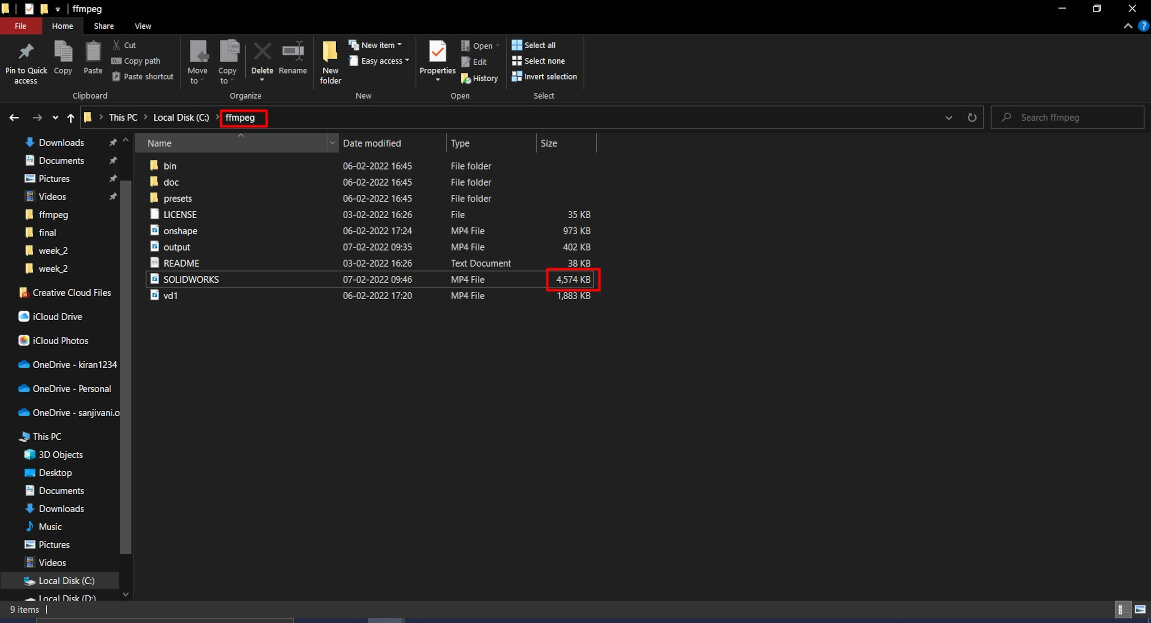
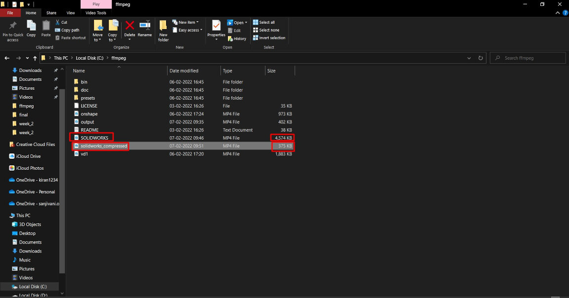
Then command prompt is opened in the ffmpeg folder and following command was used to compress the file. ffmpeg -i solidworks.mp4 -c:v libx264 -crf 25 -preset slow solidworks_compressed.mp4
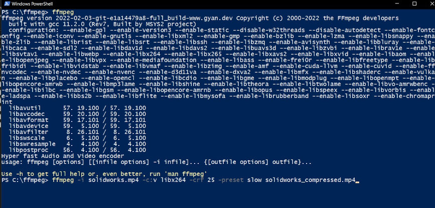
Figure shows 4.7 mb file is converted in to 375 KB.
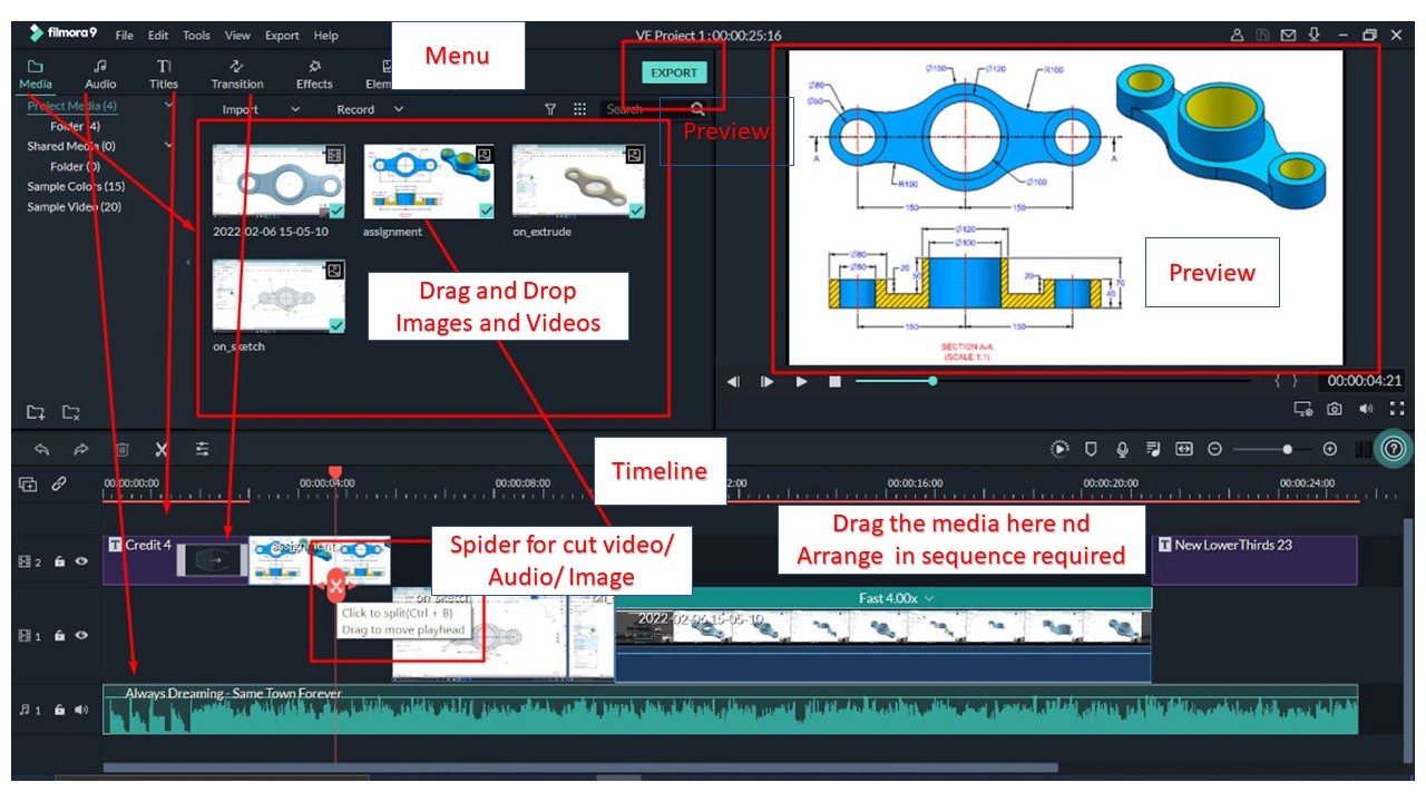
2. Filmora - Video Editing
For Video and Audio editing I have used Filmora tool. This tool is easy to use. So I stared with it.
Here I have recorded software video with OBS studio, edited with Filmora tool.
GUI of Filmora Tool
Downloads
3D Modelling .STL file can be download here.