Objective
Make an in-circuit programmer that includes a microcontroller:
Test it to verify that it works
Introduction
In this class we were introduced to different terms used in electronics production and were encouraged to build or fabricate a programmer.
This would be used in a future project to program our own boards. We were introduced to ISPs JTAG etc.
PCB Fabrication
PCB fabrication is one of the complex processes in electronics production.
There a couple of industries which alone do business on this aspect alone.
Eg. JLCPCB, Hon Hei electronics Ltd etc.
In fact the Govt of India has also announced a PLI (Production Linked Incentive) for this industry.
The links of the scheme will be hereif you wanna check it out.
There are two types of pcb fabrication processes they are listed below.
1. Etching
2. Milling
Though the latter one is more popular amongst hobbists and tinkers.
Etching is widely used process when it comes to batch or mass production in large industries.
Etching
PCB etching is the process of removing copper from a circuit board layer that is not protected by the hardened photoresist by immersing it in a chemical solution.
The chemical used to remove copper from the board is known as an etchant one of the main etchant that I know is ferric chloride.
More often industries have a very sophisticated system setup to dispose the residual or chemicals in their factories.
Hence its not recommended to perform etching at a residential place because the chemicals involved in the process are corrorsive and can caused plumbing issues if not disposed properly.
PCB Material
Fr 1 Copper Board 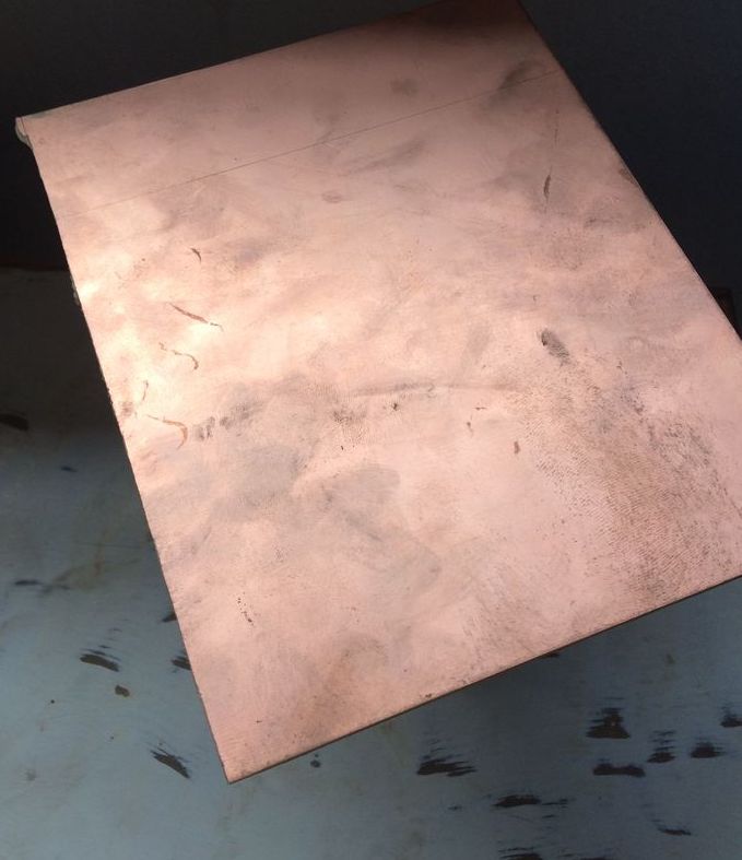
Etchant
Photoresist chemicals
Advantages of Chemical Etching
Etching is used in industries for mass production of PCBs
It has a very low-cost of tooling
Its Burr and Stress free
Offers flexibility
Supports a wide range of material grades.
Source:- Precision micro
Limitations of Chemical Etching
Chemical etching has its downsides also like:-
It requies special chemicals that are costly and requires special methods to store these.
It needes specialized machines and equipment.
Proper infrasture is setup is needed.
Requires a clean Room and a Dark Room.
Requires specific wavelengths of light for etching purposes.
Machining or PCB milling
In the lab we used an SRM-20 PCB miling machine to trace and cut an electronic circuit.
The image shown below is a SRM-20 PCB milling machine.
Incase if anyone wants detailed instructions about the machine then I'm leaving a download link to the user manual.

The parts for the machine are listed below
1. Bed
2. Sacrificial Layer
3. FR 1 Board
4. Collet and grub screw
5. Spindle
6. Allenkey
7.Splatula
To mill my own ISP first I started by refering to Brian's design the documentation the Brian has provided is good enough that I could understand the ins and outs of electronic production.
After finding the design I used modsproject to create the .rml files.
The first RML file that we create should be a trace file using 1/64 end mill.
Second file should be given for a cut function using 1/32 end mill.
After that Use Vpanel (The software used to control SRM-20) to control the milling machine.
Loosen the grub screw in the collet to insert the 1/64 end mill to trace the pcb.
Set your desired xy axis position using VPanel.
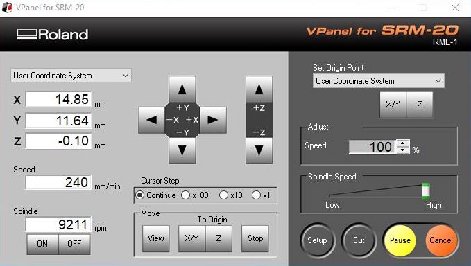 Interface of Vpanel
Then set the origin for Z-axis by lowering the Z-axis near to the Fibre glass board but a few mills above and perform a gravity by loosening the grub screw. This process only comes by practice I'll will be posting a video down below for showing gravity.
Tighten the grub screw set the z axis and lift the z axis to a safe distance before milling and then click the cut button.
Then select your trace.rml file to mill the PCB and then milling will begin if you find and abnormality like origin issues or too much travelling time on before milling then check your mods file and search for problem there and create the correct file.
End Mill
Different types of end mills
There are various types of endmills that are used for milling we will be dicussing only 3 of these they are:-
1/32"
1/64"
1/100"
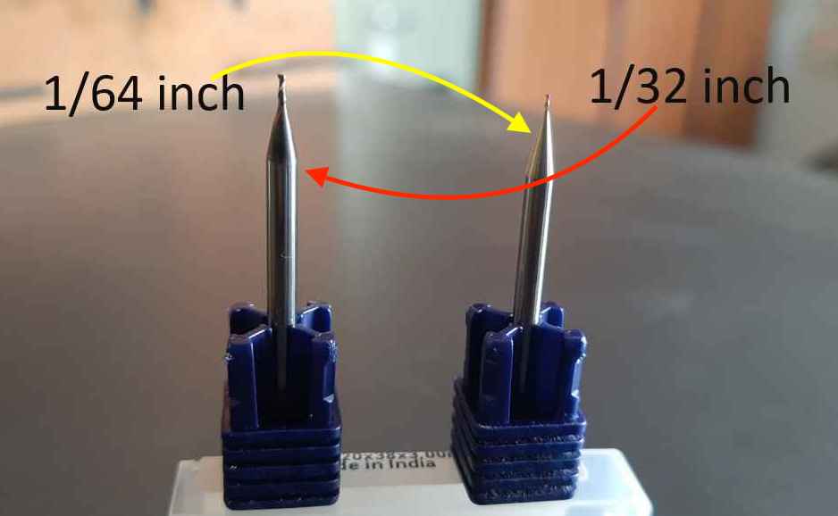
1/32"
Its an end mill thicker than the 1/64" end mill. It is used for deeper cut.
The main purpose of this endmill is to cut the PCB in the desired shape on the SRM-20.
1/64"
Its used to mill PCBs we can mill a trace of almost 16 mills with this end mill.
Since it thinner than the 1/32 end mill the tool life of this end mill is also almost half. At max we can only mill 20 PCBs with this end mill.
The number 20 is just an estimate and not the maximum since it depends on the user and for the task that he/she is using this end mill.
1/100"
Its the thinnest of all other end mills. The tool life of this end mill is lower than that of the 1/64 ones. The advantage of having thses is that we can mill traces smaller than 16 mills.
I guess the smallest trace that it can mill is 6 mills but I'm not sure.
Advantages of PCB Milling
Compared to chemical etching PCB milling is an easy process
It can be done by a DIY hobbiyist at home or in a well lit environment.
Less amount of waste is produced i the process compared to chemical etching.
Waste disposal is easier.
The less specialised equipment is used in this process
It is possible to produce low cost low quantity PCB through milling.
Limitations of PCB Milling
Chances of Burr and stress after milling
Limited grades of material
PCB milling is limited to the bed dimension
Milling quality and capability is dependent on the tool used smaller diameter tools can mill precisely.
Usage of ModsProject and the things in between before milling a PCB.
Lets dive into a bit of the software side I used modsproject to mill my PCB.
Mods project is a bowser based software developed at Centre for Bits and Atoms.
The application is used for variuos purposes one of the applications its used for is for generating RML files for PCB milling.
An image below showing the modsproject interface.
Start by uploading a jpeg image of the PCB i.e an inner cut image then select the desired endmill and play with the settings a bit.
Togglr the Save switch to save the rml file the click Calculate.
The RML file will be downloaded automatically to your folder.
Perform the same action with outter cut image remember ti change the end mill settings also.
Soldering
Soldering iron
RoHS
RoHS is a compliance standard introduced by the EU. It restricts hazardous chemicals in electrical and electronics equipment. The abbreviation is "Restriction of Hazardous Substances.
One of the resticed materials in this standard is Lead (Pb) because of its hazardous nature on living organisms.
Soldering Workstation
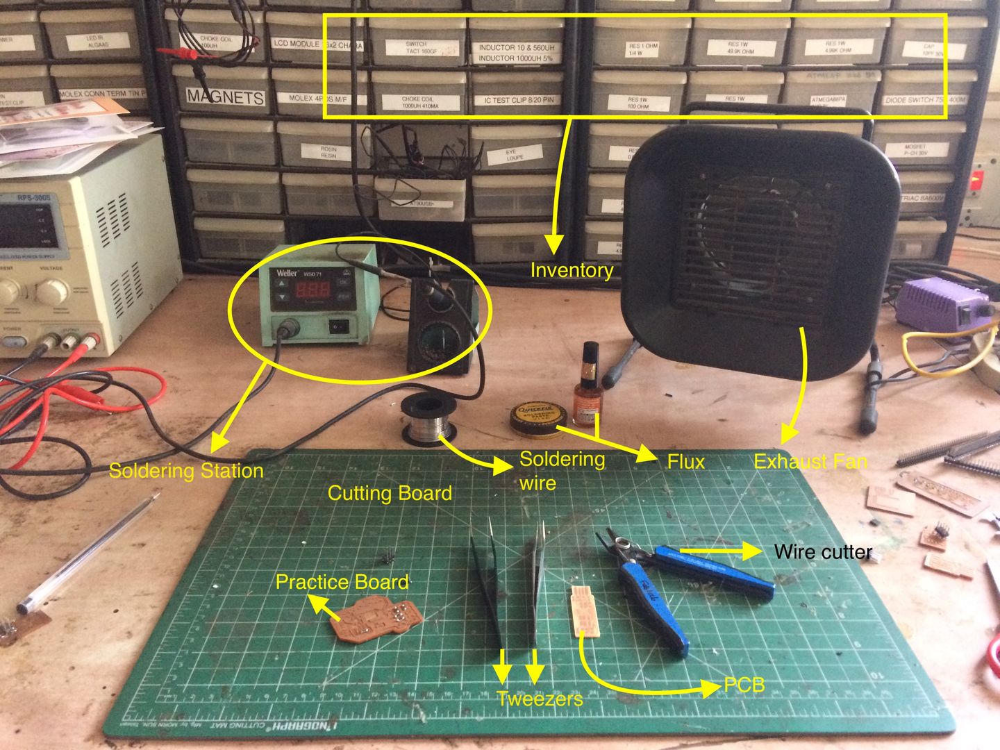
A soldering working station is used to solder different components on a PCB in house. There are various equipments needed to perform soldering.
The image below show a soldering workstation and the different tools that can be found to solder different components
How did I solder?
Padding and Stuffing
The process of soldering components on to a PCB is known as stuffing.
Stuffing is conmmon process that done both industrially and by hobbiyist alike with the help of pick and place robots or manulally.
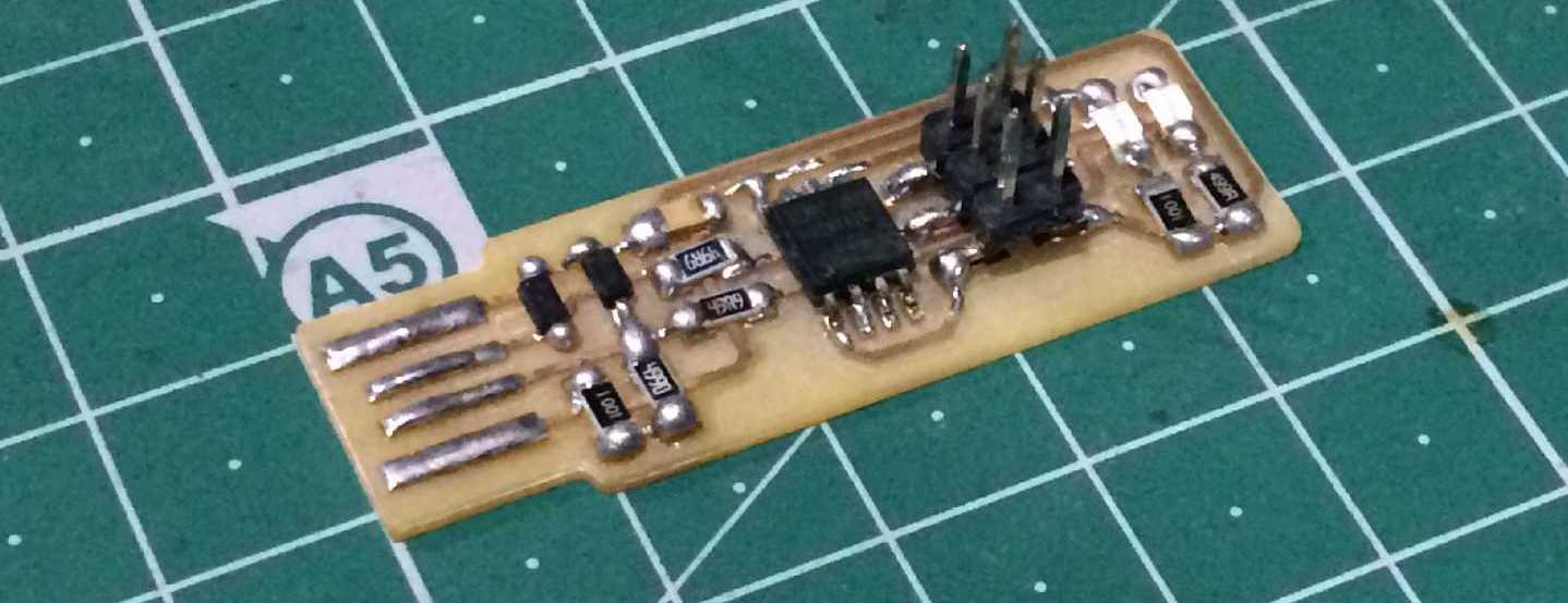
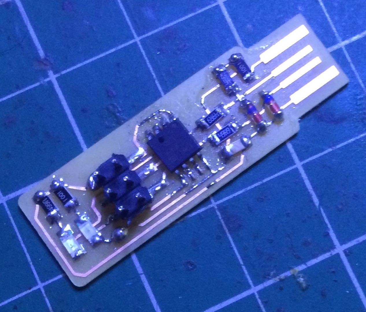
The image below shows the components stuffed manually by hand on to a pcb to form a programming circuit.
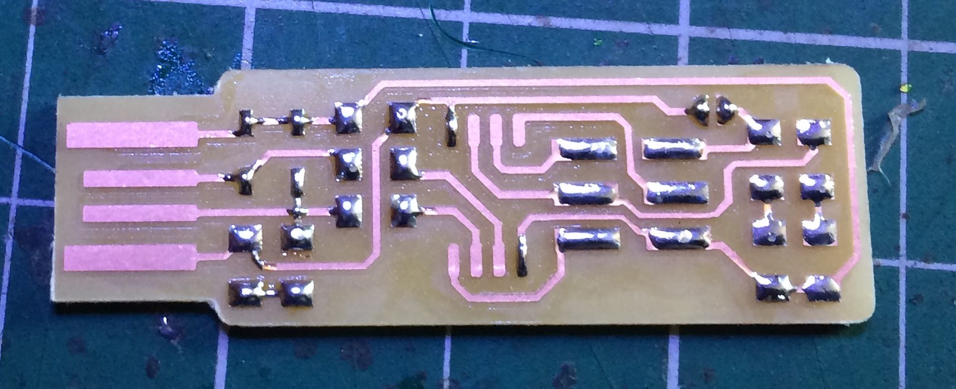
The picture below shows padding.
After milling the ISP I checked the components that I want to stuff on the board. Then I padded the board with some solder as shown in the image below.
Stuffing a board has to be done carefully if not done with care and precision we might end up with an rc-1 error (basically an connection error).
The picture below shows stuffing of componenets.
Programming your ISP
Soldering and Debugging your ISP is half of the job we have to program the ISP that we have stuffed.
Programming the ISP depends on the OS that you are using, its possible through Windows,MacOS and Linux.
The easiest way to program an ISP is using linux.
We have to install a software called AVRDUDE. This software allows us to program an ISP or burn bootloader to the chip.
In Arduino IDE if we click the "Burn Bootloader" option in the "Tool" tab then this software works in the background and burns bootloader to the chip.
Why are we programming the ISP?
Ans:- In a ISP we used a chip called Attiny 45. The reason to use this chip is because we have a couple of these in stock plus the semiconductor shortage has caused a lot of problem to procure other SMD components.
Ok these chip don't come pre-programmed from the foundary thats the reason why we burn the bootloader to this chip. A bootloader contains basic but crucial information of a chip. For starters it contains the Name of the chip we are using the the CPU clock frequency and other related information.
I'm attching some images below for the steps to be followed in the computer to program an isp using AVRDUDE.
Setting up the IDE
Below shows the commands needed to set up the IDE and tools like AVRDUDE.
$ brew install avrdude
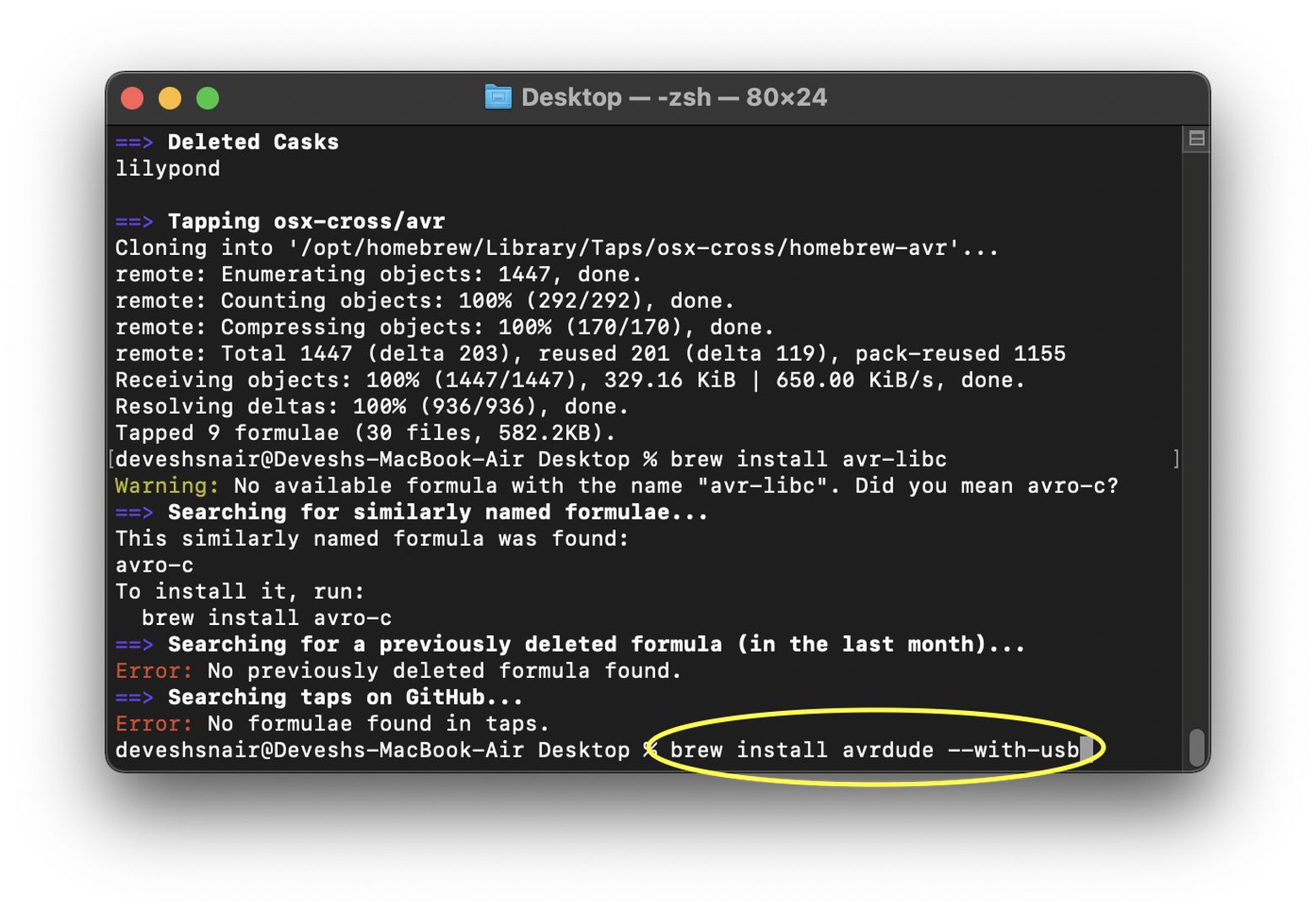
$ brew tap osx-cross/avr
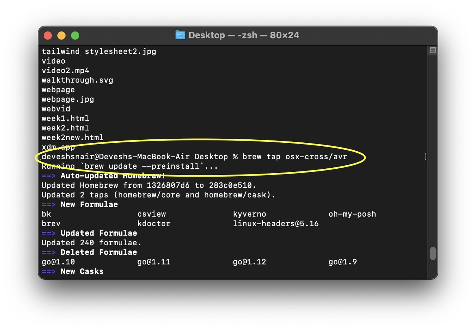
$ brew install avr-gcc
$ brew search avr
$ brew update
Installing Crosspack
Goto Crosspack website with the given link below and download the package.
Crosspack
The file will be a .dmg file which graphically installs crosspack to the Mac. For your infor I'm currently using MacOS 12 and the software works fine on the newer M1 based macs.
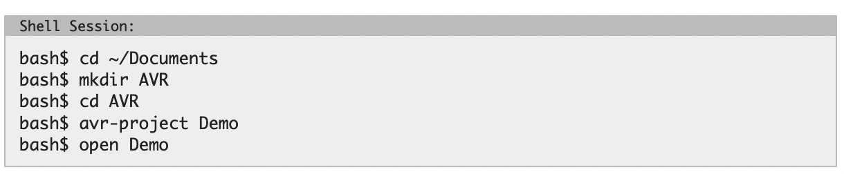
After the installation of Crosspack goto open your Terminal window and type the following command.
cd Desktop
Then follow the steps given in the image below.
Download the firmware folder from the link given below.
firmware
Uncompress the zip file and copy the contents present in it.
Locate the firmware folder in the Demo directory and delete the contents present in it.
Then paste the contents that you previously copied into this folder.
Now type open a termina window of the Demo directory and cd into firmware.
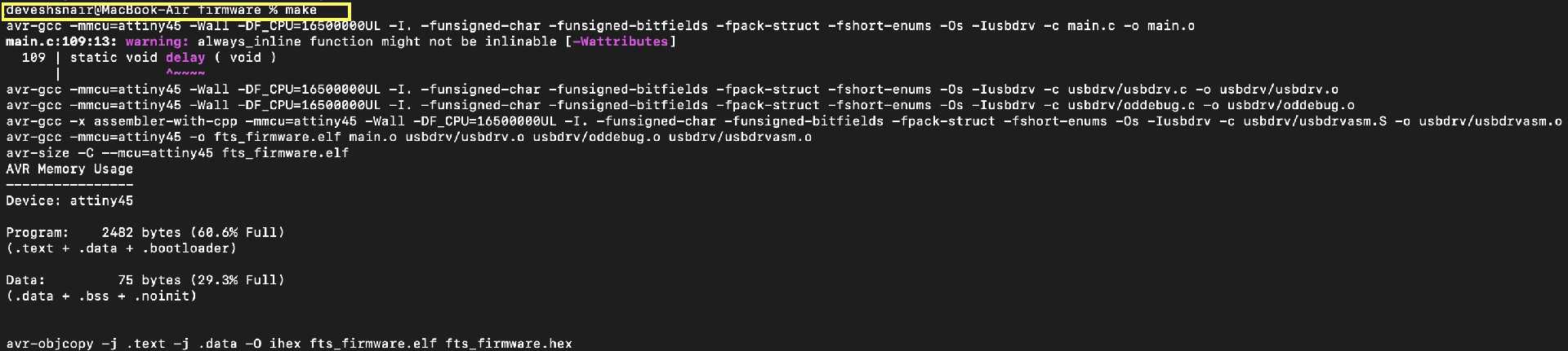
Then type the command "make".
This will build the firmware with a .hex file in the firmware.hex
The image shown below will give you an idea.
After seeing a result something similar above. Type "make flash" command.
This will erase any contents on the target chip something like flashing the memory.
The image for which is shown below.
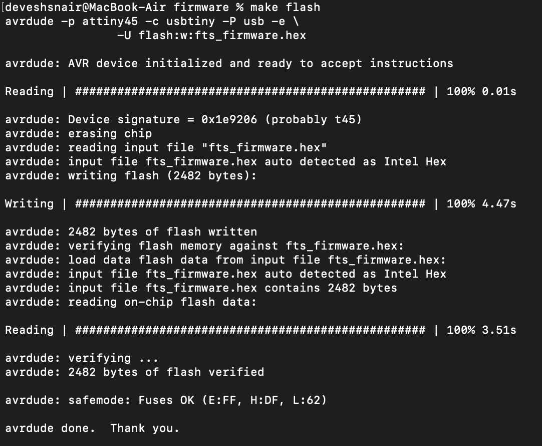
make flash command at the hardware level green leds blink.
 Source:- Flash
After this type command "make fuses" to burn the bootloader. The result is shown below.
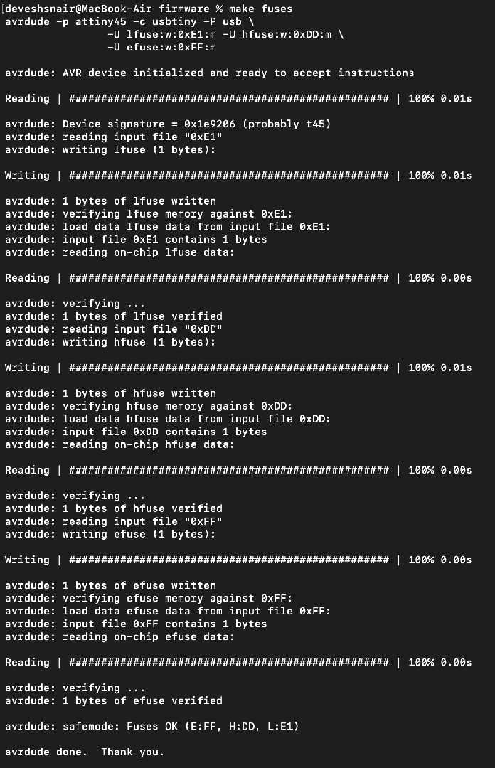
Vola! the bootloader is burnt to the chip but there is one mor step.
You see the bootloader isn't persistent to the chip right now it can be flashed again so if ypu wanna create a programmer of your own the chage should be permanent and this is done by disabling the reset pin.
Therefore type the command "rstdisbl" to disable the flash from being burnt again and again.
There you have it now your FabISP is ready. Just program other boards with it to make is usefull.
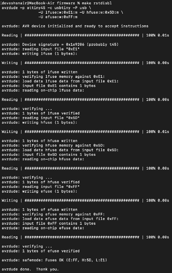
After this type command "make rstdisbl" to disable the reset pin and make the program persistent on the IC.
The image below shows the uasge of the command.
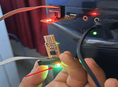
To check the ISP is working tin the USB pads then stick the ISP into the computer and check the device manager
Here I will be showing the same thing for a mac in the image below.
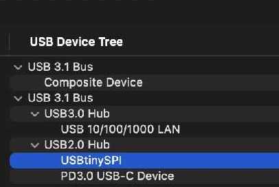
If the ISP shows itself as "USBtiny" then the ISP is working fine just program other ISPs or Hello World boards to put it into good use.
note:- If this error occurs while make command "make: avr-gcc: Bad CPU type in executable"
Then use "brew install avr-gcc" in the Demo folder.
note:- The makefile present in the firmware folder is set by default to program attiny usb please make changes to it if you are using a different IC while creating a different programmer other than a FabISP.
My Experience
The experience with soldering different surface mount components was a bit rough. In the first try it almost 3 hrs for me to solder the IC itself all the other components were easier to solder with a exception on Zener Diode.
Check my recommendation section for tip that I applied during this week.
How to place your ics
First place your IC on the pads and then start by soldering from the corners and then solder all other pads. After which it should be easier to solder the IC
Debugging
The rc -1 error
If we get an rc-1 error then try these steps to debug the board.
First check the connections of your board.
Then check the ribbon cable that you have connected it could be the culprit.
Do a continuity check on the board make sure that all the components are connected.
Check the components regularly there might be an issue with the external clock you might be using or change the IC that is on the board.
Check if the components are not shorted.
Resolder your connections.
Hold down on the IC while programming this was one of the solutions that helped me program my ISP and my hello world board.
Video
Below I'm attching a video to show that the ISP is programming my hello world board.
Group Assignment
This week for our group assignment we studied the design rules of our PCB milling machines and various aspects of electronics production.
Use the link to check to group assignment.
We were just checking how many smaller trces can be milled by the 1/64 end mill. All the experimenting and other things were documented on the group assignment page to visit it click here.
References
Debugging and Crosspack issues.
Brian Page

Fabspace by Devesh S Nair is licensed under a Creative Commons Attribution-NonCommercial 4.0 International License.