This week we had to create interfaces to our boards using serial communication. I decided to use ![]() Python to do that.
Python to do that.
The board I used is my HEXI_03 Board that I built in Input Devices Week.
Learning:
- Group Assignment
- Processing
- MIT APP INVENTOR
- Python3 (jupyter)
- Individual Assignment
- #Connect to your board
- #Interface Arduino UNO with Ultrasonic Sensor
-
MIT App Inventor
-
HEXI_03
Group Assignments

Processing is a versatile software sketchbook and a programming language for learning how to code in the visual arts. Processing has been promoting software literacy in the visual arts and visual literacy in technology since 2001. Processing is used for learning and prototyping by tens of thousands of students, artists, designers, researchers, and hobbyists.


MIT App Inventor is a web application integrated development environment originally provided by Google, and now maintained by the Massachusetts Institute of Technology.


JupyterLab is the most recent interactive development environment for notebooks, code, and data that is available on the web. Users may create and arrange workflows in data science, scientific computing, computational journalism, and machine learning using its versatile interface. Extensions to enhance and enrich functionality are encouraged by a modular architecture.
The benefits of utilizing jupyter include its resemblance to HTML and the ease with which strong data visualization tools like seaborn and matplotlib, as well as scientific libraries like NumPy, may be used. And the greatest part is that if you understand the fundamentals, it's pretty simple to put it together.

Individual Assignments
Our instructor Adriana has linked us with her colleague Marcello Tania, as he is the instructor in the Blue Lab 
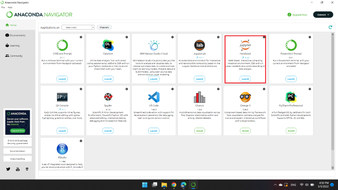
First thing in this week is to choose an IDE for the Python language; So, we downloaded 

Then we launched ![]()
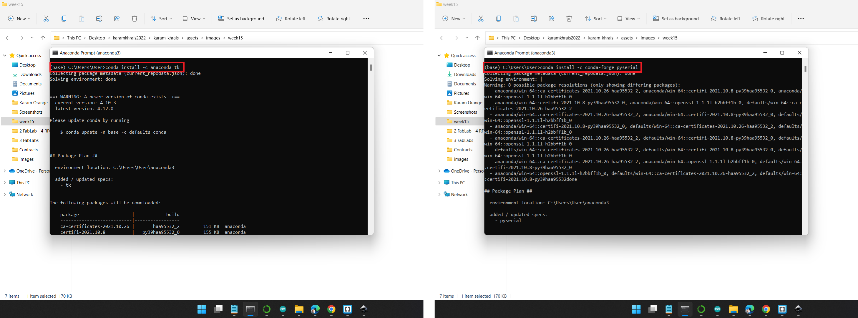
Next, I Installed 2 libraries: Tkinter and Pyserial.
From Anaconda Prompt:
-
User Interfaces: conda install -c anaconda tk
Device Interfaces: conda install -c conda-forge pyserial
We followed this tutorial to learn Python, it's amazing from Marcello!
#Connect to your board
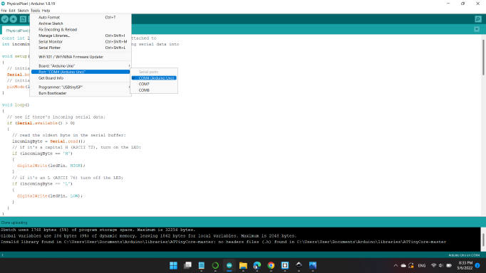
One important example is to connect the board (Arduino).
A GUI for controlling an LED.
Example, 04.Communication, PhyscialPixel
Arduino Code
                    const int ledPin = 13; // the pin that the LED is attached to
                    int incomingByte;      // a variable to read incoming serial data into

                    void setup()
                    {
                      // initialize serial communication:
                      Serial.begin(9600);
                      // initialize the LED pin as an output:
                      pinMode(ledPin, OUTPUT);
                    }

                    void loop()
                    {
                      // see if there's incoming serial data:
                      if (Serial.available() > 0)
                      {
                        // read the oldest byte in the serial buffer:
                        incomingByte = Serial.read();
                        // if it's a capital H (ASCII 72), turn on the LED:
                        if (incomingByte == 'H')
                        {
                          digitalWrite(ledPin, HIGH);
                        }
                        // if it's an L (ASCII 76) turn off the LED:
                        if (incomingByte == 'L')
                        {
                          digitalWrite(ledPin, LOW);
                        }
                      }
                    }
Python Code
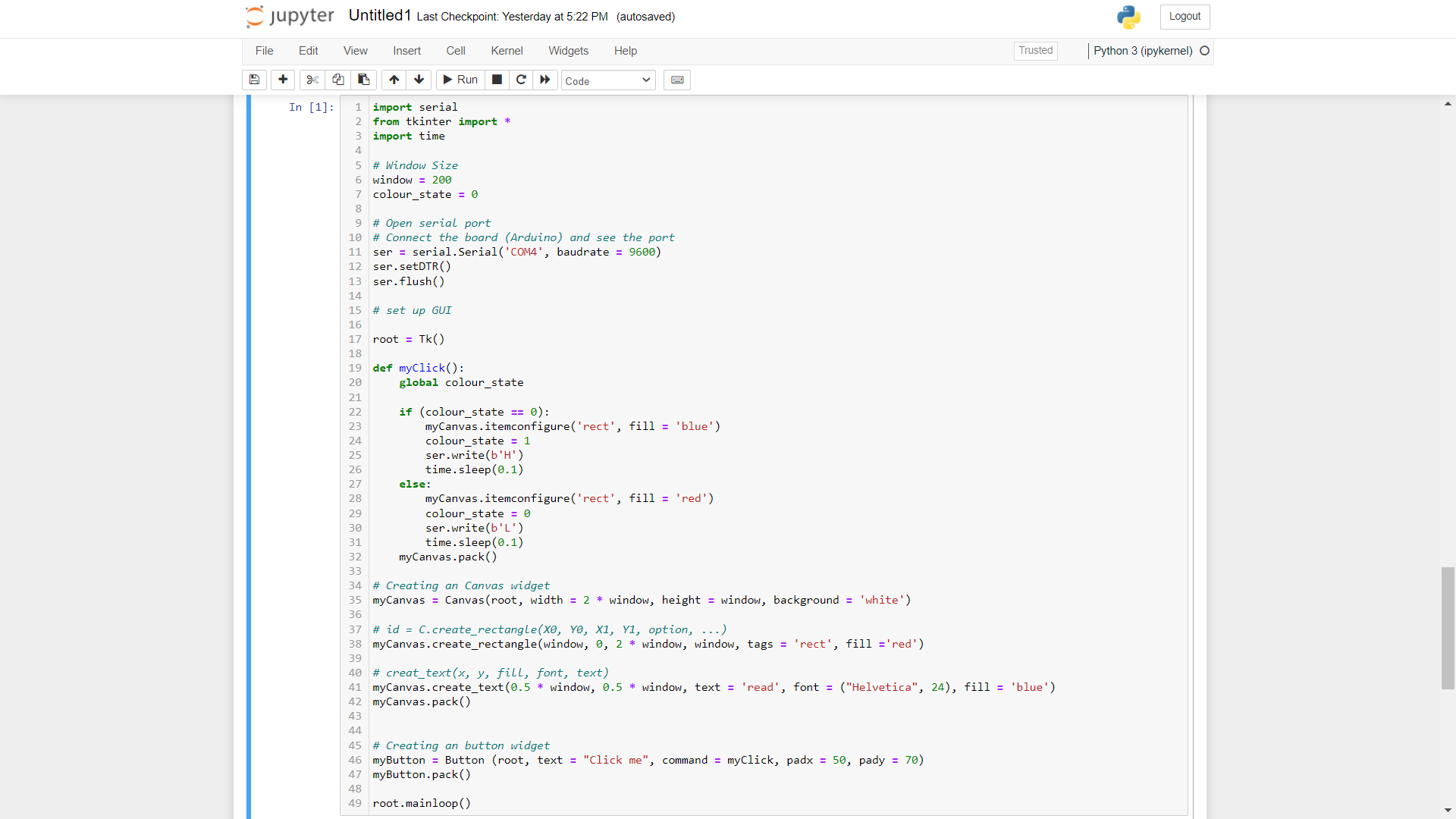
                    import serial
                    from tkinter import *
                    import time

                    # Window Size
                    window = 200
                    colour_state = 0

                    # Open serial port
                    # Connect the board (Arduino) and see the port
                    ser = serial.Serial('COM4', baudrate = 9600)
                    ser.setDTR()
                    ser.flush()

                    # set up GUI

                    root = Tk()

                    def myClick():
                        global colour_state

                        if (colour_state == 0):
                            myCanvas.itemconfigure('rect', fill = 'Orange')
                            colour_state = 1
                            ser.write(b'H')
                            time.sleep(0.1)
                        else:
                            myCanvas.itemconfigure('rect', fill = 'Gray')
                            colour_state = 0
                            ser.write(b'L')
                            time.sleep(0.1)
                        myCanvas.pack()

                    # Creating an Canvas widget
                    myCanvas = Canvas(root, width = 2 * window, height = window, background = 'white')

                    # id = C.create_rectangle(X0, Y0, X1, Y1, option, ...)
                    myCanvas.create_rectangle(window, 0, 2 * window, window, tags = 'rect', fill ='Gray')

                    # creat_text(x, y, fill, font, text)
                    myCanvas.create_text(0.5 * window, 0.5 * window, text = 'State', font = ("Helvetica", 24), fill = 'Black')
                    myCanvas.pack()


                    # Creating an button widget
                    myButton = Button (root, text = "Click me", command = myClick, padx = 50, pady = 70)
                    myButton.pack()

                    root.mainloop()
#Interface Arduino UNO with Ultrasonic Sensor
In the past two weeks in (Input Devices), I decided to use Ultrasonic Sensor to be used in my final project, so I decided to interface the sensor distance with the python code using Arduino UNO.
Arduino Code
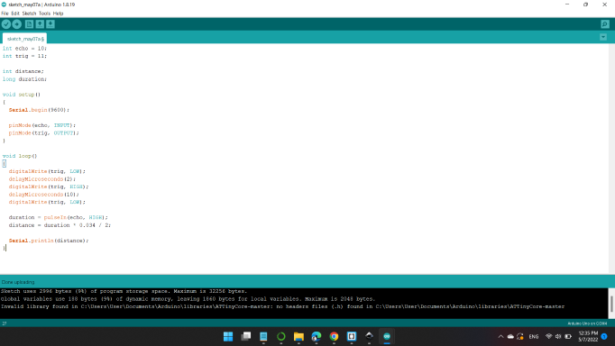
                    int echo = 10;
                    int trig = 11;

                    int distance;
                    long duration;

                    void setup()
                    {
                      Serial.begin(9600);

                      pinMode(echo, INPUT);
                      pinMode(trig, OUTPUT);
                    }

                    void loop()
                    {
                      digitalWrite(trig, LOW);
                      delayMicroseconds(2);
                      digitalWrite(trig, HIGH);
                      delayMicroseconds(10);
                      digitalWrite(trig, LOW);

                      duration = pulseIn(echo, HIGH);
                      distance = duration * 0.034 / 2;

                      Serial.println(distance);
                    }
Python Code
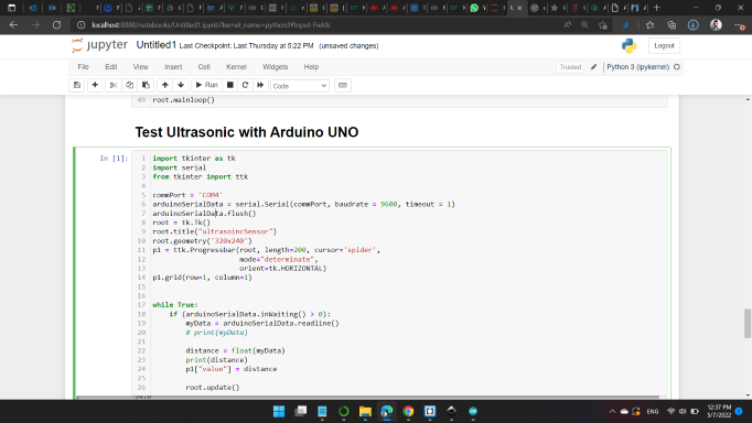
                    import tkinter as tk
                    import serial
                    from tkinter import ttk

                    commPort = 'COM4'
                    arduinoSerialData = serial.Serial(commPort, baudrate = 9600, timeout = 1)
                    arduinoSerialData.flush()
                    root = tk.Tk()
                    root.title("ultrasoincSensor")
                    root.geometry('320x240')
                    p1 = ttk.Progressbar(root, length=200, cursor='spider',
                                         mode="determinate",
                                         orient=tk.HORIZONTAL)
                    p1.grid(row=1, column=1)


                    while True:
                        if (arduinoSerialData.inWaiting() > 0):
                            myData = arduinoSerialData.readline()
                            # print(myData)

                            distance = float(myData)
                            print(distance)
                            p1["value"] = distance

                            root.update()
MIT APP Inventor
HEXI_03
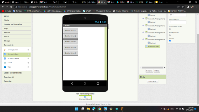
I wanted to control my HEXI_03 via a mobile app, so I opend MIT APP Inventor and start my application.
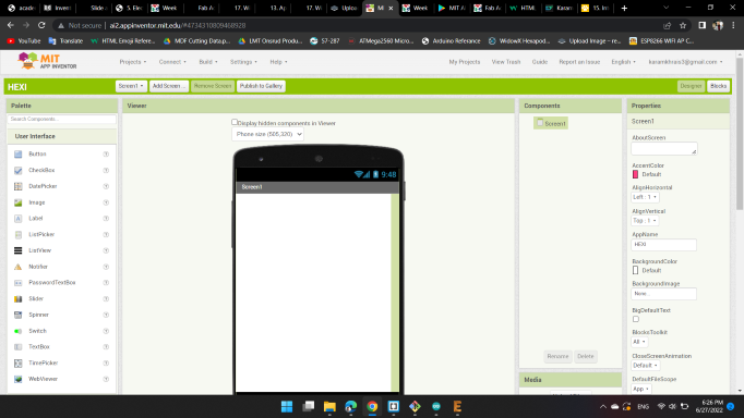
On the left, there are many palette, I started with "Layout" and choose "HorizontalArrangement" in order to organize my app.
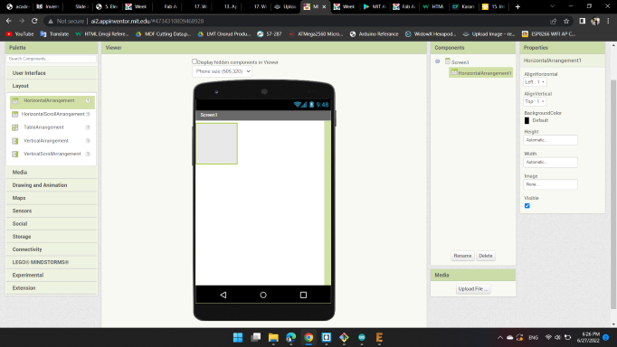
Next from "User Interface", I choose "Button".
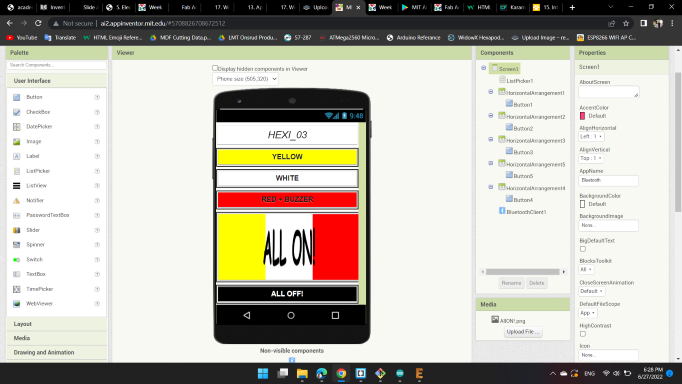
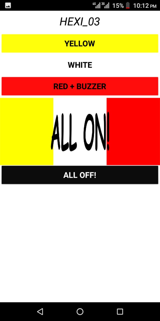
Because I had 3 LED rows on HEXI_03 and 2 options I wanted to added (All LED ON & ALL OFF); So, I had 5 buttons.
I also wanted to give the buttons some color to denote their functions, so the first button is yellow so I gave it a yellow color and wrote the name of the color in the middle.
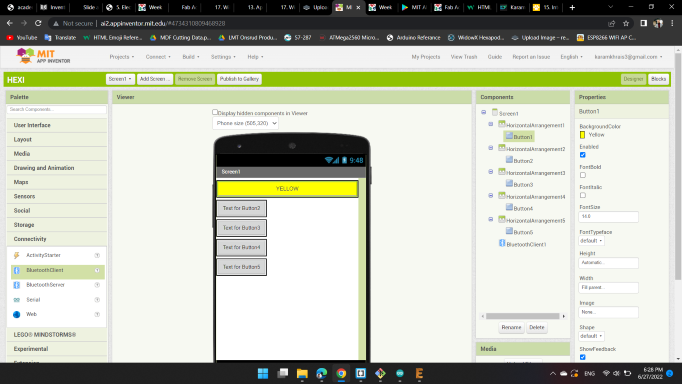
The rest buttons too.
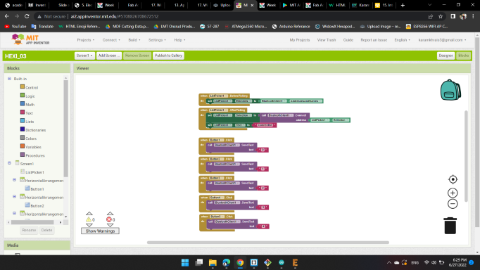
Then I moved to "Blocks" screen, which I add the code or in other meaning here I give life to the buttons on the screen.
For example; YELLOW button when it pressed, the mobile application will send (character or number or symbol) to the bluetooth module. So, here I programmed to send "0" to the bluetooth when I press on it.
Finally it's time to send the application to the mobile.
From Build > Android App (.apk).
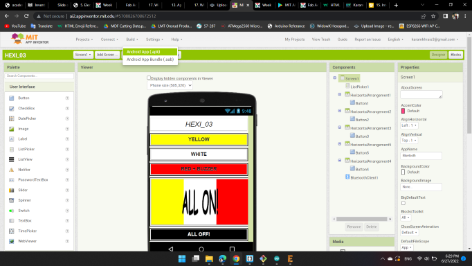
After few minutes, a QR Code appear in order to scanned.
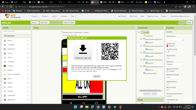
After scanned with the mobile, the application was ready.
With the same code I had used on HEXI_03, I'm used here.
                    #include <SoftwareSerial.h>

                    SoftwareSerial HEXISerial (1, 0); // RX (PA1), TX (PA0)

                    #define led1 5  //MISO (PA5) YELLOW
                    #define led2 4  //SCK (PA4) WHITE
                    #define led3 6  //MOSI (PA6) BUZZER/RED

                    char val;

                    void setup()
                    {
                      HEXISerial.begin(9600);

                      pinMode(led1, OUTPUT);
                      pinMode(led2, OUTPUT);
                      pinMode(led3, OUTPUT);
                    }

                    void loop()
                    {
                      if ( HEXISerial.available() )
                      {
                        val = HEXISerial.read();
                      }

                      if (val == '0')
                      {
                        HEXISerial.println("YELLOW LEDs ON!");

                        digitalWrite(led1, HIGH);
                        digitalWrite(led2, LOW);
                        digitalWrite(led3, LOW);
                      }

                      if (val == '1')
                      {
                        HEXISerial.println("WHITE LEDs ON!");

                        digitalWrite(led1, LOW);
                        digitalWrite(led2, HIGH);
                        digitalWrite(led3, LOW);
                      }

                      if (val == '2')
                      {
                        HEXISerial.println("RED LEDs & BUZZER ON!");

                        digitalWrite(led1, LOW);
                        digitalWrite(led2, LOW);
                        digitalWrite(led3, HIGH);
                      }

                      if (val == '4')
                      {
                        HEXISerial.println("ALL ON!");

                        digitalWrite(led1, HIGH);
                        digitalWrite(led2, HIGH);
                        digitalWrite(led3, HIGH);
                      }

                      if (val == '3')
                      {
                        HEXISerial.println("ALL OFF!");

                        digitalWrite(led1, LOW);
                        digitalWrite(led2, LOW);
                        digitalWrite(led3, LOW);
                      }
                    }
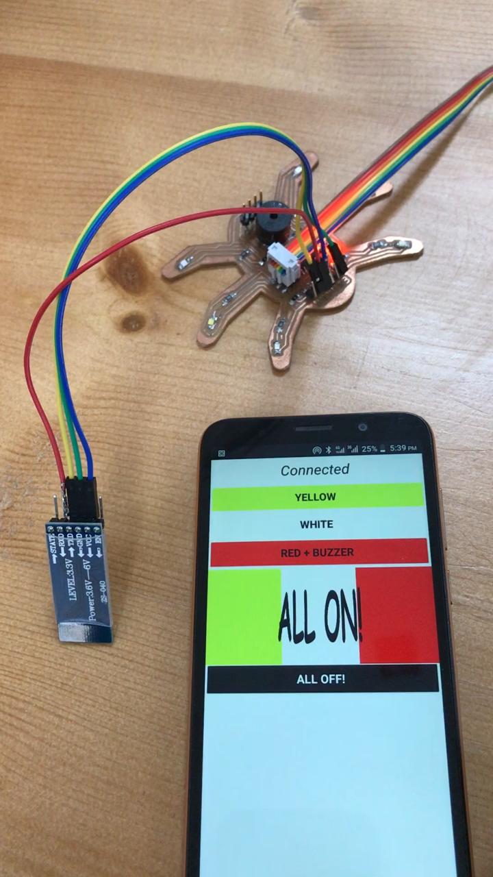
And here's the results 😁
You can download my files here: