This week we had to work with networking devices in order to communicate over a network. I decided to use Bluetooth as it's the simplest and most commonly used in the prototyping and comunicating with the world. Also, I wanted to used in my final project.
Learning:
- Group Assignment
-
Communication Protocols.
-
UART Interface
-
SPI Interface
-
I2C Interface
-
Communication Protocols.
- Individual Assignment
- HC-05 Bluetooth Module
- Connection
Group Assignments
Communication Protocols
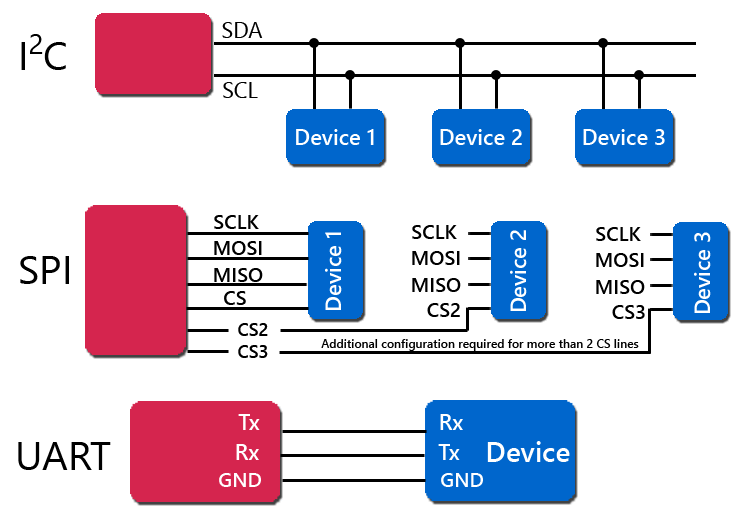
When we’re talking communication protocols, a UART, SPI and I2C are the common hardware interfaces people use in microcontroller development.
UART Interface
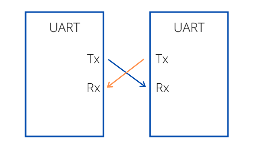
UART, or Universal Asynchronous Receiver/Transmitter, is a physical circuit in a microcontroller or single integrated circuit (IC) that is used to implement serial communication between devices in an embedded system. Essentially, a UART’s main purpose is to transmit and receive serial data.
In UART communication, two UARTs communicate directly with each other; the UART on the sender device, or the transmitting UART, receives parallel data from the CPU (microprocessor or microcontroller) and converts it to serial data. This serial data is transmitted to the UART on the receiver device, or the receiving UART. The receiving UART converts the received serial data back to parallel data and sends it to the CPU. In order for UART to convert serial-to-parallel and parallel-to-serial data, shift registers on the transmitting and receiving UART are used.
In UART communication, only two wires are required for communication: data flows from the Tx pin of the transmitting UART (Transmitter Tx) to the Rx pin of the receiving UART (Receiver Rx).
UART data is sent over the bus in the form of a packet. A packet consists of a start bit, data frame, a parity bit, and stop bits. The parity bit is used as an error check mechanism to help ensure data integrity.
UART is considered to be “universal” because the parameters including transfer speed and data speed are configurable by the developer. UART supports bidirectional data transmission, including half-duplex and full-duplex operations. It is also asynchronous, meaning it doesn’t use a clock signal to synchronize the output bits from the transmitting UART to the sampling bits on the receiving UART. Without a clock, the receiving and transmitting UART need to be on the same baud rate, or bit rate. This allows the system to know where and when the bits have been clocked.
SPI Interface
SPI, or Serial Peripheral Interface, is a serial communication protocol often used in embedded systems for high-speed data exchanges between devices on the bus. It operates using a master-slave paradigm that includes at least four signals: a Clock (SCLK), a Master Output/Slave Input (MOSI), a Master Input/Slave Output (MISO), and a Slave Select (SS) signal. The SCLK, MOSI, and MISO signals are shared by all devices on the bus. The SCLK signal is generated by the master device for synchronization, while the MOSI and MISO lines used for data exchange. Additionally, each slave device added to the bus has its own SS line. The master pulls low on a slave's SS line to select a device for communication.
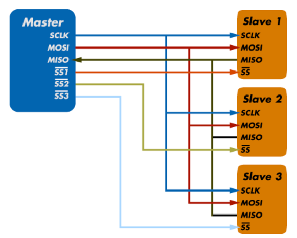
SPI communication supports Full-Duplex Communication , meaning that both the master and slave can transmit data simultaneously.
The exchange itself has no pre-defined protocol which makes SPI ideal for data-streaming applications. It also has no maximum speed; data speeds in excess of 100 MHz have been achieved.
I2C Interface
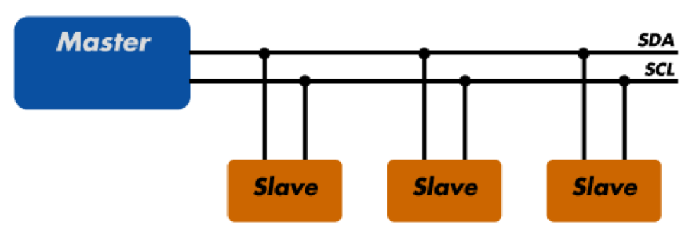
I2C, or Inter-Integrated Circuit, is a simple communication protocol often used in embedded systems as a way to transfer data between a master (or multiple masters) and a single slave (or multiple slaves) device. It is a bidirectional two-wire serial bus that uses serial clock (SCL) and serial data (SDA) wires to send and manage data bit by bit between devices connected to the bus.
In I2C operations, the master controls the exchange of data between the devices. A master device will signal to a slave in order to send data or request a response. To accomplish this, all slave devices must have a unique address that is included in the I2C message.
When sending data over the bus, each I2C message includes an address frame of the slave device and one or more data frames containing the data being transmitted. The message also includes start and stop conditions, read/write bits from either the master or slave, and ACK/NACK bits sent from the receiver for error checking.
I2C is considered to be synchronous, meaning it operates using a serial clock. The clock is driven by the master device which allows the output of bits to be synchronized to the sampling of bits by the clock signal shared between the master and the slave.
The standard data transfer rate of the I2C protocol is 100 kbps, although data speeds of up to 5 Mbps are possible with I2C devices configured in "fast mode" or "ultra-fast mode".
The receiving chip must be informed of the other chip’s transmission pace because no clock is transmitted. To correct for overshoot and ringing, a series resistor should be added to the UART line, just like with SPI. The signals are single-ended, which makes them more noise-sensitive, especially over long distances. Two additional signals, CTS (Clear to Send) and RTS (Request to Send), are sometimes added to the connection to improve its integrity.
We perform a group assignment where we use potentiometers to adjust led intensity. The led is connected to a slave controller board (Aybak board), and the potentiometer is attached to a master controller board (Amin board).
The potentiometer signal is wired to pin A0 on the master board, the led is wired to pin 5 on the slave board, and the final connections are TX on the master board to RX on the slave board and RX on the master board to TX on the slave board.
Individual Assignments
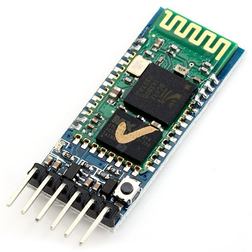
HC-05 Bluetooth Module
HC-05 Bluetooth Module is an easy to use Bluetooth SPP (Serial Port Protocol) module, designed for transparent wireless serial connection setup. Its communication is via serial communication which makes an easy way to interface with controller or PC.
Connection
I connected the Bluetooth wires in FTDI Pin Headers
- VCC > VCC
- GND > GND
- TX > RX
- RX > TX
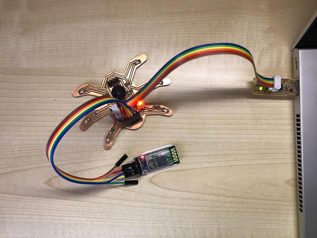
After connect the bluetooth module with the HEXI_03 PCB and the ISP AVR Programmer with the laptop, it's time to connect the bluetooth module with the mobile app.
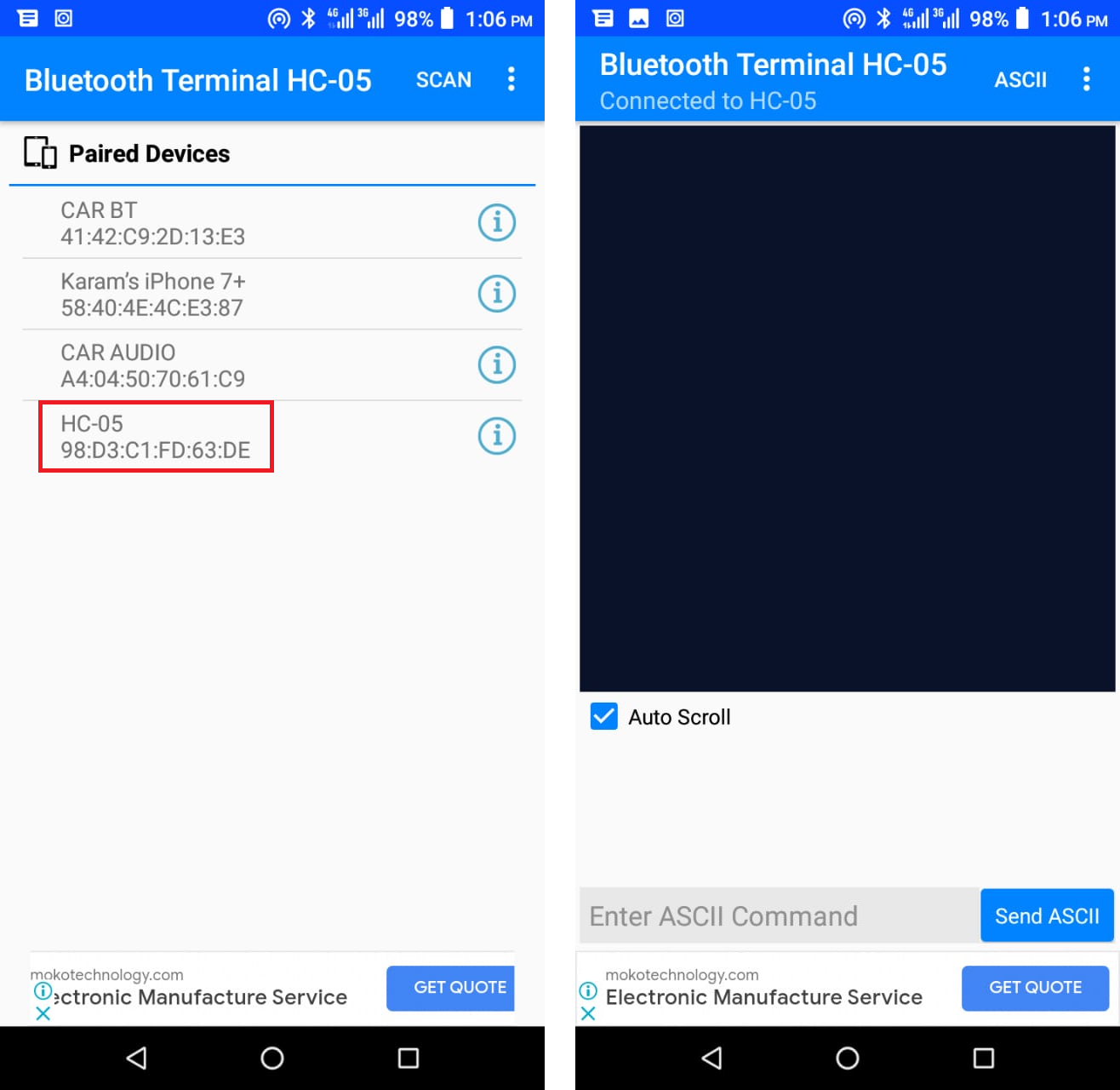
I downloaded ![]() Bluetooth Terminal HC-05 and used it to send an recieve data.
Bluetooth Terminal HC-05 and used it to send an recieve data.
I Arduino IDE, to run the Serial Communication, I used <SoftwareSerial.h> library
The code is to control the HEXI_03 PCB via HC-05 Bluetooth Module instead of Ultrasonic Sensor from the previous week as input.
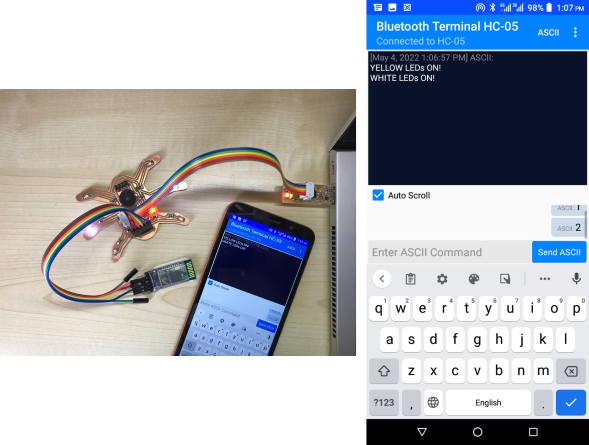
1st order is to turn Yellow LED's ON.
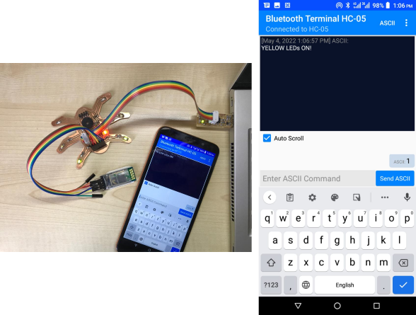
2nd order is to turn White LED's ON.
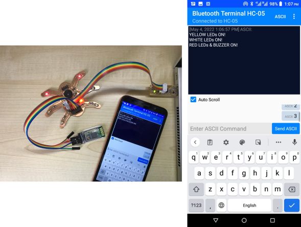
3rd order is to turn Red LEDs & Buzzer ON.
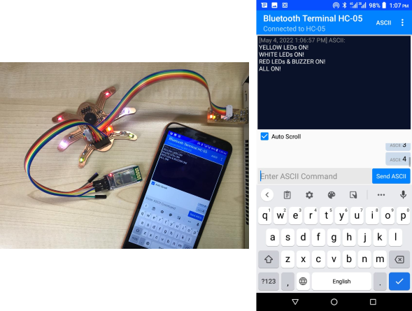
4th order is to turn All ON.
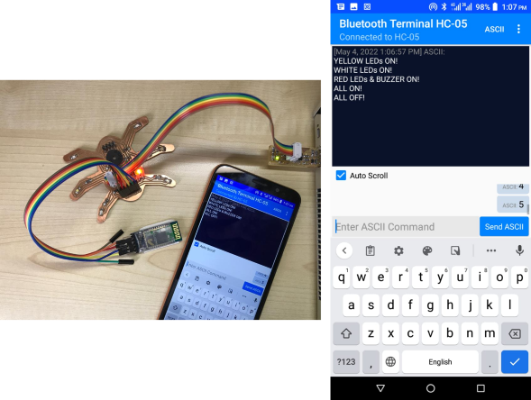
4th order is to turn All OFF.
The code I used is below 👇
                        #include <SoftwareSerial.h>

                        SoftwareSerial HEXISerial (1, 0); // RX (PA1), TX (PA0)

                        #define led1 5  //MISO (PA5) YELLOW
                        #define led2 4  //SCK (PA4) WHITE
                        #define led3 6  //MOSI (PA6) BUZZER/RED

                        char val;

                        void setup()
                        {
                          HEXISerial.begin(9600);

                          pinMode(led1, OUTPUT);
                          pinMode(led2, OUTPUT);
                          pinMode(led3, OUTPUT);
                        }

                        void loop()
                        {
                          if ( HEXISerial.available() )
                          {
                            val = HEXISerial.read();
                          }

                          if (val == '1')
                          {
                            HEXISerial.println("YELLOW LEDs ON!");

                            digitalWrite(led1, HIGH);
                            digitalWrite(led2, LOW);
                            digitalWrite(led3, LOW);
                          }

                          if (val == '2')
                          {
                            HEXISerial.println("WHITE LEDs ON!");

                            digitalWrite(led1, LOW);
                            digitalWrite(led2, HIGH);
                            digitalWrite(led3, LOW);
                          }

                          if (val == '3')
                          {
                            HEXISerial.println("RED LEDs & BUZZER ON!");

                            digitalWrite(led1, LOW);
                            digitalWrite(led2, LOW);
                            digitalWrite(led3, HIGH);
                          }

                           if (val == '4')
                          {
                            HEXISerial.println("ALL ON!");

                            digitalWrite(led1, HIGH);
                            digitalWrite(led2, HIGH);
                            digitalWrite(led3, HIGH);
                          }

                          if (val == '5')
                          {
                            HEXISerial.println("ALL OFF!");

                            digitalWrite(led1, LOW);
                            digitalWrite(led2, LOW);
                            digitalWrite(led3, LOW);
                          }
                        }
You can download my files here: