This week focuses on input devices. Input devices are used to sense the environment around us, you can sense and track different parameters using sensors and have them create a certain action based on that input.
Learning:
- Group Assignment
- Testing Analog Levels and Digital Signals
- Individual Assignment
- Ultrasonic Sensor
- PCB Schematic
- PCB Layout
- Mods CAM
- Soldring
- Programming
Group Assignments
Testing Analog Levels and Digital Signals
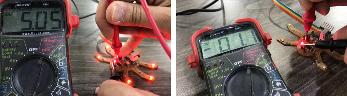
In this part we measured the level of a Push Button in its two states, Normal and Pressed. The push button (normally open) is connected to Vcc through 10kOhm resistor, so in its normal state the level will be 5 V (digitally high). When pressed the level will be 0 V (digitally low).
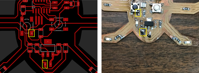
Using the Digital Multimeter, in the normal state the measured value is 5.05 V (digitally 1 or high), and when pressed, the measured value is -1.1 mV (digitally 0 or low).
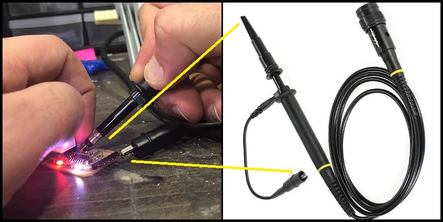
We used Oscilloscope to measure the same input signal. To connect the oscilloscope probe, connect the spring loaded end (hock or clamp) to GND and the pin head to test point, which is the push button signal.
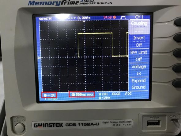
Note that voltage scale is 2 V/division and time scale is 500 ms/division.
In the normal state, the signal height is 2.5 vertical divisions, which equals to 5V (2.5 divisions x 2 V/division). When the button is pressed, the level drop to fit over the zero line. The button had been pressed for 2 seconds (4 horizontal divisions x 500 ms/division).
Individual Assignments
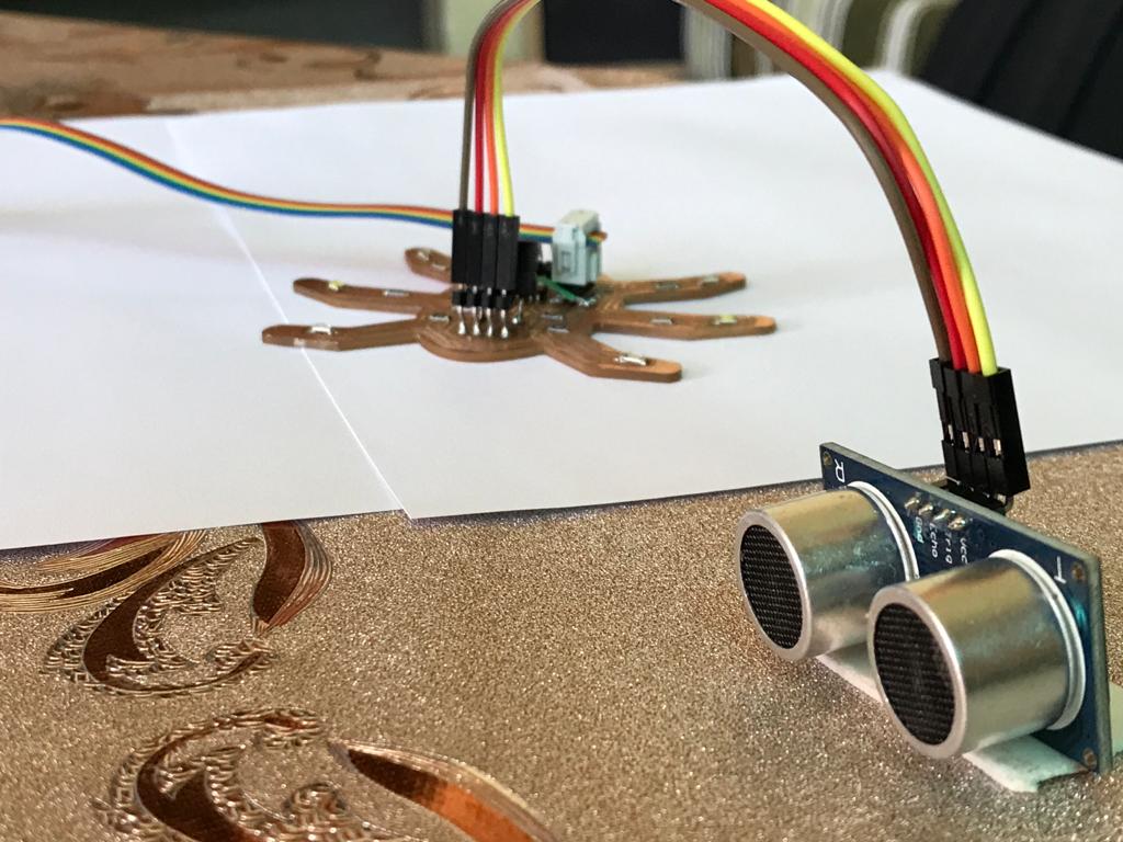
Ultrasonic Sensor
In this assignment, I want to design a board similar to the board for the final project, Ultrasonic Sensor will be the major input devices in my PCB + Buzzer and some LED's.
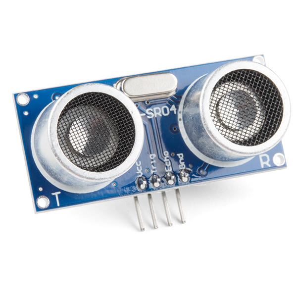
An Ultrasonic Sensor is an instrument that measures the distance to an object using ultrasonic sound waves. An ultrasonic sensor uses a transducer to send and receive ultrasonic pulses that relay back information about an object's proximity.
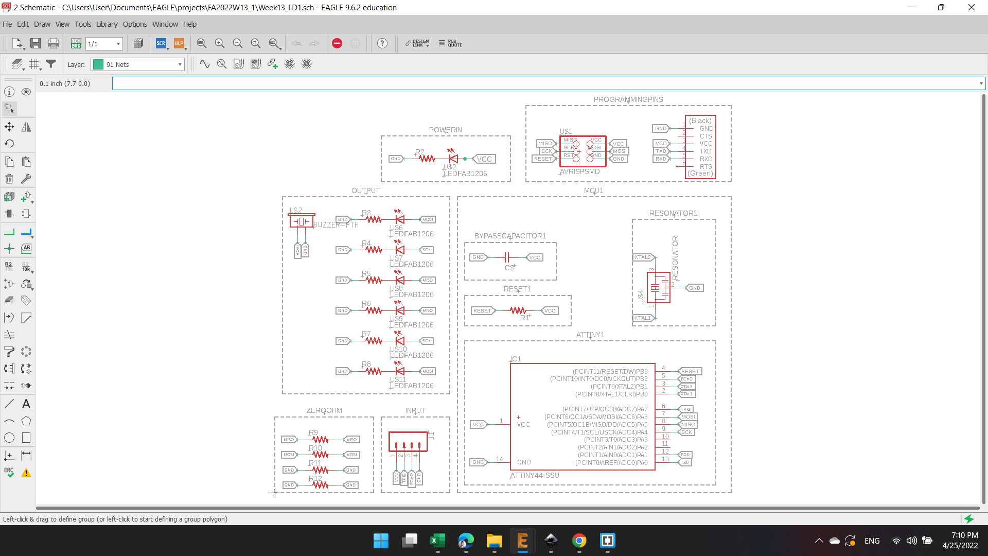
PCB Schematic
The schematics of this PCB is almost the same for the previous PCB at week 6 and week 10, with a difference in the inputs to be 4 pin headers for the Ultrasonic Sensor and 6 LED's + 1 Buzzer as output. I removed the power inputs (Voltage Regulator).
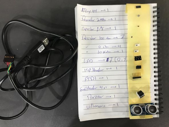
- ATtiny44"ATTINY44-SSU SOIC14"
- Capacitors"CAP-UNPOLARIZEDFAB"
- Resistors"RES-US1206FAB"
- ISP AVR Male Header 2x3 SMD"AVRISPSMD"
- FTDI Male Header 6x1"FTDI-SMD-HEADER"
- Male Pin Headers"Conn_04"
- LEDs"LEDFAB1206"
- Buzzer"Buzzer-PTH"
- RESONATOR"Resonator"
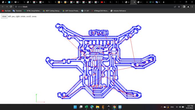
PCB Layout
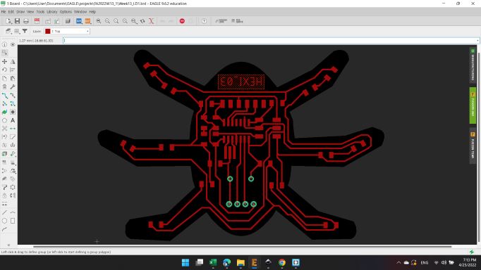
For the board layout, I distributed the components as before, with addition of buzzer pin headers and the 4 pin headers for the ultrasonic sensor.
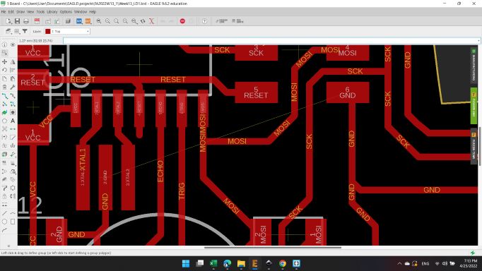
I connected each LED's row leg together. The last two legs with MISO pin, and the middle legs with SCK pin, and the front two legs and buzzer with MOSI pin.
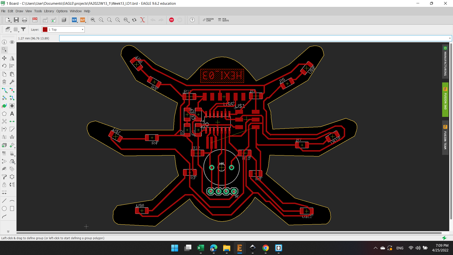
I have only one wire "GND" unconnected, so I decided to extend an external wire after finishing the board production.
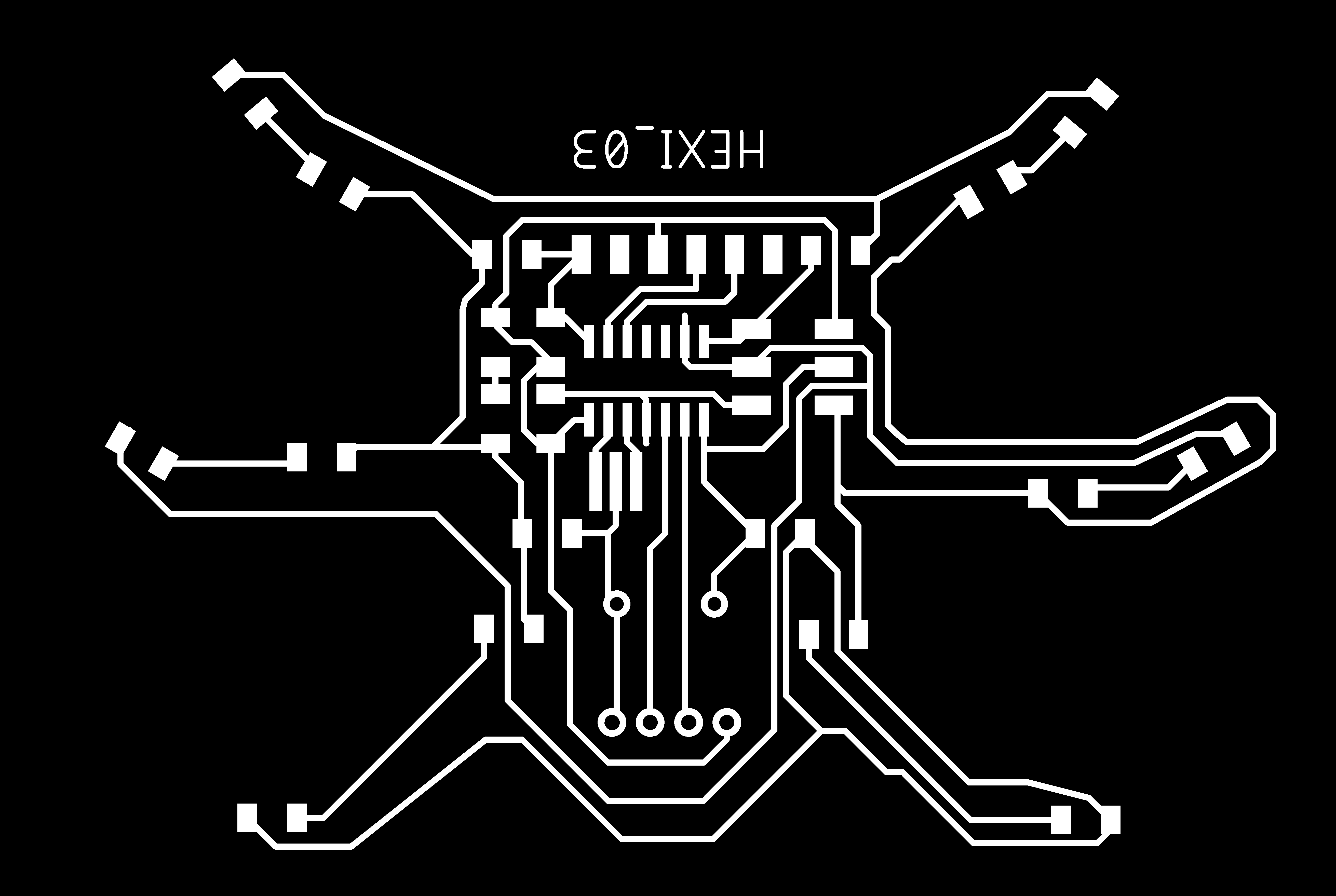
Here's the board ready to be exported.
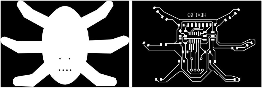
So, I turned off all layers and kept the Top and Pads, and exported as image.
The second image with Dimension and Pads layers.
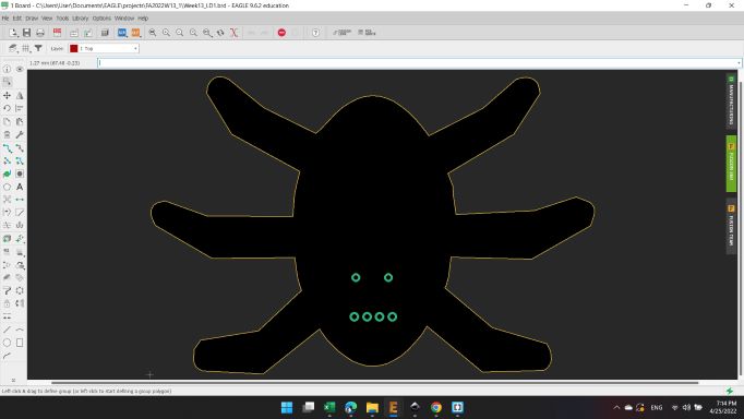
For the Outline image, I painted the inner area with white color and kept the pads holes in black in order to drill it.
Mods CAM
After the two images are ready, I opened Mods and import the first image Trace, with the same previously options.
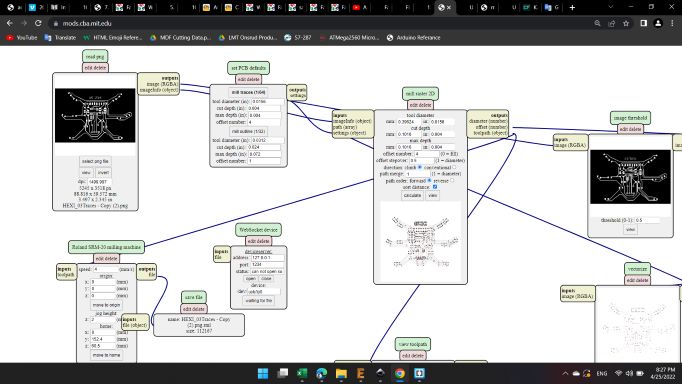
Here's the traces toolpath.
And for the second image, also the same previously options.
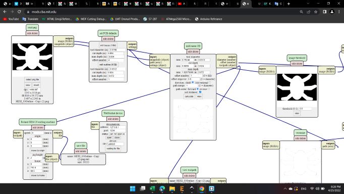
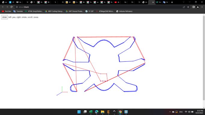
And here's the outline toolpath.
Soldring
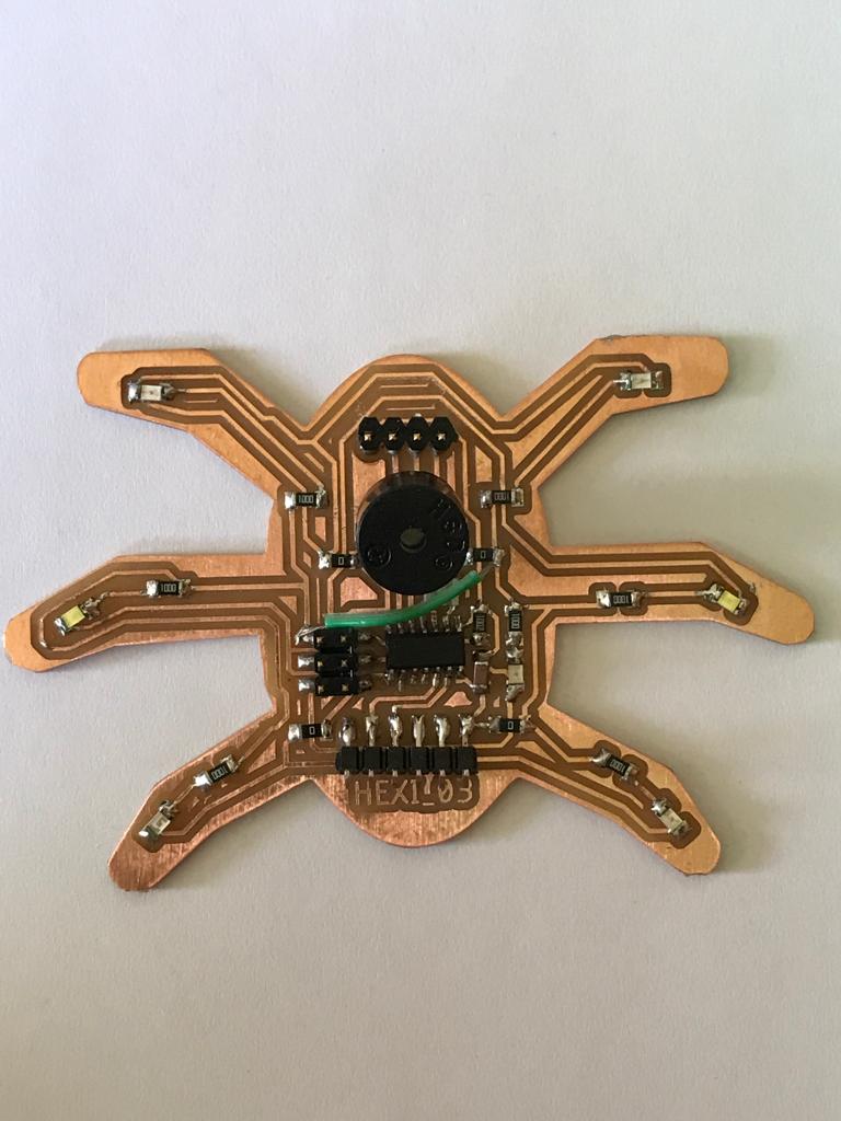
After about an hour, the machine finished making the two images.
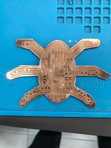
Here's the components to be soldering.
And here's the PCB ready to programming 😁
Programming
Final stage is to write the code.
The code I used is below 👇
                        int led1 = 5;  //MISO YELLOW
                        int led2 = 4;  //SCK WHITE
                        int led3 = 6;  //MOSI BUZZER/RED

                        void setup()
                        {
                          pinMode(led1, OUTPUT);
                          pinMode(led2, OUTPUT);
                          pinMode(led3, OUTPUT);
                        }

                        void loop()
                        {
                          digitalWrite(led1, HIGH);
                          delay(1000);
                          digitalWrite(led1, LOW);
                          delay(1000);
                          digitalWrite(led2, HIGH);
                          delay(1000);
                          digitalWrite(led2, LOW);
                          delay(1000);
                          digitalWrite(led3, HIGH);
                          delay(1000);
                          digitalWrite(led3, LOW);
                          delay(1000);
                        }
The second code with the input "Ultrasonic Sensor":
The code I used is below 👇
                        int Yellow = 5;  // PA5 MISO YELLOW
                        int WHITE = 4;  // PA4 SCK  WHITE
                        int RED = 6;  // PA6 MOSI BUZZER/RED

                        int trig = 7; // PA7 > 6 Trig
                        int echo = 8; // PB2 > 5 Echo

                        long duration, distance;

                        int cm = 0;

                        void setup()
                        {
                          Serial.begin(9600);
                          Serial.println("Serial Started...");

                          pinMode(echo, INPUT);
                          pinMode(trig, OUTPUT);

                          pinMode(Yellow, OUTPUT);
                          pinMode(WHITE, OUTPUT);
                          pinMode(RED, OUTPUT);
                        }

                        void loop()
                        {
                          digitalWrite(trig, LOW);
                          digitalWrite(trig, HIGH);
                          digitalWrite(trig, LOW);

                          int duration = pulseIn (echo, HIGH);
                          cm = duration*0.034/2;

                          Serial.println(cm);

                          if (cm >= 30)
                          {
                            digitalWrite(Yellow, LOW);
                            digitalWrite(WHITE, LOW);
                            digitalWrite(RED, LOW);
                            delay(1000);
                            digitalWrite(Yellow, HIGH);
                            digitalWrite(WHITE, LOW);
                            digitalWrite(RED, LOW);
                            delay(1000);
                          }

                           else if (cm < 30 && cm > 15)
                           {
                            digitalWrite(Yellow, LOW);
                            digitalWrite(WHITE, LOW);
                            digitalWrite(RED, LOW);
                            delay(500);
                            digitalWrite(Yellow, LOW);
                            digitalWrite(WHITE, HIGH);
                            digitalWrite(RED, LOW);
                            delay(500);
                          }

                           else if (cm < 15 && cm > 5)
                           {
                            digitalWrite(Yellow, LOW);
                            digitalWrite(WHITE, LOW);
                            digitalWrite(RED, LOW);
                            delay(250);
                            digitalWrite(Yellow, LOW);
                            digitalWrite(WHITE, LOW);
                            digitalWrite(RED, HIGH);
                            delay(250);
                          }

                          else if (cm <= 5)
                           {
                            digitalWrite(Yellow, LOW);
                            digitalWrite(WHITE, LOW);
                            digitalWrite(RED, HIGH);
                            delay(100);
                          }
                        }
You can download my files here: