9. Output Devices
o. Evaluation suggestions
Local
Individual assignment: typo in Design & Fabrication section: “esp32 xiaO32c3”. Do you mean Xiao esp32c3? source code link for esp32 is for an LED matrix & not the servo motor example shown in your video source code link for ATtiny1614 not related to the led example shown in your video
thanks Instructor Steven for pointing out my lacking of knowledge in the placeholders. Went internet search then realise in electronics sector, they label items as [Brand/Model Name in this case it means small in chinese] [Microcontroller Type/Family in this case it is Esp32][Model in this case is C3] so I should have written it as Xiao ESP32c3. So xiao is the brandname. I will not like to not edit the wordings below so that I can always remember this error which i see it in this section. Thanks for the learning opportunity! I already read the data sheet so know about the terms, but i just couldn't make the order stick in my head.
When doing Fabacademy projects, I sometimes will open multiple versions of my git repo in my double screen desktop. I was shocked to see the pictures correct but my code was wrong. Then I realised that i saved them to the wrong folders. I also wanted to make most of the items myself from scratch after learning so did not use the markdown template. After all this documentation error, then I realise better the value of proper planning and how to plan and appreciate good documentation. Hope this will prevent others from making same mistake as me -- Stubbornly want to learn but clumsy and mentally slow at times.
Group Assignment
G1. Group Assignment- Output Devices
- Measure the power consumption of an output device
Attached is the link to group assignment
Individual Assignment
- ☑ Linked to the group assignment page
- ☑ Documented how you determined power consumption of an output device with your group
- ☑ Documented what you learned form interfacing output device(s) to microcontroller and controlling the device(s)
- ☑ Documented your design and fabrication process or linked to the board you made in a previous assignment
- ☑ Explained the programming process/es you used
- ☑ Explained any problems you encountered and how you fixed them
- ☑ Included original design files and source code
- ☑ Included a 'hero shot' of your board
Power Consumption Determination
In collaboration with my group, I determined the power consumption of our output device by measuring the voltage across it and the current flowing through it using a multimeter. We then calculated the power using the formula P = V x I.
Interfacing Output Devices
From interfacing the output devices to the microcontroller, I learned the importance of understanding the electrical characteristics of both the microcontroller pins and the devices. This ensured that we provided the correct voltage and current levels, avoiding damage to both the controller and the output device.
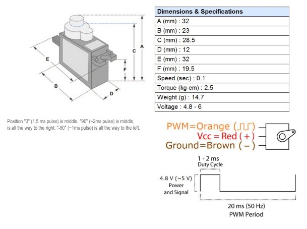
Link to sg90 datasheet, key info shown in image below
| Purpose | Specification | Importance | Unit |
|---|---|---|---|
| 3D Design | Dimensions (A, B, C, D, E, F) | I will use this to design the physical space and mountings in the 3D model where the servo will be placed. | mm |
| Weight | This is useful if i want to estimate the mass. | g | |
| Programming | Speed | Crucial for programming the response time and movement sequences of the servo. | sec/60° |
| Torque | Informs me the servo's ability to handle the required load without stalling. | kg-cm | |
| Electronics | Voltage Range | I used wrong voltage too many times in the past damaging the device. So future me, please use correct range. | V |
| PWM Signal Details | I am still learning to use this to control the servo's position accurately. | 1-2 ms Duty Cycle 20 ms PWM Period |
|
| Wire Color Coding | I use this to connecting to power (Vcc), ground, and control (PWM). | - |
Design and Fabrication Process
My design process started with a schematic in F360. After laying out the board, I fabricated it using a PCB mill, followed by soldering the components and the esp32 xiaO32c3correction xiao esp32c3. For more on the board I made in a previous assignment, visit this link.
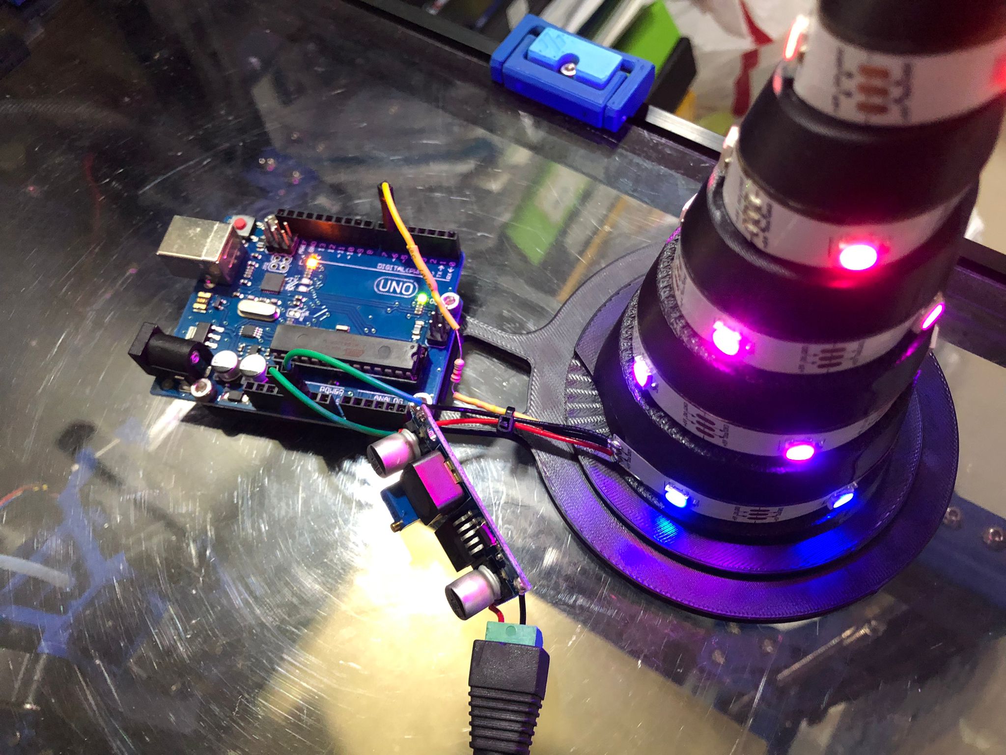
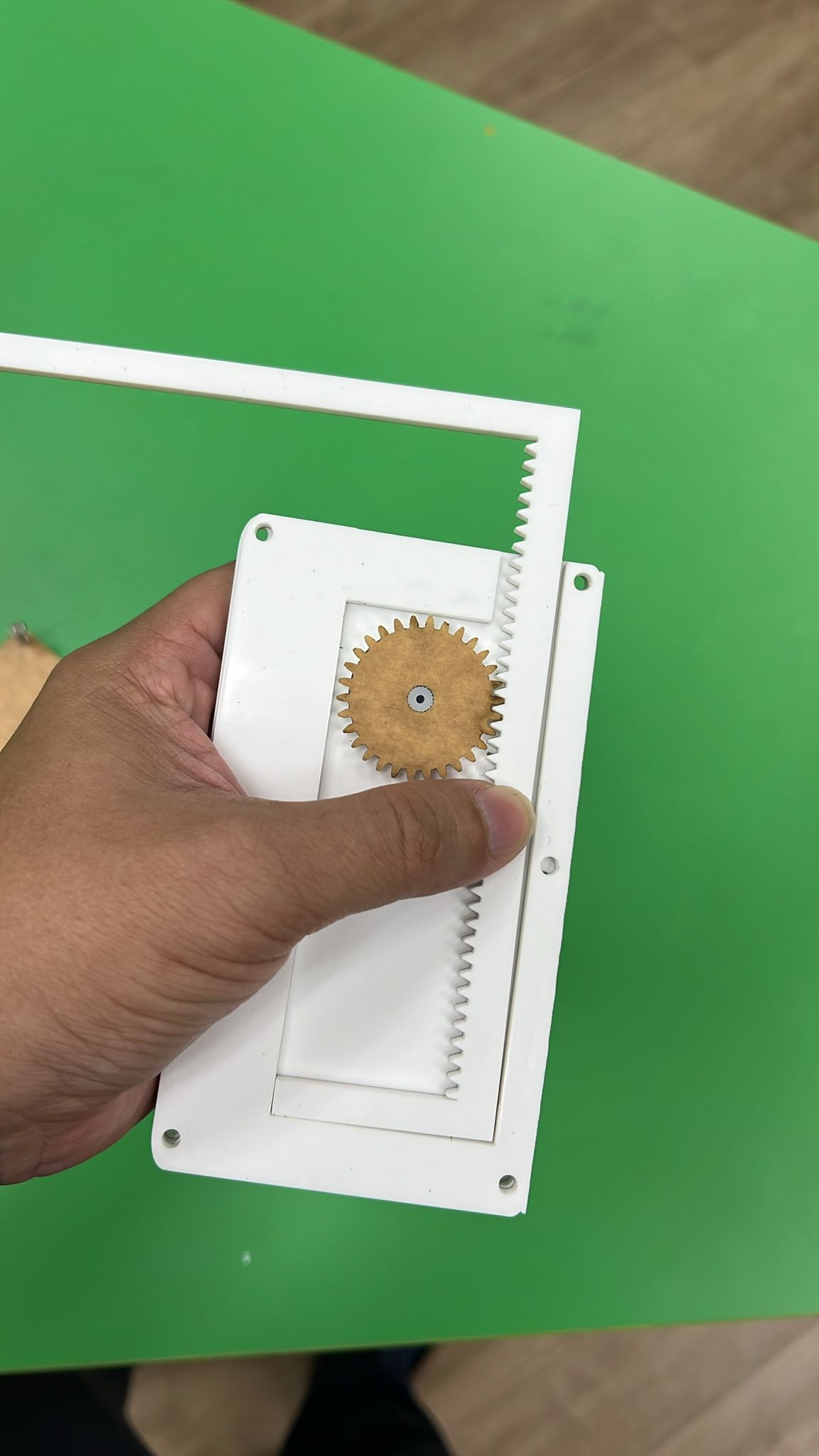
I wanted the servo to release balls in my final project. So i am trying out the rack and pinion in this video.
I at first had issues with my coding shown below.
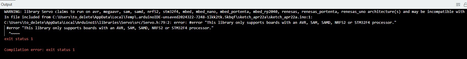
Shortly, (Actually took awhile as i tried many search on troubleshooting), I found that ESP 32 have differemt timers from Arduino so library specific to ESP32 should be used.
I upload the code successfully and watch the servo turn in video below.
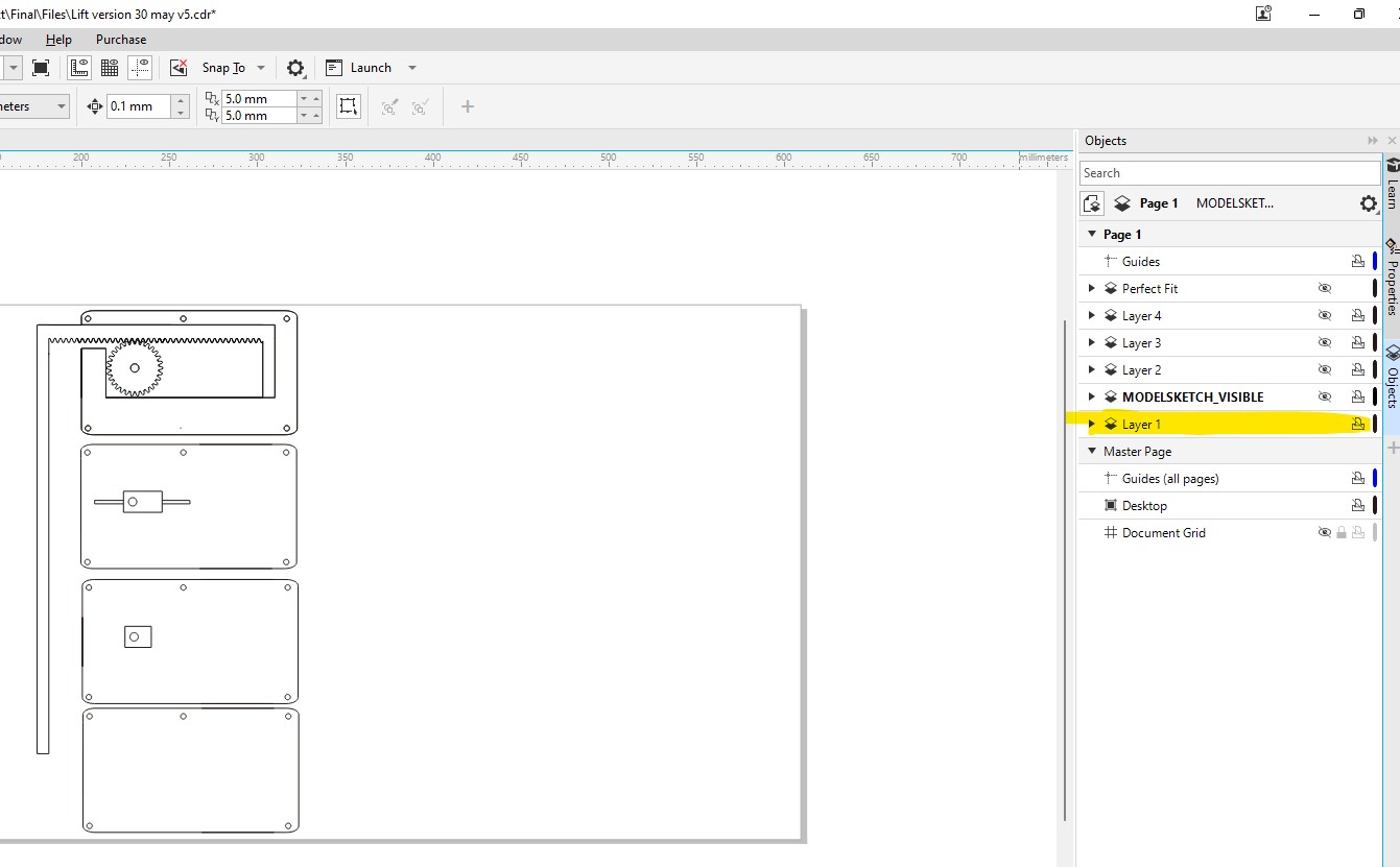
Next I draw some rack and and pinion, refer to layer 1 of my design file for the updated rack and pinion file to attach to my servo to convert rotational motion into translation mode. I hope to use the mechanism to help to release my balls from the slide. But this is only the first draft.
Programming Process
I used the Arduino IDE for programming the microcontroller. This involved writing the code, compiling it, and uploading it to the microcontroller using a USB connection. I programmed esp32 to control the servo.
Source Code
The following is the source code used for controlling the servo motor in our project. It utilizes the ESP32Servo library and is written in C++ for the Arduino programming environment:
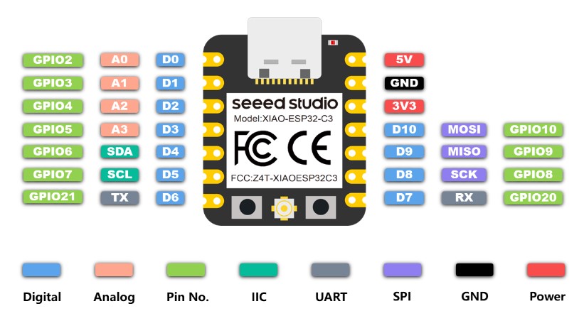
My ESP32 Pin 20 is connected to Servo, Pin 5v connect to 5v, Gnd to Gnd.
        #include <ESP32Servo.h>

        Servo myservo;  // create servo object to control a servo
        int pos = 0;    // variable to store the servo position

        void setup() {
          myservo.setPeriodHertz(50);    // standard 50 hz servo
          myservo.attach(20, 500, 2400);  // attaches the servo on GPI20 to the servo object
                                          // and sets min and max microseconds (the 544 and 2400 are defaults for 0 and 180 degrees)
        }

        void loop() {
          // Sweep the servo from 0 to 180 degrees
          for (pos = 0; pos <= 180; pos += 1) {
            myservo.write(pos);              // tell servo to go to position in variable 'pos'
            delay(15);                       // waits 15ms for the servo to reach the position
          }
          // Sweep the servo from 180 back to 0 degrees
          for (pos = 180; pos >= 0; pos -= 1) {
            myservo.write(pos);              // tell servo to go to position in variable 'pos'
            delay(15);                       // waits 15ms for the servo to reach the position
          }
        }
Problems Encountered
I encountered a challenge when I first attempted to upload the program to the microcontroller, receiving a 'no serial data received' error. After some research and troubleshooting, I found that pressing the boot button during the upload process resolved the issue.
Next I encouteered challenge when I tried to use the servo.h library but Esp32 did not work with the library. hence i needed to get esp32servo library which works with my servo.
I actually also done coding and documentation of my designed in easypcb ATTINy1614 for inbuilt led & rotary encode in the past, but i removed it as during that time, I only did not make my own programmer but use Arduino as programmer so had to redo but shown below is my work.
You may refer to Attiny1614 code rotary for the code. For the old pictures have to revert at git history and honestly, i tried to do that before, It was very tough as I did not think i will need to go back to history in the past.
.
Design Files and Source Code
Below are the original design files and source code for my project.
- Design Files
- Source Code for ESP32
- Source Code Zip for ATTINY1614
Project 'Hero Shot'
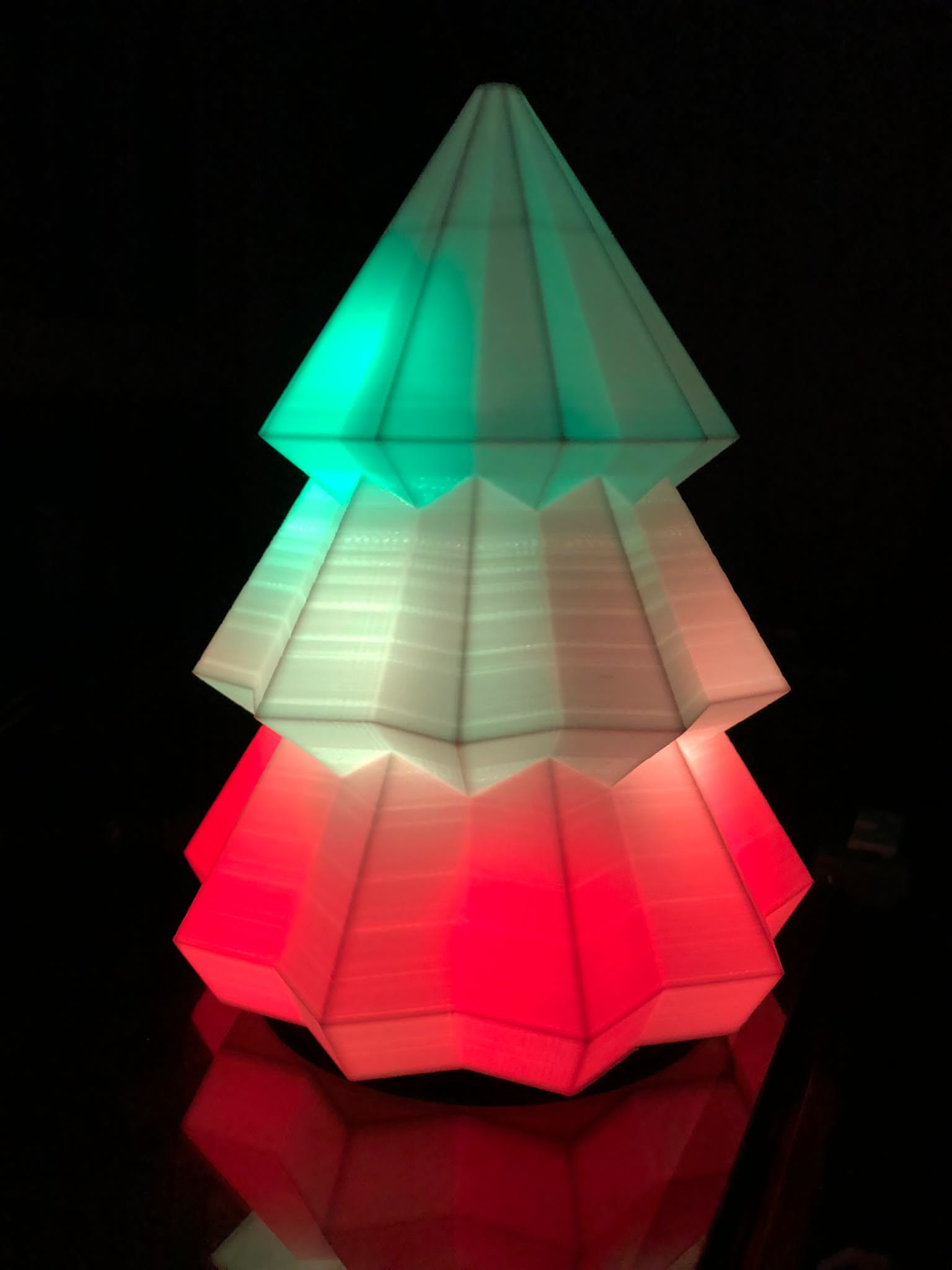
Here is the 'hero shot' of my board. Actually, I dont like to have any hero shots, I am a teacher, I just like my students and young ones behind me to shine.
but if have to put something here, I place this working video.Personally My hero shot is this event in 2023, where I helped my students to go volunteer at community to teach how to programme led strips and 3d printing. Honestly, they can do it without me but happy to played a small role in nuturing their growth to use DF to empower community.