5. 3D Scanning and Printing
Reflection
Used a lot of 3D printers, Currently as of May 2024, I love Bambu x1 the best! There is no elephant foot problem!!! The slicer is also great! Love it.
Group Assignment
Attached is the link to group assignment
Individual Assignment
0. Instructors Suggestions
To fix:
Please add the advantages and disadvantages of 3D printing. you can use your Taekwondo chain to talk about why this is possible with 3D printing and not, let’s say, with laser cutting.
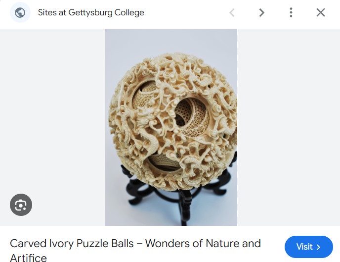
- If I would like to do the keychain(with rotating parts) with laser cutting or another substractive methods, I do not have the experts skills to make multiple axis milling, like ones involved in the ivory ball below that is considered a marvel mastery of substractive craftsmanship. I added a table of comparison of it's advantage and disadvantages compared to substractive:.
| Feature | 3D Printing | Subtractive Methods (e.g., Laser Cutting) |
|---|---|---|
| Material Usage | Material is added layer by layer, hence less waste. | Material is removed from a material -> more waste. |
| Complexity of Shapes | Capable of creating highly complex and intricate shapes that may be difficult with subtractive methods. | Limited to skills of craftsman at cutting & carving. |
| Production Speed | Slower for detailed parts. | Faster for simple makes. |
To fix:
- Reflection at top is empty --- 6 May inserted reflection
- add screencap of intermediate stage of design, explain why this design is difficult to manufacture subtractively, --- 6 May: Discussed with instructor, reordered flow of write up. Print in one piece with moving parts is not easy done substractively
- "example of use" pic doesn't show how it is used --- 6 May: It is the taekwondo items which the students use to train with. Fixed the video.
- video is 0 sec --- 6 May:Fixed the video. - upload & link to scanned image --- 6 May: Uploaded the glb file.
- your onshape pip part not linked to the printed part --- 6 May: The onshape part was a demonstration of how to do the ball joint using onshape. Tinkercad is sufficient to do the ball joint using unions option.
- "Useful Theory" & "Issues and Rectificatin" are empty - either fill in or remove. --- 6 May: Removed as they are theory
Checklist
- ☑ Linked to the group assignment page -- Done
- ☑ Explained what you learned from testing the 3D printers -- Know the limits of your printer and plan in the design process
- ☑ Documented how you designed and 3D printed your object and explained why it could not be easily made subtractively -- Single Object connected by Ball Joints can not be made by easily by subtractive manufacturing
- ☑ Documented how you scanned an object --Done Polycam
- ☑ Included your original design files for 3D printing -- done
- ☑ Included your hero shots -- included pictures of work
I3. Workflow for Using Onshape to make the print in place inner part
I did this section after my instructor looked through the tinkercad and commented that Tinkercad is too easy hence i should do onmshape too. Below is how i did the ball joint in onshape hence the title is I3.
| Step | Description |
|---|---|
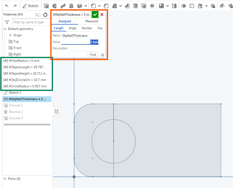
1. Sketch
|
I drawn a rectangle, I fillet two edges, I drawn a circle and a line to act as revolving axis. I placed the design which I am replicating from Tinkercad picture shown. |
2. Extrude.
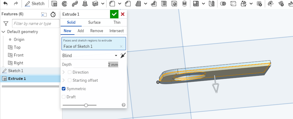
|
I selected the extrude function on the rectangle and selected the desired parameters. |
3. Revolve
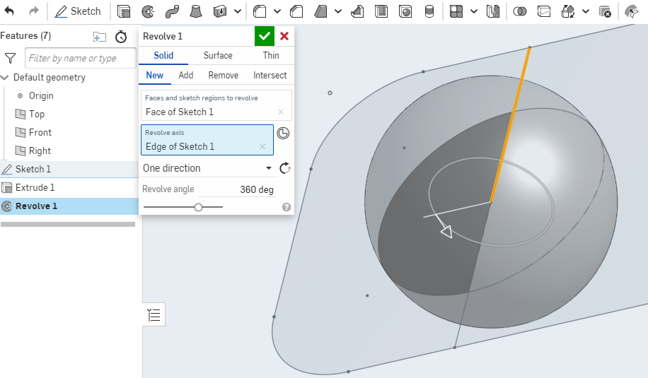
|
I sselected the circle and used revolve 360 about the chosen axis. |
4. Export
|
I parameterised the dimensions and selected the objects to export. |
I1. Enhanced Workflow: Tinkercad Design to 3D Printing with Ultimaker 3
i tried to detail the process of designing in Tinkercad, exporting the design, slicing with Cura for Ultimaker 3.
| Step | Activity | Details and Adjusting Cura Settings |
|---|---|---|
1. Tinkercad Design 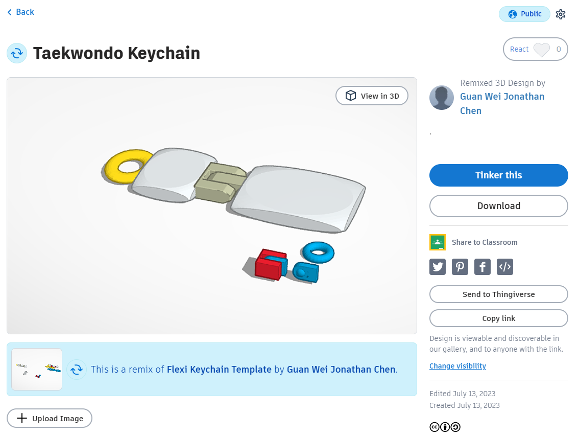
|
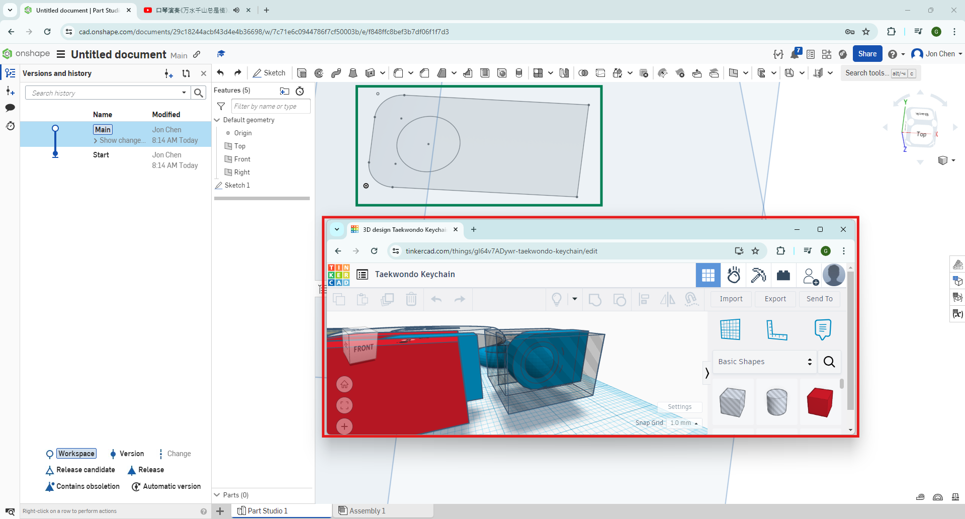
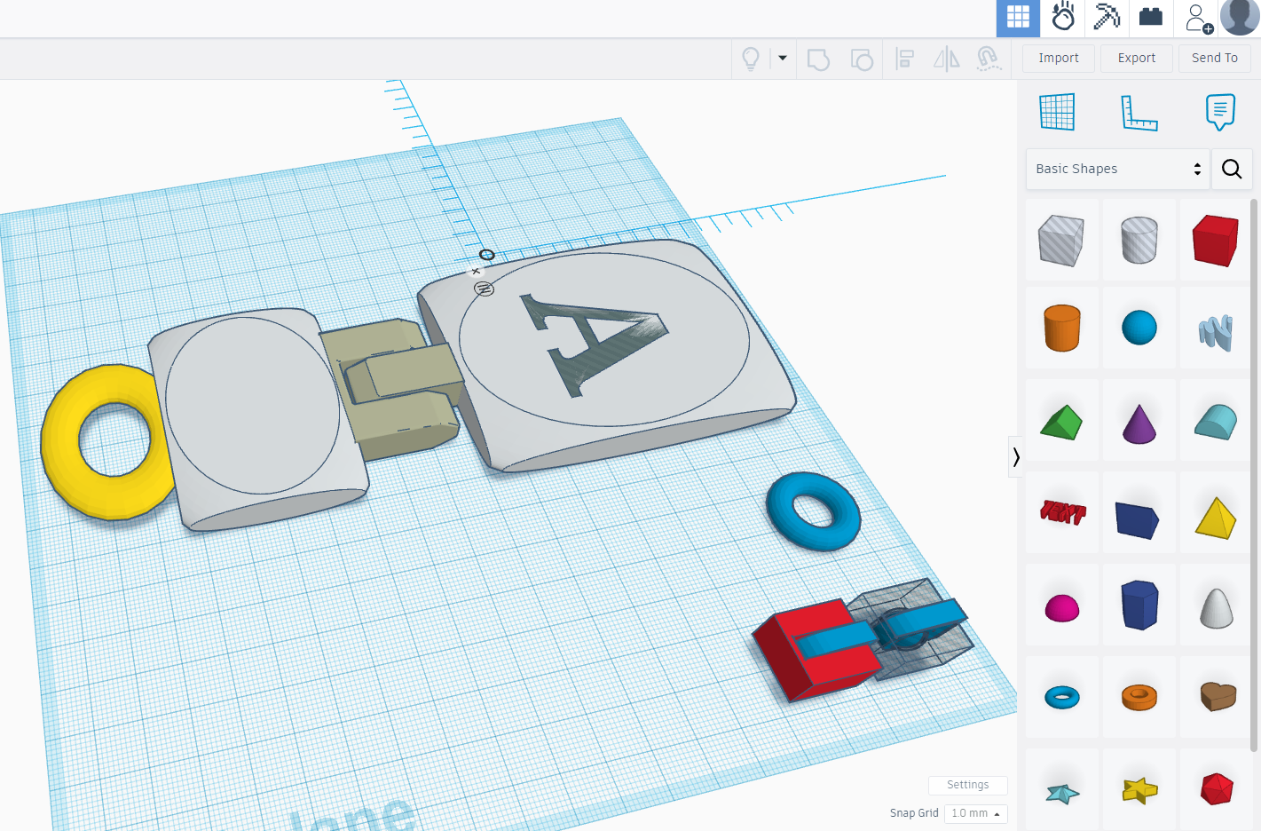
Create your 3D model | I Used Tinkercad to design my model, I considered printability and the final application. I used drag and drop to place in the 3D objects and merge them together to form the shapes.
Picture shows the 3D Design made in Tinkercad. The Link to the file is here. |
2. Exporting Model
|
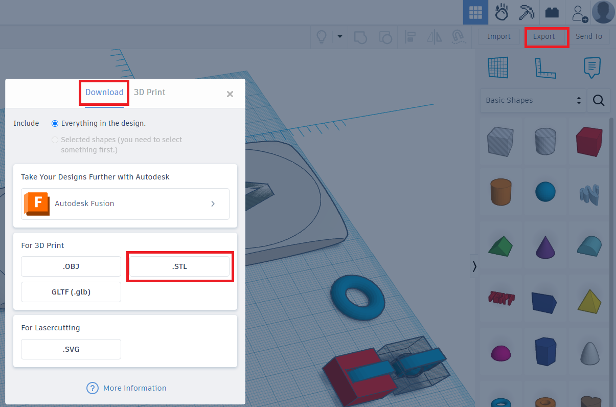
Export as STL file | I Exported my Tinkercad design as an STL file, ready for slicing in Cura. |
3. Preparing in Cura
|
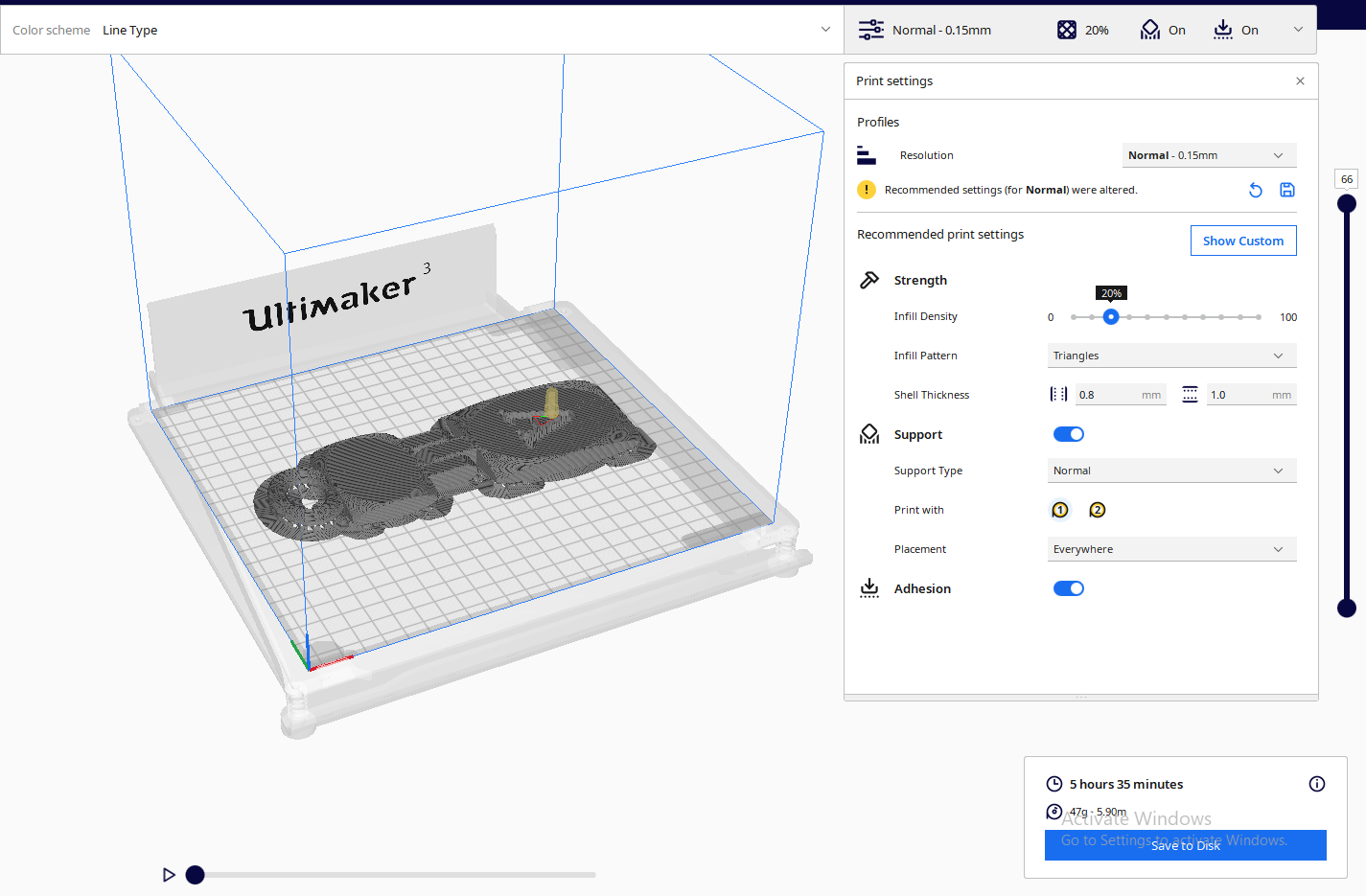
Load STL file in Cura | I Choose Ultimaker 3 as my printer in Cura and imported the STL file. Cura applies default settings optimized for Ultimaker 3. |
4. Cura Default Settings and Adjustments
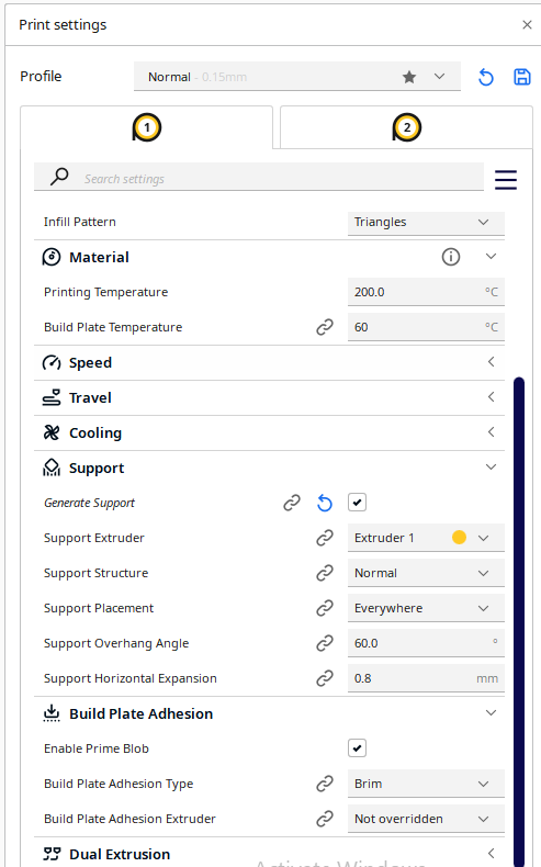
|
Optimize settings for 3D Printing |
Layer Height: Default is 0.16mm. Increase layer height (e.g., to 0.2mm) for faster prints with slightly reduced detail, or decrease (e.g., to 0.1mm) for higher detail in cosmetic parts. Infill: Default is 20%. Increase for parts requiring higher strength, decrease for less critical parts to save material and time. Print Speed: Default is 50 mm/s. Increase speed (e.g., to 70 mm/s) for less detailed parts to shorten print time, or decrease (e.g., to 40 mm/s) for intricate designs to enhance quality. Temperature: Adjust based on the filament. PLA typically uses 200°C nozzle/60°C bed. Higher temperatures may improve flow but risk stringing; lower temperatures improve detail at the cost of adhesion. Supports: Enabled by default for overhangs. Disable for simple geometries to save material and cleanup time, or adjust placement for complex models requiring support. Build Plate Adhesion: A brim is used by default. Use a raft for models with small footprints or remove it for large, flat models to reduce waste and post-processing time. |
5. Slicing and Exporting G-code
|
Generate G-code for Ultimaker 3 | I Sliced my model with the adjusted settings and save the G-code to a USB drive for Ultimaker 3. |
6. Printing on Ultimaker 3 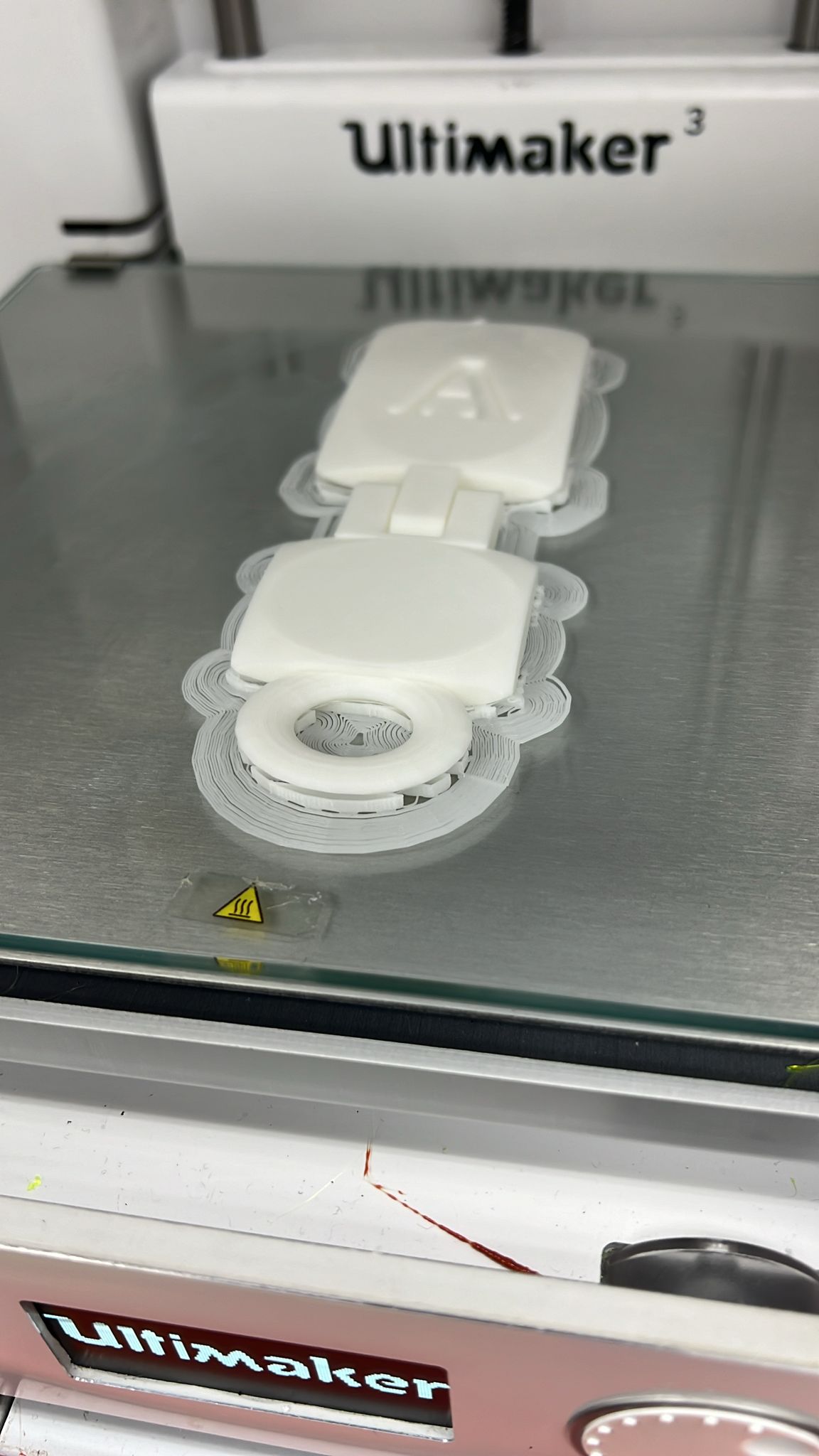 |
Start your 3D print | I Ensured the Ultimaker 3 is properly calibrated and the build plate is leveled before starting the print with your G-code. |
7. Example of Use 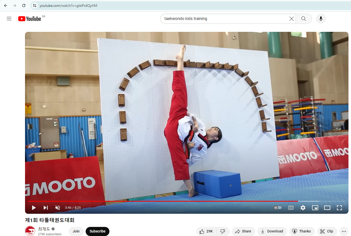
|
For Clubs | I want to use simple prints to entice youth to learn more for their daily activities. I cant find where to buy this. hence made it. The ball joint and print in one piece is not easily done by substractive manufacturing. |
I2. Workflow for Using Polycam on iPhone to Scan 3D Models
| Step | Description |
|---|---|
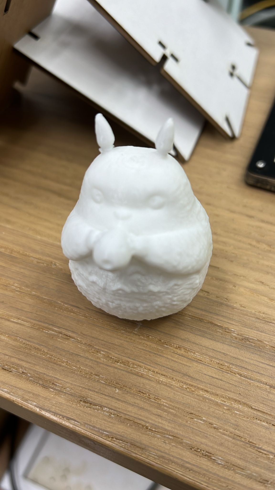
1. Prepare the Object
|
I Placed the object, I want to scan on a stable surface with good lighting. I ensure that the object is well-lit and evenly illuminated from all angles to capture details accurately. |
| 2. Open Polycam App | I Launched the Polycam app on your iPhone. |
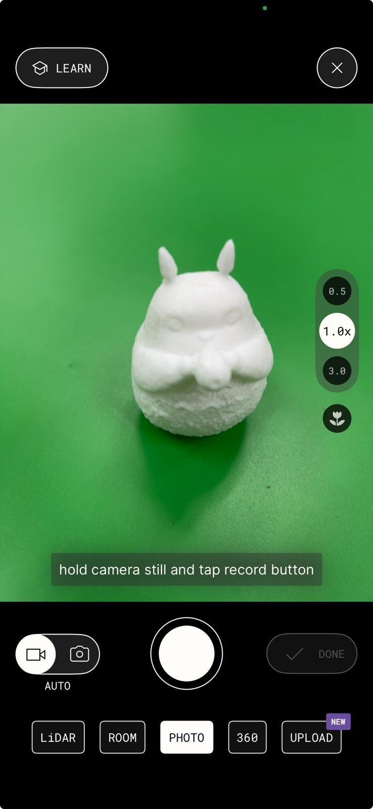
| 3. Start a New Scan | I Tapped on the "New Scan" button within the Polycam app to begin a new scanning session. I Positioned my iPhone so that the object fits within the frame of the camera view. |
4. Capture Reference Frame
|
I tap the "Start Scan" button to begin the scanning process. I slowly move my iPhone around the object, keeping it within the camera's view. |
6. Complete Scanning
|
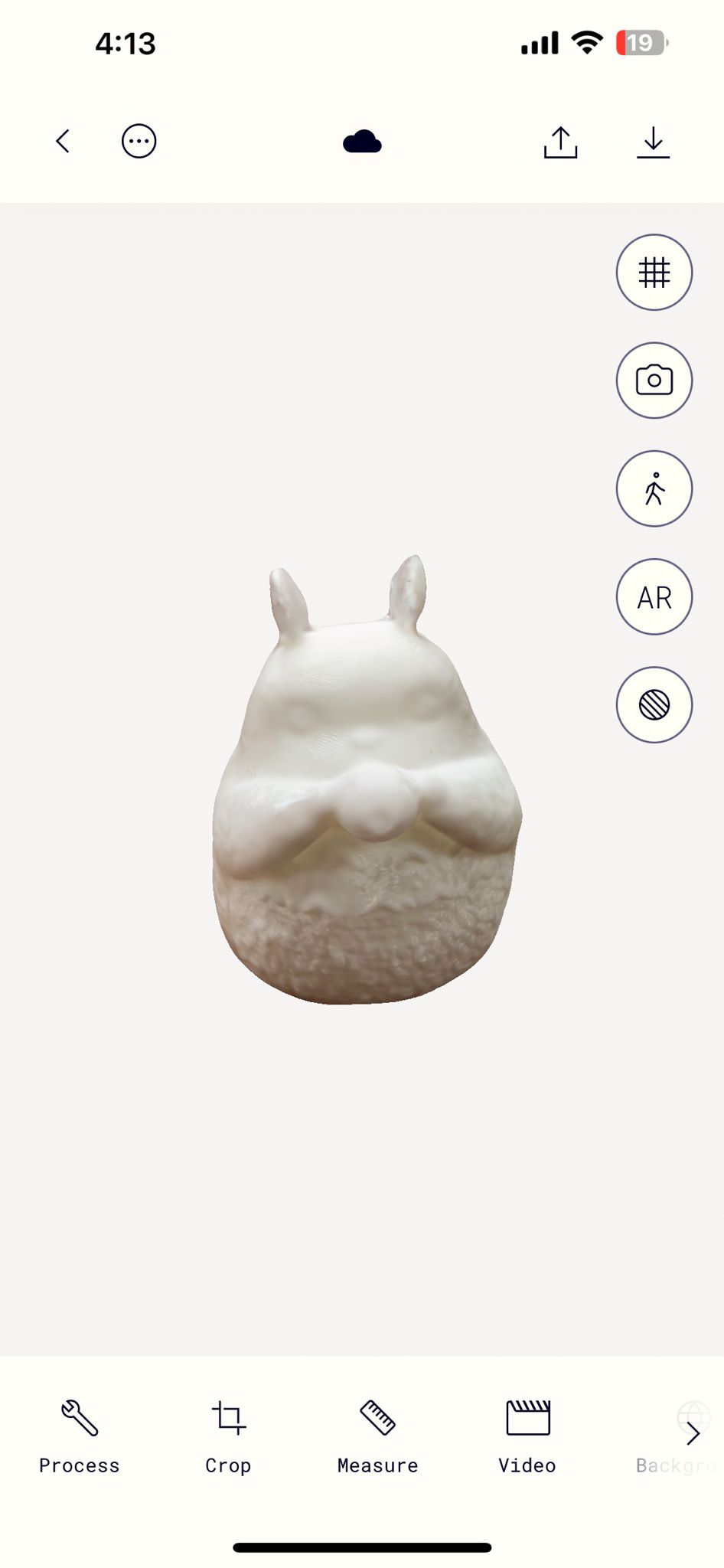
I continued scanning the object from various angles until I had captured all sides and details. Polycam automatically stitch together the individual scans to create a complete 3D model. |
| 7. Review and Edit | After scanning is complete, I reviewed the 3D model within the Polycam app. |
8. Save or Share the Model
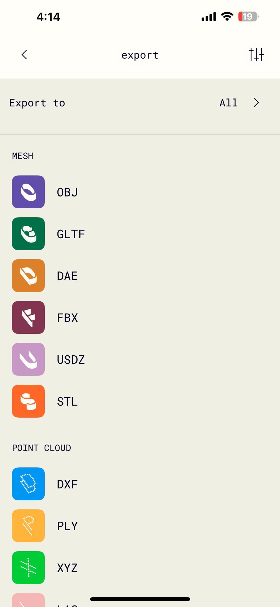
|
I Save it as GLTF to my iphone as it is the free option. |