4. Electronics production
4.1.1 Design rules for in-house PCB production by CNC mill(as group assignment)
Usually, PCB production process may start from circuit design and then pattern design.
Special softwares like Eagle or KiCAD are often used to design circuit patterns and Gerver files are their output.
I’m not famiiiar with these softwares yet at present, so I decided to use existing templates.
(I installed KiCAD for learning later)
![]()
![]()
There are various ways for in-house PCB production. One of them is CNC milling.
‘Roland SRM-20’ is one of the CNC mills in our lab. It is handy in size for PCB cutting. It uses the special milling software called ‘SRP Player’.
‘SRP Player’ uses STL(.stl) files as data source and convert them to special codes which are sent to the machine and used for milling jobs.

Technical data of SRM-20
| Cuttable Material | Modeling Wax, Chemical Wood, Foam, Acrylic, Poly acetate, ABS, PC board |
| X, Y, and Z Operation Strokes | 203.2 (X) x 152.4 (Y) x 60.5 (Z) mm |
| Workpiece table size | 232.2 (X) x 156.6 (Y) mm |
| Distance From Collet Tip to Table | 130.75mm Maximum |
| Operating Speed | 6 – 1800 mm/min |
| Spindle Rotation Speed | Adjustable 3000 – 7000 rpm |
| Cutting Tool Chuck | Collet method, adjustable up to 6 mm diameter |
| Control Command Sets | RML-1, NC code |
4.1.1.1 Data conversion
I choosed FabISP for the assigmnents of this week.
We can find a detailed description of FabISP in FabISP assembly tutorial. The tutorial is very comprehensive and really useful.
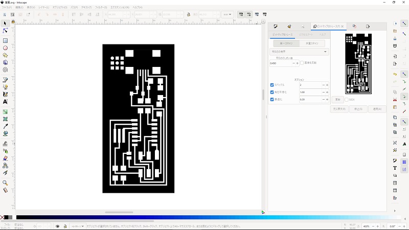
I downloaded a image file of FabISP circuit pattern from the tutorial and opened it by Inkscape.
I converted the image to vector data(called ‘pass’ in Inkscape) using ‘Trace bitmap’ funtion, and exported it as a SVG(.svg) file which can be handled with 3D-CAD softwares.
Data files:
hello.ISP.44.traces.png
hello.ISP.44.svg
4.1.1.2 Local design rules for CNC milling in our lab
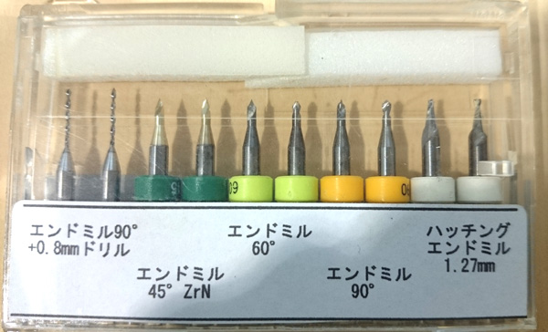
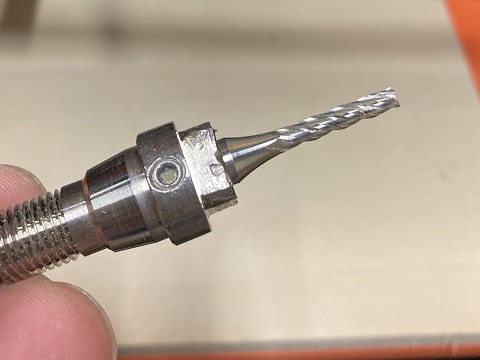
We have several end mills with various sizes and shapes in our lab.
Among them, I used 45 degrees conical mill for engraving ciruit pattern, 0.8 mm flat mill for cutting, and 3 mm flat mill for planing a waste board.
So I should consider the character of these mills for designing STL data.
45 degrees conical mill is good for engraving sharp pattern, but engrave depth shouldn’t be too much, otherwise mill hits side walls of the pattern.
0.8 mm flat mill is used for cutting, so cutting lines should be designed wider than the diameter of the mill.
3 mm flat mill or wider ones could be used for planing a waste board.
4.1.1.3 Creating STL data:
I imported the SVG data to Fusion 360.
I added the depth to the pattern and made a couple of STL files. One is for engraving and the other is for cutting.
Reflecting on the local rule described above, engraving depth were defined as 0.45 mm (thickness of copper-clad is said to be 0.1 mm).
Width of cutting lines were defined as 1 mm.


Data files:
hello.ISP.44_1.stl
hello.ISP.44_2.stl