Computer Controlled Machining
Make (design+mill+assemble) something big.
Group assignment:
Group Assignment
Choosing and measuring the material
I choose MDF 12mm for the assignment.
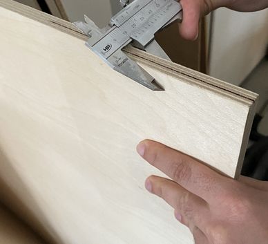 We measured the different materials the Lab has in stock. Most were
12mm.
We measured the different materials the Lab has in stock. Most were
12mm.  Since I want to paint my shelf later, we choose MDF as its easiest to
paint.
Since I want to paint my shelf later, we choose MDF as its easiest to
paint.
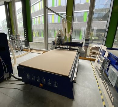 We carried the plate to the CNC
CAD and CAM in Fusion
Creating the test files in Fusion and preparing the toolpath:
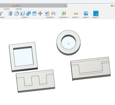 Create some simple test models. One to test joints, a circle for
runout, a
rectangle for alignment.
Create some simple test models. One to test joints, a circle for
runout, a
rectangle for alignment. 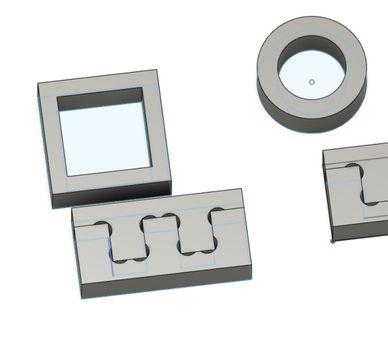 Add dogbones with the dogbone add-in (explained below) or by
hand.
Add dogbones with the dogbone add-in (explained below) or by
hand.
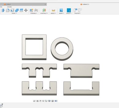 Align them (make sure they are at least the diameter of the tool away
from
each other)
Align them (make sure they are at least the diameter of the tool away
from
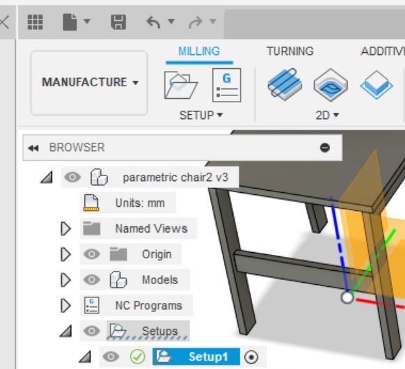
each other)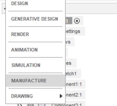 Go to the manufacture workspace
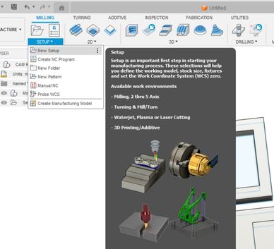 Create a new setup
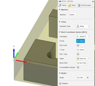 First to set is the orientaton (select Z and Y option) and the origin
(selected by hand, see pic)
First to set is the orientaton (select Z and Y option) and the origin
(selected by hand, see pic)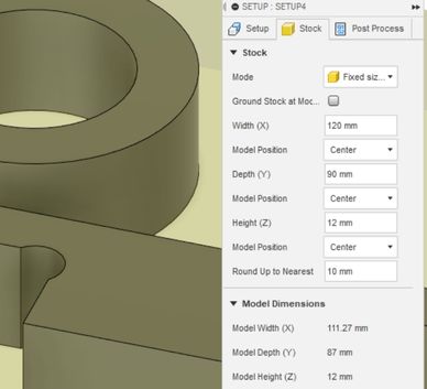 Now adjust the stocksize. The material I'm using is 12mm thick. Hit ok
for
the setup
Now adjust the stocksize. The material I'm using is 12mm thick. Hit ok
for
the setup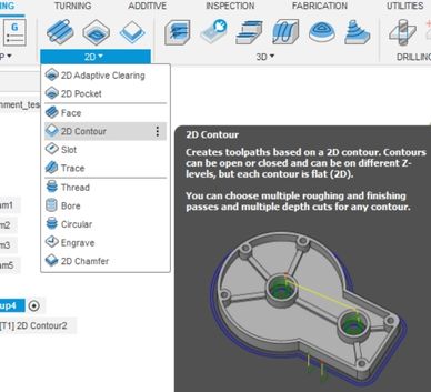 Select 2d contour as the toolpath
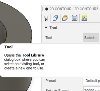 Select tool
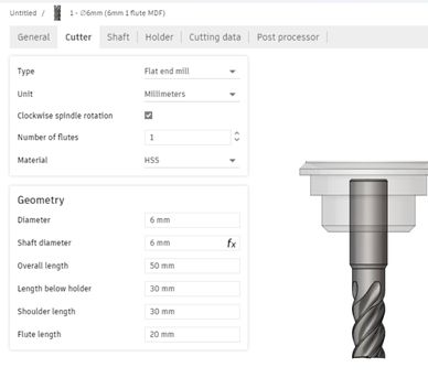 If you need to make a new
one, click the plus and this window will appear.
Add the dimensions of your flute
If you need to make a new
one, click the plus and this window will appear.
Add the dimensions of your flute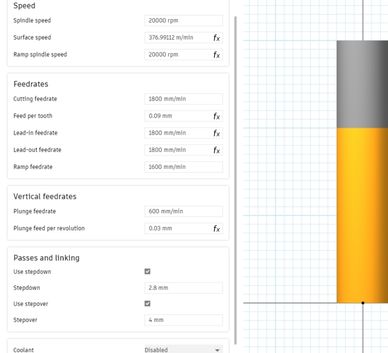 Adjust the cutting data to your needs
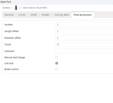 Set this to 1
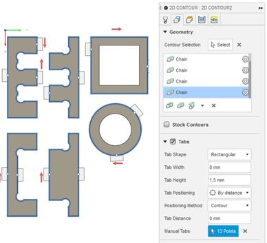 After you added the
tool,
select the edges to mill (make sure to select the bottom ones)
After you added the
tool,
select the edges to mill (make sure to select the bottom ones)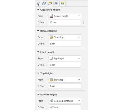 Set the bottom height
offset to -0.2mm to fully cut through the material
(make sure that there is a sacrifical layer of wood on your cnc that yo can cut into
underneath)
Set the bottom height
offset to -0.2mm to fully cut through the material
(make sure that there is a sacrifical layer of wood on your cnc that yo can cut into
underneath)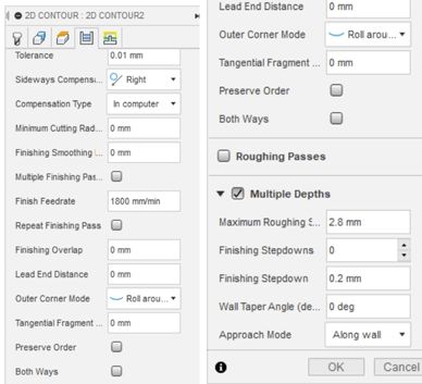 Set the sideways
compensation to right and the maximum roughing stepdown to about a fourth of the
material thickness
Set the sideways
compensation to right and the maximum roughing stepdown to about a fourth of the
material thickness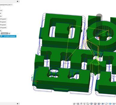 If you hit ok now, it should look somewhat like this
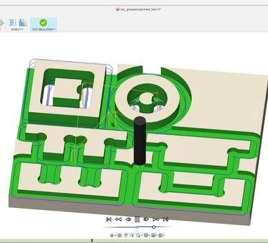 You can simulate the toolpath now (Actions>Simulate)
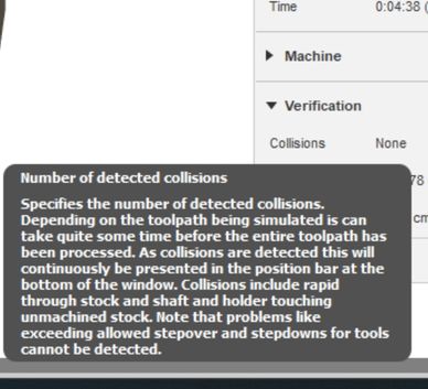 No collision should
occur. You might need to change your tool settings otherwise.
No collision should
occur. You might need to change your tool settings otherwise.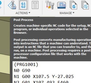 If you are happy with
the path, you can hit post process
If you are happy with
the path, you can hit post process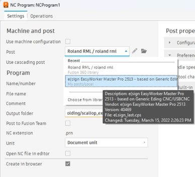 Select the
post-processor of your cnc (usually needs to be downloaded first) and choose a
location to save. Click Post.
Select the
post-processor of your cnc (usually needs to be downloaded first) and choose a
location to save. Click Post.Test results
Now that the models
 Break the tabs to release the model
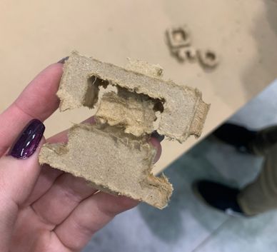 The result is rather bad, very jagged edges. This is because the tool
is already quite old. For my actual shelf, I will use a sharper tool.
The result is rather bad, very jagged edges. This is because the tool
is already quite old. For my actual shelf, I will use a sharper tool.
 All cutouts
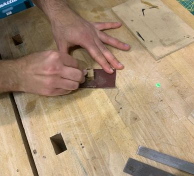 Sanding the edges to smooth them out
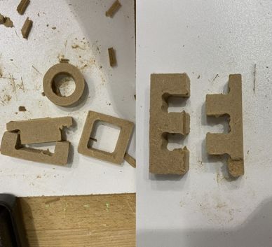 The cleaned models. Some edges weren't accessible with the sanding
paper and some other parts broke off. The parts are very small and these problems
wouldn't occur on a much larger scale
The cleaned models. Some edges weren't accessible with the sanding
paper and some other parts broke off. The parts are very small and these problems
wouldn't occur on a much larger scale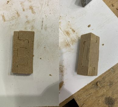 The joints fits together verywell. I did not create any offset
for these. But the MDF is rather "soft" so I could easily hammer them in place.
For future designs I'll add a small offset (about 0.075mm per side) just to be on
the safe side.I will test this again before cutting my actual design.
The joints fits together verywell. I did not create any offset
for these. But the MDF is rather "soft" so I could easily hammer them in place.
For future designs I'll add a small offset (about 0.075mm per side) just to be on
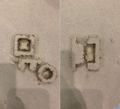
the safe side.I will test this again before cutting my actual design.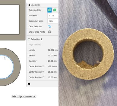 The circles inner
diameter is 20mm in Fusion and it's also 20mm in the cut part. So there is no runout
in the tool. It's center and the spinning axis are aligned.
The circles inner
diameter is 20mm in Fusion and it's also 20mm in the cut part. So there is no runout
in the tool. It's center and the spinning axis are aligned.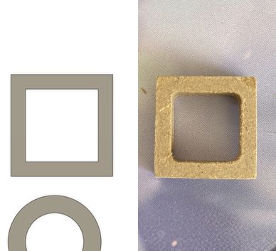 For the square the inner corners are rounded off. This was to be
expected, as the tool diameter is 6mm. The angle is 90°, so no alignment issues with
the machine
For the square the inner corners are rounded off. This was to be
expected, as the tool diameter is 6mm. The angle is 90°, so no alignment issues with
the machineDesign in Fusion360
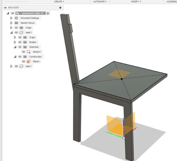
I designed a chair, following this tutorial.
 Next up are the legs. I
designed the left side first, already integrating the parts where I will stick it
together.
Next up are the legs. I
designed the left side first, already integrating the parts where I will stick it
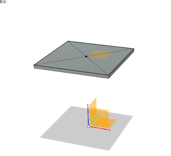
together.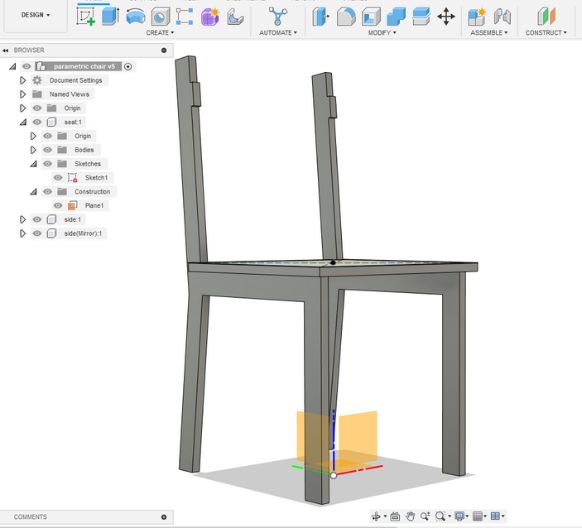 Using construction
planes and the mirror tool Icopy the right leg.
Using construction
planes and the mirror tool Icopy the right leg.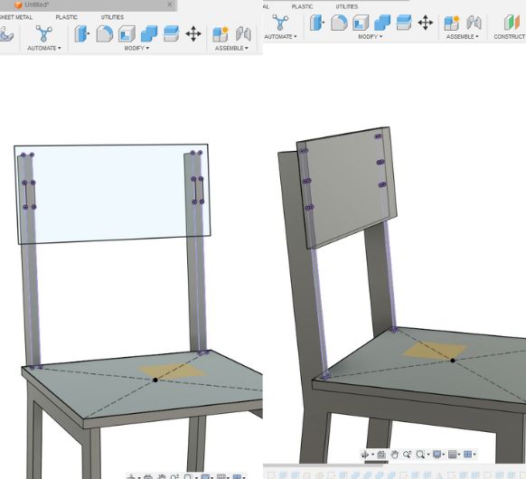 Adding the back plate
:)
Adding the back plate
:)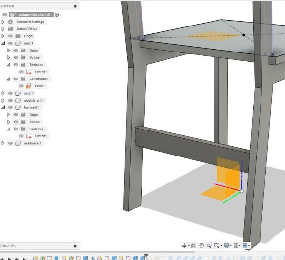 Forstability, I am
adding these braces.
Forstability, I am
adding these braces. 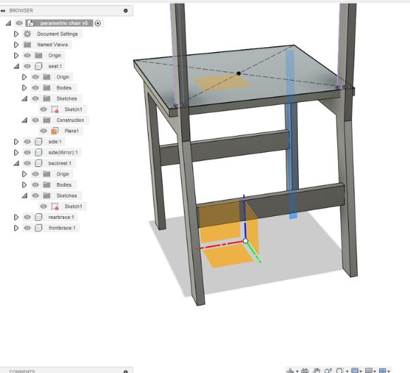 Front and back.
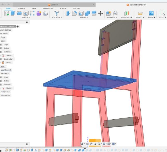 I still need to cut
some pockets into the backplate and the sitting plate.
I still need to cut
some pockets into the backplate and the sitting plate.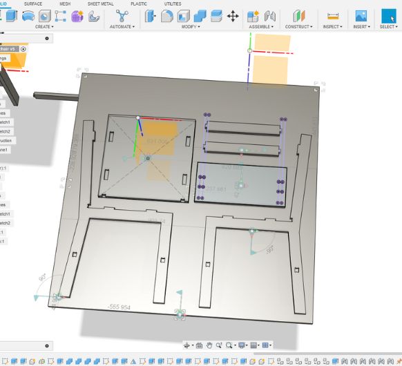 Lastly I am arranging
the components on a plate that has the size of the wood I'll be using.
Lastly I am arranging
the components on a plate that has the size of the wood I'll be using.Adding dogbones
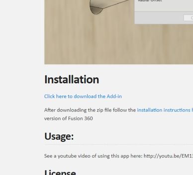
Now we I need to add dogbones to all my inner corners. This needs to be done, because the milling tool has a cylindrical shape and a certain diameter, therefore there cannot be any sharp inner corners in the design. I followed this tutorial to install a add-in for fusion which adds dogbones automatically. Follow this link: http://tapnair.github.io/Dogbone/ and install the add-in:
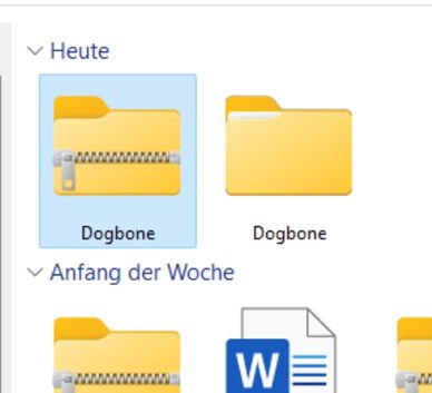 Extract all the files and rename the folder to just "Dogbone". Ctrl+C
the
folder.
Extract all the files and rename the folder to just "Dogbone". Ctrl+C
the
folder.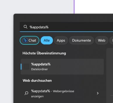 Head over to your AppData folder.
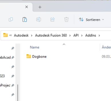 Open: Autodesk > Autodesk Fusion 360 > API > AddIns and then paste
the Dogbone folder there
Open: Autodesk > Autodesk Fusion 360 > API > AddIns and then paste
the Dogbone folder there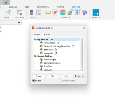 (Re-)Start Fusion. Head to Utilities and open Add-Ins. Click on the
green plus to add a new one.
(Re-)Start Fusion. Head to Utilities and open Add-Ins. Click on the
green plus to add a new one.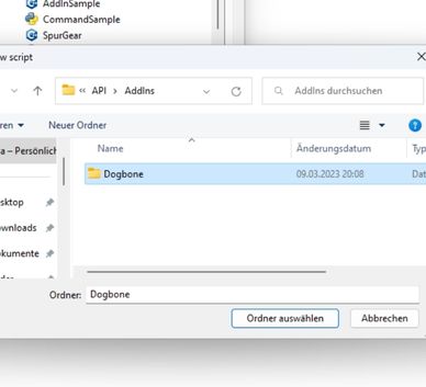 Select the Dogbone folder inside the master folder and add it
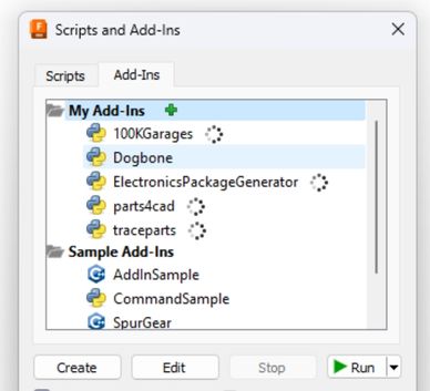 It will now appear in the list
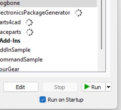 Activate the checkmark and hit Run
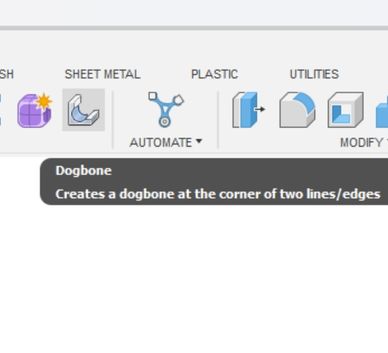 Now, in the solid workspace, you will find this Dogbone tool
CAM Toolpath
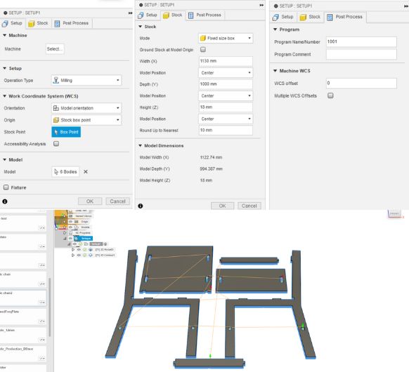 Apply all of the
needed settings for the setup.
Apply all of the
needed settings for the setup.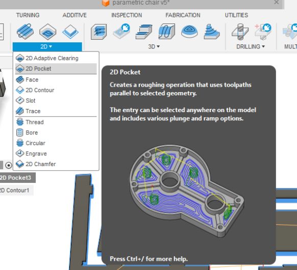 The first thing that
will be cut are the pockets. So I am starting with 2D pocket.
The first thing that
will be cut are the pockets. So I am starting with 2D pocket.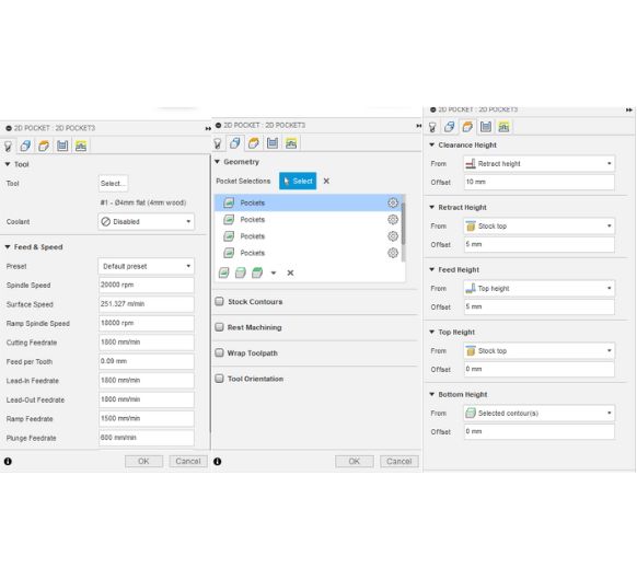 These are the
settings. Make sure you select all the pockets in you model.
These are the
settings. Make sure you select all the pockets in you model.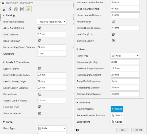 Last two setting pages
of 2D pockets.
Last two setting pages
of 2D pockets.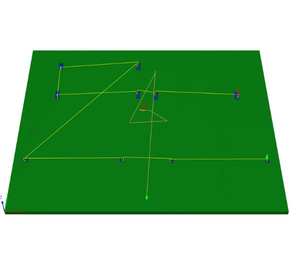 Here you can see the
toolpath which the machine will take. You see all of the pockets being
milled.
Here you can see the
toolpath which the machine will take. You see all of the pockets being
milled.
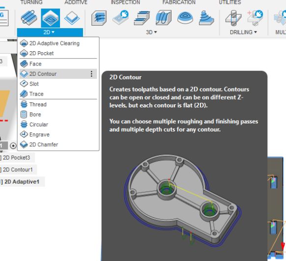 I still need to do the
edge cuts though. 2D contour is the optimal tool for this.
I still need to do the
edge cuts though. 2D contour is the optimal tool for this.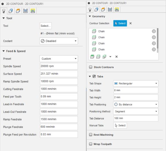 I am setting a 4mm
flat end mill as the tooland select all the edges.
I am setting a 4mm
flat end mill as the tooland select all the edges.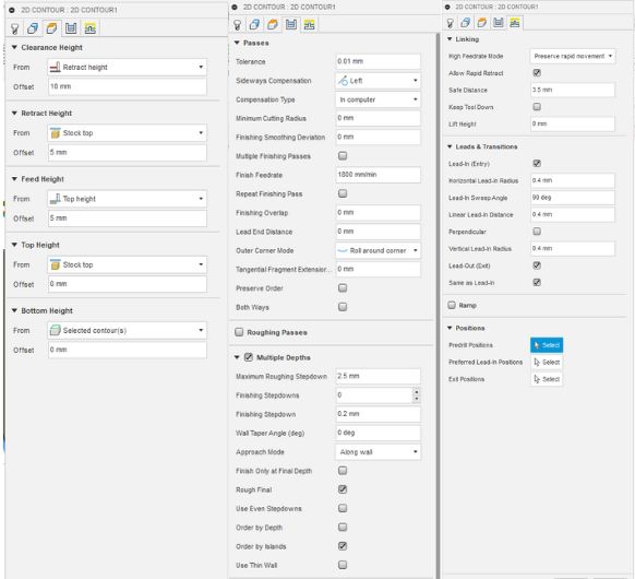 Here I am setting the
Passes settings and so on.
Here I am setting the
Passes settings and so on.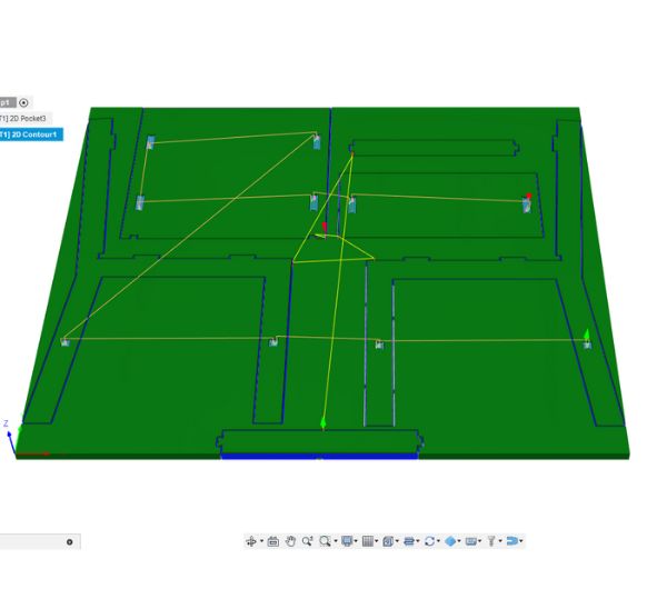 Also here, you can see
what the toolpath looks like.
Also here, you can see
what the toolpath looks like.Export this and go to your CNC.
Download my Fusion project file
Operating the big CNC
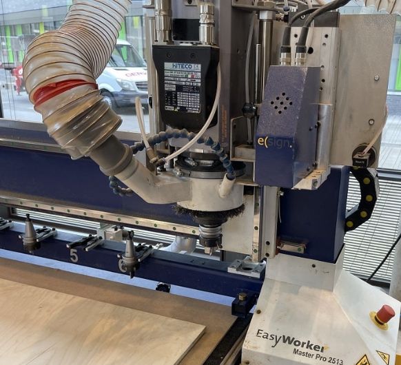
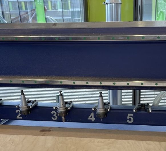 The tool holder
 valve for the high
pressured air
valve for the high
pressured air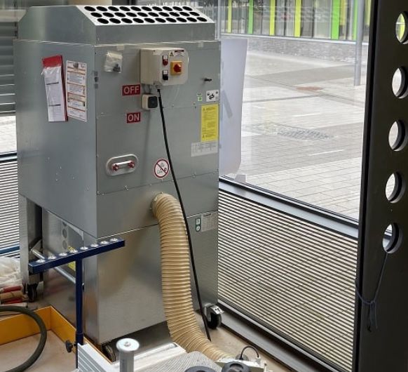 The extraction station
with the On/Off switch
The extraction station
with the On/Off switch The control station for
the extraction pipes (This is there because
there are multiple machines connected to the extraction, and to get the best pull to
the extraction station, the ways to the other tools can be closed electricly)
The control station for
the extraction pipes (This is there because
there are multiple machines connected to the extraction, and to get the best pull to
the extraction station, the ways to the other tools can be closed electricly)
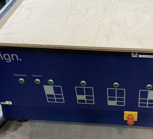 And the vacuum bed
control. A compressor creates the vacuum for the
bed.
And the vacuum bed
control. A compressor creates the vacuum for the
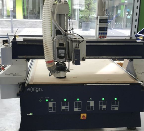
bed.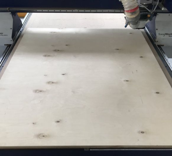 In order to operate the
milling machine, we first loaded the bed with
the material we wanted to mill. In my case this was a circa square sheet of wood
with 12mm thickness. Under this sheed of wood was a sacrificial layer of MDF.
In order to operate the
milling machine, we first loaded the bed with
the material we wanted to mill. In my case this was a circa square sheet of wood
with 12mm thickness. Under this sheed of wood was a sacrificial layer of MDF.
After
loading the stock, it's time to prepare the CNC:
- Start the PC.
- Press the green start button after the program has started.
- Start the machine after the program and stop the machine before closing the program to avoid information discrepancies.
- Incorrect order of operation can lead to the mill crashing into the tool swapping station. The CNC lacks collision detection and could be damaged in such a scenario.
When zeroing the z-axis,
the machine offers multiple automatic processes. Firstly, the
machine can determine the length of the current tool automatically using a sensor
located at the back. Secondly, the Gantry is equipped with a zeroing sensor similar
to
our Roland MDX-40. This step requires the assistance of
two individuals. One person holds the zeroing sensor while the other initiates the
process, keeping a finger on the escape button or the emergency stop in case any
issues
arise. The escape button serves as an immediate stop for the machine's
operation.- Let's begin the milling process. Firstly, we ensured our safety by wearing earbuds and protective eye gear.
- Next, we proceeded to open the high-pressure air valve.
- Then, we started the vacuum bed with all neccessary vacuum zones active.
- Following that, we activated all the necessary vacuum zones to start the vacuum bed.
- Lastly, we initiated the exhaust system while confirming if the exhaust to the mill was either closed or open, considering that other connected machines might have been used.
- Once these preparations were completed, we loaded the toolpath that was created in Fusion360. After carefully reviewing the projected job in the software, we commenced the milling process either by clicking the "start" button in the program
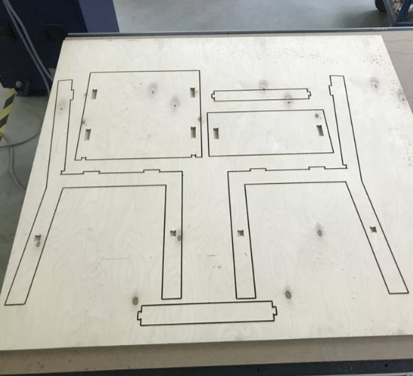 -This is what it looked like after milling. There were no big
complications while cutting.
-This is what it looked like after milling. There were no big
complications while cutting.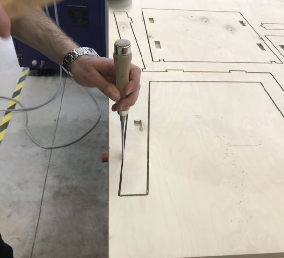 Ahmed helped me break the tabs. I also sanded the edges a bit.
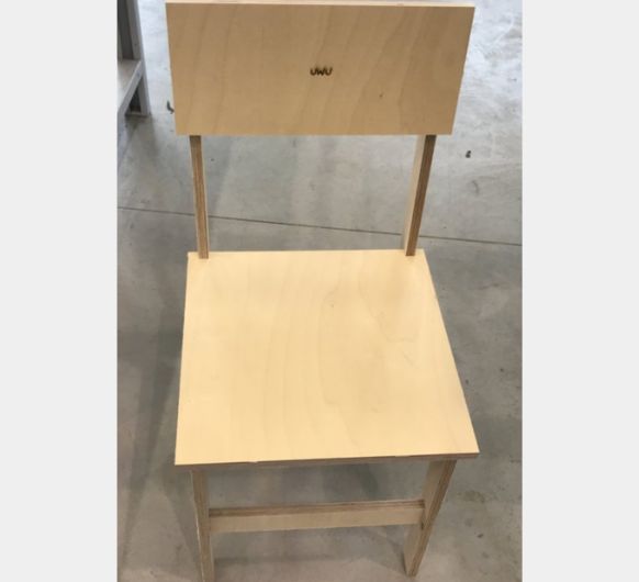 And lastlyI assembled the chair. I had to use a hammer to get
everything together. But now that it fits it's so tight it's making the chair very
stable. I have already stood on it and itdidn't wiggle.
And lastlyI assembled the chair. I had to use a hammer to get
everything together. But now that it fits it's so tight it's making the chair very
stable. I have already stood on it and itdidn't wiggle.