
Assignment 11 - Output Devices
Individual Assignment
- Add an output device to a microcontroller board you've designed, and program it to do something
Group Assignment
- Measure the power consumption of an output device
Assignments
Group Assignment
The Group Assignemnt page for thsi week can be found here.
Individual Assignment
For this week, I really wanted to do something with stepper motors, as I would need them for my final project. Since I already had a look into LEDs and managed to do a pretty cool Board that doubles as a two player game in Embedded Programming Week, I fully concentrated myself on the stepper motor. As a Goal for this week, I wanted to simply drive the Motor through my Big Cat Board, which would accept Commands through Serial and move the Motor according to the received Commands.
First things first was the electrical connection. The stepper motor needs a stepper driver. I got a Silent Step Stick from our Inventory and checked the Documentation of the Chip as well as the informations on the Board itself. After reading into the documentations, I began connecting the stepper driver Board. to my Big Cat in the following way:
- Driver Board Enable connected to free Digital Pin 1 on Cat Board
- Driver Board Direction connected to free Digital Pin 2 on Cat Board
- Driver Board Step connected to free PWM pin 1 on Cat Board
- VMotor of Driver Board connected to 12V line from power supply
- Stepper Motor Black and Green to M1A and M1B of stepper driver
- Stepper Motor Red and Blue to M2A M2B of stepper driver
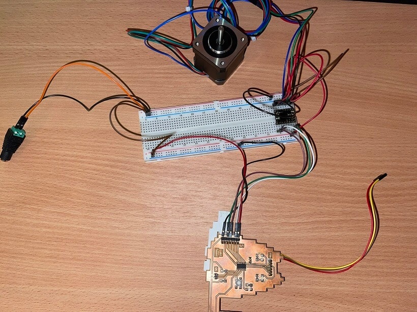
The motor itself was connected like showcased here. With all of the prerequisites done, I began programming. Without anything connected to them, the CFG pins of the steper driver Board tell the MCU on the Board to use the maximum amount of microsteps available. For my program, I wanted to be able to set distinct features through commands sent via serial. For this I wrote a very wonky "parser" to take in commands. It basically just listens for keywords, splits the keyword itself from the incoming string and converts the numbers after the keyword to usable values. These values would then be used when the program was told to start the motor with the values provided. This resulted in the following Code:
int enable = 3; //Pin on my Board that goes to enable on stepper driver
int dir_pin = 2; //Pin on my Board that goes to dir on stepper driver
int step_pin = 0; //Pin on my Board that goes to step on stepper driver
int led = 10;
String cmd = ""; //Variable to hold received command
byte bfr = ' '; //
bool execute = false; //execute bit to trigger command execution
int rotDeg = 0.0; //Variable to hold the degrees to be rotated when the final command is executed
short stepperSpeed = 1000; //Variable to hold the speed with which to execute the command
int nmbrOfExecs = 0; //Variable to hold the number of executions of the command
bool dir = 0; //Helper Variable to store the direction for the command execution

void setup() {
	Serial.begin(115200); //start Serial communication
	pinMode(enable, OUTPUT); //Set enable Pin as OUTPUT
	pinMode(dir_pin, OUTPUT); //Set direction pin as OUTPUT
	pinMode(step_pin, OUTPUT); //Set Step Pin as OUTPUT
	pinMode(led, OUTPUT); //LED on my own Board

}

void loop() {
	digitalWrite(enable, HIGH);
	if(Serial.available()){ //Check if incoming data is available
		cmd = Serial.readString(); //Read incoming Data as String

		//"Parse" the String (Very crude parsing)

		//If command starts with execute, set execute bit and start timer if number was given as argument
		if(cmd.startsWith("execute ")){
		cmd.remove(0,8);
		int tmp = cmd.toInt();
		if(tmp < 0){
			tmp = 0;
		}
		Serial.print("Waiting for ");
		Serial.print(tmp);
		Serial.println(" Milliseconds");
		delay(tmp);
		Serial.println("executing...");
		execute = true;

		//If command starts with speed, parse rest of message as speed mapped [0 - 10] and map it to speeds [1000 - 2000]
		}else if(cmd.startsWith("speed ")){
		cmd.remove(0,6);
		int tmp = cmd.toInt();
		if(tmp > 10){
			tmp = 10;
		}else if(tmp < 0){
			tmp = 0;
		}
		stepperSpeed = map(tmp, 10, 0, 1000, 2000);
		Serial.print("Set speed to: ");
		Serial.print(tmp);
		Serial.println("!");

		//If command is help, explain all commands
		}else if(cmd.startsWith("help")){
		Serial.println("execute [value] - Start motor operation wit delay of value in milliseconds");
		Serial.println("speed [value] - set speed to value (0 - 10)");
		Serial.println("rot [value] - Set rotaion amount (0 - 360)");
		Serial.println("nmbr [value] - Number of executions to do");
		Serial.println("dir [value] - Sets spin direction (o - ctr, 1 - clk)");

		//If command starts with rot, parse rest of message as degrees to rotate (maxed at 360)
		}else if(cmd.startsWith("rot")){
		cmd.remove(0,4);
		int tmp = cmd.toInt();
		if(tmp > 360){
			tmp = 360;
		}else if(tmp < 0){
			tmp = 0;
		}
		rotDeg = map(tmp, 0, 360, 0, 200); //Map from 0-360 to 0-200 because of 1.8 degree step angle
		Serial.print("Set rotation to: ");
		Serial.print(tmp);
		Serial.println(" Degrees!");

		//If command starts with nmbr, parse rest of message as number of executions
		}else if(cmd.startsWith("nmbr ")){
		cmd.remove(0,5);
		int tmp = cmd.toInt();
		if(tmp < 0){
			tmp = 0;
		}
		Serial.print("Set number of executions to: ");
		Serial.print(tmp);
		Serial.println("!");
		nmbrOfExecs = tmp;

		//If command starts with dir, parse rest of message as bool to set direction of rotation
		}else if(cmd.startsWith("dir ")){
		cmd.remove(0,4);
		int tmp = cmd.toInt();
		if(tmp > 1){
			tmp = 1;
		}else if(tmp < 0){
			tmp = 0;
		}
		Serial.print("Set direction to: ");
		Serial.print(tmp);
		Serial.println("!");
		dir = tmp;
		}
	}

	//If execute bit is true => Execute command with current settings
	if(execute){
	digitalWrite(enable, LOW);
	digitalWrite(led, HIGH);
	digitalWrite(dir_pin, dir);
	digitalWrite(step_pin, LOW);
	for(int j = nmbrOfExecs; j > 0; j--){
		for(int i = 0; i < rotDeg; i++){
		digitalWrite(step_pin, HIGH);
		delayMicroseconds(stepperSpeed);
		digitalWrite(step_pin, LOW);
		delayMicroseconds(stepperSpeed);
		}
	}
	execute = false;
	}else{
	digitalWrite(enable, HIGH);
	digitalWrite(led, LOW);
	}
}
As you can see in the Code, the program, listens for specific keywords, namely: help, execute, rot,
nmbr, speed and dir. All of these keywords can then sent to the Board with Values attached to them
like so: "keyword value". If the user ever wants to see all possible commands, the USer ca just send
help and the program will print out all of the available commands. Now onto what the
single keywords actually do:
Like I already mentioned help can be used if the User wants to get a comprehensive List of all available commads and all of the minimum and maximum values attached to each of the available commands.
If the User wants to use the rot command to set the amount of rotation the stepper
motor should do, the user ca do so by typing rot 360 for example. This command is (for
now) capped to 360 degrees, hence the max value of 360. This is the User side of this command. What
happens internally is a little bit different. While the User wants to specify the rotation in
degrees, the motor driver wants to know, how many steps it should do to achieve this rotation.
Through the datasheet of the Motor I am using, I
could read up, that each full step resulted in a moved angle of 1.8°. This on the other Hand means
that a
full 360 degree rotation would be done in 200 steps using full steps. THis is why, when you take a
look at the code
above, I use the mapping function to map from between 0 and 360 degrees to between 0 and 200 steps.
So while the use can send in the degrees of rotation the user woulod like to achieve, the program
uses calculated steps internally.
For speed, I had to test around quite a bit to find usable values. As with the rotation, the User
can simply type something like speed 5 for the program to set the speed to the users
wanted value. Whats special for the speed, is again the internal calculation of the speed. The speed
of the motor is determined by the delay between the HIGHs and LOWs of the step pin. The lower this
delay is, the faster the motor gets. This is why, when the user chooses a speed (between 0 and 10),
a calculation has to take place, to make the user speed of 10 the lowest delay number, while the
user speed of 0 has to correspond to the higjest delay number. Naturally a User would think, that 10
is faster than 0, so I had to map the other way around compared to the rotation. I mapped the value
from 10 to 0 to the range of 1000 to 2000. This means a max value of 10 would result in the number
1000 and a min value of 0 would result in a mapped value of 2000.
The direction was by far the easiest setting to create. The direction pin of the stepper driver can
either be HIGH or LOW, depending on the direction the motor should move, so either HIGH means
clockwise and LOW means counterclockwise or the other way around. For my specific Stepper driver, I
just tested around and found out that HIGH was rotating the motor clockwise, while LOW klet the
motor rotate counterclockwise. So when the user send the command dir 1, the direction
will be set to clockwise and if the user sets it to 0 it will be moving counter clockwise.
The seeting for the numbers of executions the user wanted to have, was as simple as the direction setting. I just had to make sure no negative numbers would be allowed. This number simply repeats the main cycle as many times as it itslef is showing. So if the motor is set to 360 degrees of movement with 1500 speed and a direction of clockwise and the number of executions is set to two, the program will tell the driver to let the motor spin 360 degrees (200 steps) two times in a row, resulting in a movement of 720 degrees total.
Finally, the execute command. Here the user can also add a value to the command enabling a timer
that ticks down until the execution eventually starts when the timer hits 0. I wanted to have this,
since it was very difficult to see whats happening when on the press of enter the motor started
moving immediatly. I wanted to have the option to set a delay between the command being sent and the
command being executed. The user can for example simply type execute 1000. This would
then set the flag for the execution of the movement using all previous settings, as well as start a
delay with the value that comes after the execute keyword. In this case the delay would have been
1000, so rougly one second. After the movement is executed, the flag is reset.
The movement itself is also quite simple. Firt of, I set the enable pin to LOW. LOW means that the
motor should be enabled, while HIGH means that the motor is not enabled. This can all be read in the
datasheet of the stepper driver MCU. Next up, I enable the built in LED on my big cat Board. I do
this just for visibility and debugging. If the LED is turned on, I know that the motor should be
moving right now. After this I set the direction pin output to what the user set it to or to the
standard value initialized at the top if the User never set this value. Then I set the step pin to
LOW to prepare it to be set to HIGH inside the for loop. Then comes a nested for loop I already
mentioned above once. The outer loop is the number of executions. This loop will be gone through as
many times as the nmbrOfExecs variable tells it to. The inner for loop is the actual
movement, here the step pin wil be switched between HIGH and LOW repeadetly. The for loop itself
will be executed as many times as the calculated steps fromt the rotation setting, so each step of
the motor is one cycle of the inner for loop. between the HIGH and LOW and then again the next HIGH
of the step pin are microdelays with the value the user specified (which was then inetrnally mapped)
with the speed command. If both for loops are finished, the execute flag will be reset and the user
can again change the settings or execute the code again.
Sadly I never made a Video of this code working properly, since I just quickly thre it together to work on machine week, which I did alone in the end sadly. Right now I cannot get a video sadly, sice my power supply at home does not deliver enough Amps to drive the stepper motor I have with me here. I am also sadly stuck at home due to my Covid-19 infection at the moment. When I am at the Lab the next time, I will simply make a quick video of this code working (Which it does, but I forgot to record it D:)
So... As soon as my health allows it => Video will be posted here
Update: Im still in quarantine, but I ordered another PSU with enough power to drive the motor! And after swapping out the PSU and the (probably faulty) Stepper driver I finally could record the motor moving!
As you can see altough I typed in 360 degree rotation, the motor moved only a fraction of that. This is due to the microstepping setting of the driver being set to its maximum of 1/16 microsteps. With this setting the motor runs really smooth though, so i just let it run this way. To circumvent not going a full circle with the setting I used, I just had to set the mapping function from 0-360 <-> 0-200 to 0-360 <-> 0-3200 where 3200 of the 1/16 microsteps would mean a full rotation! Just to be sure I tested it and this was the result: