Week 5 3D scanning and printing

Assignments:

Group assignment:

    • Test the design rules for your 3D printer(s).
    • Document your work and explain what are the limits of your printer(s) (in a group or individually).
    • Document your work to the group work page and reflect on your individual page what you learned.

Individual assignment:

    • Design and 3D print an object (small, few cm3, limited by printer time) that could not be easily made subtractively.
    • 3D scan an object, try to prepare it for printing (and optionally print it) .

Learning outcomes:

    • Identify the advantages and limitations of 3D printing.
    • Apply design methods and production processes to show your understanding of 3D printing.
    • Demonstrate how scanning technology can be used to digitize object(s) .

image

Weekly practice

Reasearch

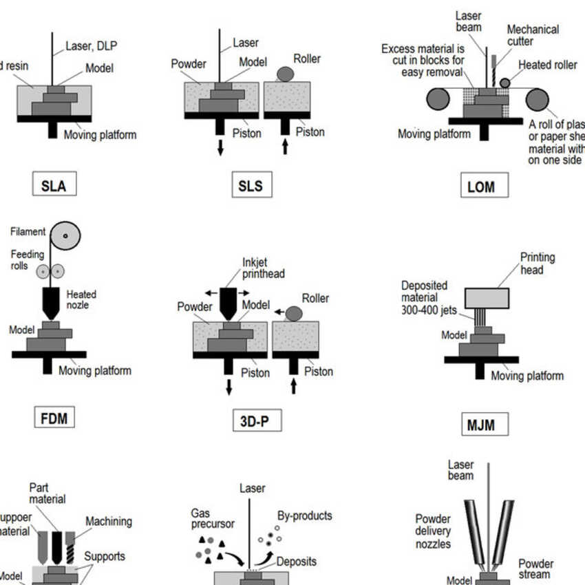
This was very really exciting and the most awaited week, as a 3d printer enthusiast I wanted to dive into this field systematically. Big thanks to junior instructor Noha which elaborated and guided me with sharing resources and useful links for doing research. I explored first of all printing technologies, type of 3d printers. And I found out that the name 3d printer is a huge umbrella which consists of many different types/ technologies.
Prof. Neil mentioned printing farms. I had very little idea about it before but after seeing all these types/technologies I wish to have a printing farm and all different types/technologies also.
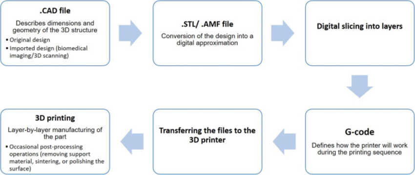
The concept between all these types/technologies are the same.
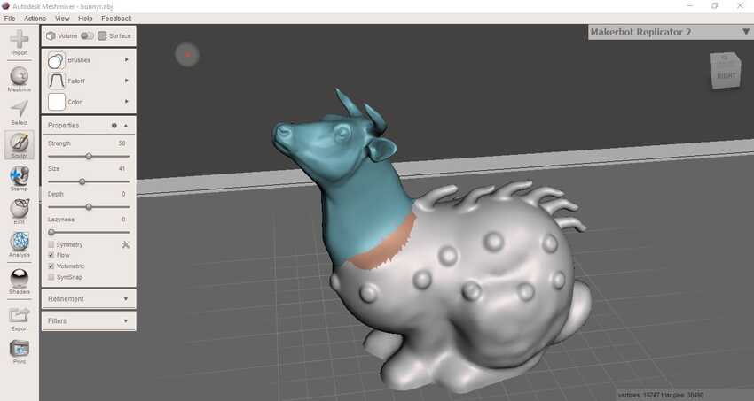
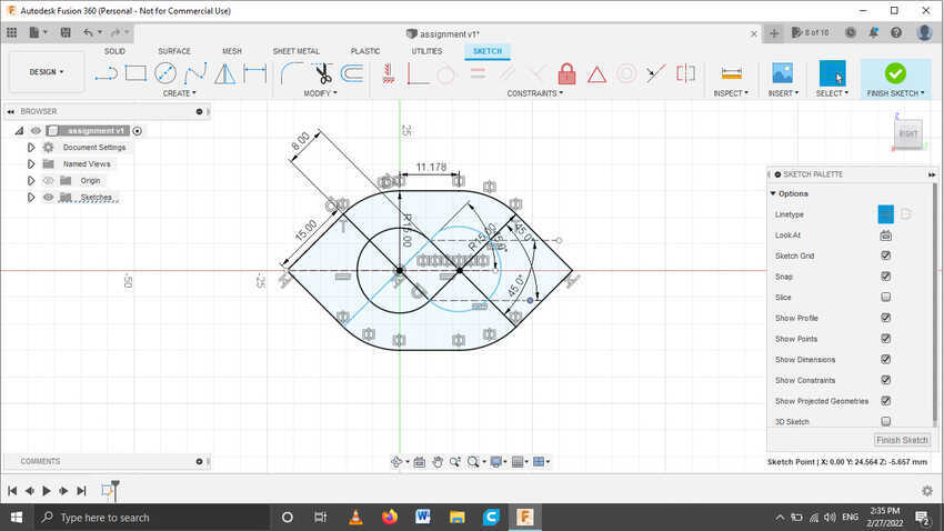
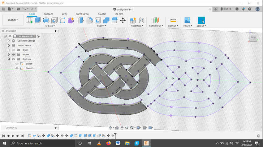
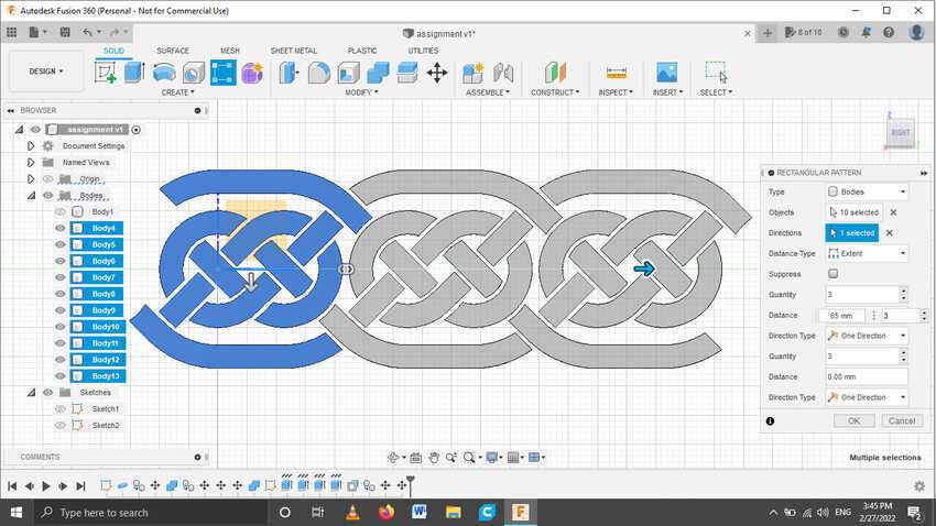
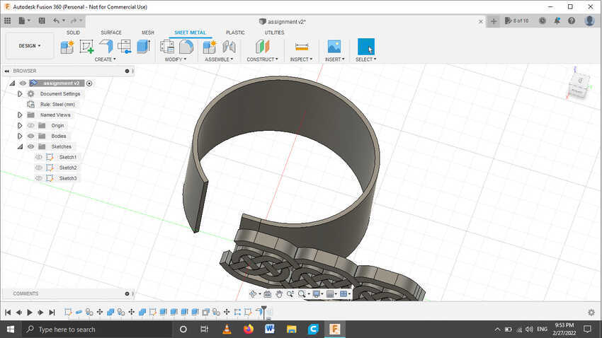
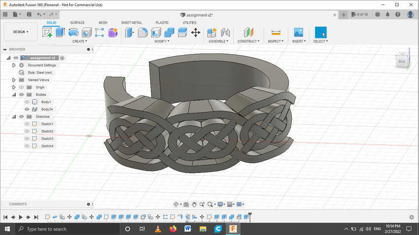
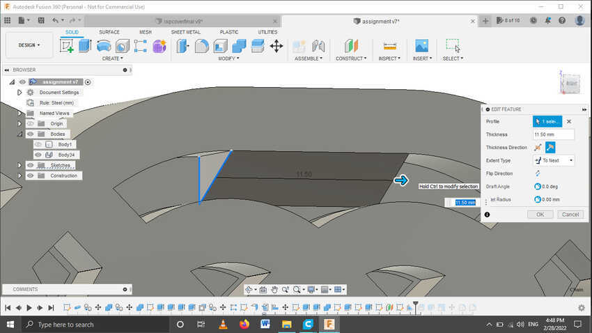
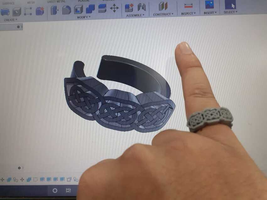
1) CAD: designing process (exporting them to .STL file or any other 3d format which support the CAM machine software).
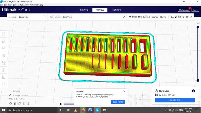
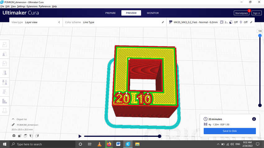
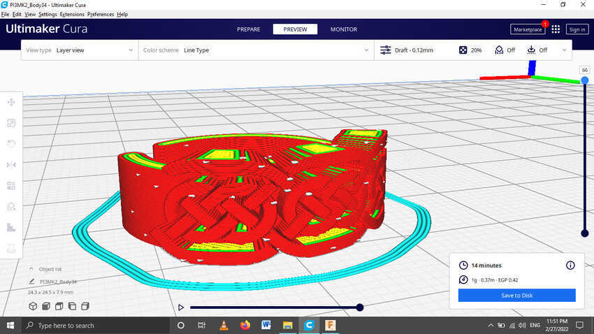
2) CAM:Exporting G-code from the slicer software and transferring it to the machine.
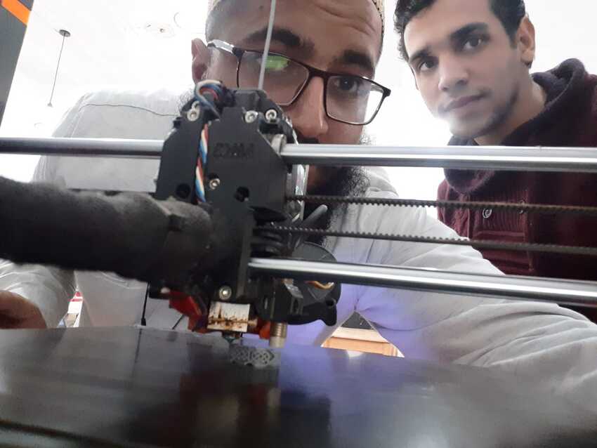
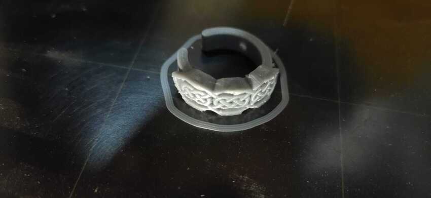
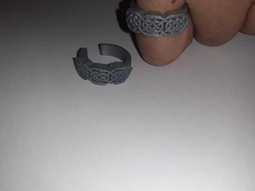
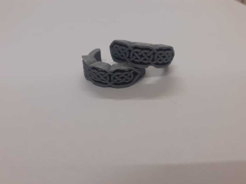
3) fabrication process: layer by layer 3d printing additive process.

image
image

I moved on to the materials for fdm only as it is the closest one and which will be used in my fab academy journey. As an enthusiast I kind of knew the basic information - little information and differences between popular materials. So I just skimmed and moved on to the main part, characterizing the machine’s parameters. Thanks to the class notes, all .STL and .PNG files were present which helped me to understand the parameters and use the .STL files for slicing in the group assignment.
I practiced designing a cover case for my FAB ISP pcb board, which had to meet these requirement:
1) Apply 3D printing design rules.
2) Parametric (Define parameters for Machine characteristics).
3) Include 1 Type at least of detachable joints (snap , …)
Because of the excitement I went on to design a complex enclosure rather than a simple one which ended in consuming too much time in designing this enclosure. I wanted to design 2 types of detachable joints: a hinge, ball screw joint type, which I was inspired by this box.
It was a nice experience to apply 3d printing rules in the design. But the main issue with me was the complete design was not clear in my head and I was just moving with the end moment thinking which made it more complex and the biggest decision of orientation while printing part. I learned a big lesson from this experience, never design anything with a blank mind. Also a suggestion that try minimizing the number of people whom to return to for ideas, as it becomes too confusing in the end.
This is the design of my case and I 3d printed the rest of the details to be found in the challenges and issues section down below.
My initial idea included a slot type opening for the board to be stiff in its place while it's in the enclosure. A hinge joint with a press fit lock on the side and on the top the belt type ball screw joint. Adding parameters for various variables, like length, width and height of the board, shell thickness according to the orientation of printing on X/Y asis or Z axis, clearance and anti support angle. Which all will be confirmed in the group assignment. Also since FAB ISP was smd so I thought of a cool idea to make the bottom layer of the board the base of the enclosure. I really like it when I think of cool stuff all by myself.
Due to time constraints I went on designing another enclosure, a simple one with only hinge joints but with flexure snap fit as shown in the picture.

image image

Meshmixer software:
For the 3D scanner assignment I prepared myself by downloading and practicing meshmixer software to be able to complete my assignment without any delays. I went to these tutorials, but could not finish them all, but learned the basics and how to use the interface.
This is the sample as practiced with the tutorials.

image
image

Weekly assignments Group assignmnts

Testing design rules for all 3D printer.

Here is the link to the group assignment page.
This week our group assignment was to test the design rules for all the 3D printers available. So there are many printers available in the FabLab Egypt and can be categorized into 2 versions of prusa printers. MK2 and MK3 .
My role was to slice and print 2 of the characterizing parts, which were allocated to us by our instructors. Due to time constraints, I suggested that we remotely slice these parts and start printing these parts before our group assignment day so that group assignment day won't be constrained and wasted. I was allocated 2 parts which are tests for minimum wall and engraving thickness/ length . And a tolerance test . I sliced both parts and had sent them to print in advance but had good luck that the tolerance test was still remaining so I printed it on our group assignment day.

image image
image

The machine parameters are:

    • Minimum wall thickness and Minimum engraving: It tests the minimum line/wall which the printer can extrude. Slicing software will just eliminate the lines which are thinner than required thickness but the actual result will be shown only after printing it. The main factor also is the nozzle of the diameter as it will only extrude around that value.
      And the minimum engraving is the length visible on the test part as the heated plastic may flow and stick to the other end and close the engraving gap as shown in the picture.
      I concluded that minimum wall thickness for the FabLab Egypt 3d printer is : 0.4mm
      Minimum engraving length : 0.4mm

image image
image

    • Tolerance → Clearance It is the distance which causes shrinkage or expansion of the plastic when it is heated and when it is cooled again it changes again. That’s why this is the most important factor while printing something to have the perfect and exact result intended.
      0.2 mm is concluded after all these tests.

image
image

    • Unsupported Overhangs angles:It is where the printer can print till maximum angle after which it cannot print well. This parameter is important for avoiding supports which ruin the looks on the surface.
      I concluded that our printer’s overhang angle is 45 degrees.

image
image

    • Unsupported Bridge Length: It is the amazing feature of printing maximum length on air without any kind of supports just like a bridge hanging in the air with only one base. This also varies from one printer to another because it has many factors like the tightness of the belt, speed of the hotend movement and the temperature heating the filament….
      In our printer we concluded that it can bridge till 20mm

image
image

3D scanning.

Secondly we did 3d scanning to a pottery based mug using a kinect scanner along with skanect application. It was an amazing experience knowing how technology evolves day by day and sometimes we don't know about it. I really recommend everyone to try this process separately which will definitely create a good experience which no one can forget.
So we started by connecting the scanner with the laptop which was compatible with skanect software, then opened the application and modified the requirement settings i.e. volume of the part which scanning has to be done.
My role was to scan the object by gripping the scanner in the best position and keep control on the shaky hands.The worst part is while scanning starts the scanner should always move in a certain angle and pace which tested my patience and steadiness of my body. I really appreciate my fellow colleagues who helped me all day long and guided me with passion as I was scanning that pottery mug.

image
image

On the laptop we can see the camera view of the scanner, which helped me to navigate and adjust the angle of the scanner accordingly. As shown in the picture, It will detect that object very quickly.
When the start button is clicked the part which will be scanned will be shown on the screen but color will be changed from normal color to red color, that indicates that the scanner has not/did not scan that area . As the scanner scans that object it turns to the green color which is shown in the image. I scanned that pottery mug until all the red became green.

image
image

After completion of scanning, we exported the file into .STL format and we individually edited the .STL in the meshmixer application which refined our file with many features: such as sculpting, analysis and adding mesh taps.
My customization- Firstly there was a gap between / holes on the bottom of the mug so I used the inspect auto fill command to fill in the holes permanently.
I Used the moving tool by navigating to the edit tab transform feature which allowed me to change the position and the rotation angle of the pottery mug.
Before smoothing the surface area of the mug I did some more customization just to give it more design on facad. I used the inflate tool in the sculpt tab. And made an inflated round shape on the surface to give a more aesthetic view.
I finally checked my work on the Cura slicer application for the layers to be perfectly combined and should print very easily.

image image

Weekly assignments Individual assignments

Design and Print.

For my assignment I had to design and 3D print an object that could not be easily made subtractively. There were many great ideas in my mind but I wanted to take this opportunity to design something unique that I have never done before. While surfing I found that accessories / jewelry design was something that I didn't do in my life. So I searched in that particular field and found very interesting designs. Then I challenged myself to design a ring which does not need any support and meet the criteria of the assignment.
So there was a design in my mind which I had seen before and could not find it for stating the reference here. I opened the Fusion 360 application and started a new sketch and tried to draw that but instead it turned out to be a bit different but I liked it anyways. It was kind of an eye shape and had a ribbon type inside. The idea was to design this ring according to the 3D printing rules so all the angles I made were then 45 degrees and the top line kept it around 11 mm so that it can easily print a bridge between them.

image
image

Then went on exploring this great application, instead of using the extrude tool, I used the squared pipe tool. I still did not understand the difference but it worked so I kept it that way. Then to repeat that design many times I used the rectangular pattern tool which made it easy to control the number of the copies and their positions in 1 command tool. I made 2 more new copies and in the distance of 65mm.
Tip: I used large measurement values to ease the process of designing and editing and thought to use the scale tool to resize the ring according to my finger size in the end.

image
image

Then I explored the sheet metal tools from the top of the bar. I had little information about it but I thought I could use this feature to my advantage, as to design on a straight surface plane and once done it automatically bend it according to the sheet metal rules to view it as a circular ring instead of a flat surface.
The new feature is called flange, I only had to draw the end result with a straight line connecting to it so I drew a circle and trimmed a part of it (it made it look cool also my initial intention was to make it little flexible for a large finger size:) ) then I used the add flange tool and selected the straight line as the rigid state and the other circular line as the bending state.
Voila it unfolded so that I can design on its surface and then I can refold it again after finishing my sketch.
I used the align tool to join my design to the flange surface and it worked very well.

image
image

I gave the ring some final touches by adding fillet on the sharp edges. As this was my first time I took feedback from my family about my design. They had a great idea to close the eye shape border in my design to make it more beautiful and eye appealing. So I used the pipe tool again and added the missing border.
I scaled the whole ring down till the diameter of the inner ring reached 17.5mm, it seemed reasonable and already was ready to just print a prototype and then re-adjust the parameters again to print it exactly as I expect it to print.
After completing my design I exported the body into .STL binary format and checked it on slicer for any errors, but thank god it turned out perfectly, as I scrolled through the layers preview in Cura software, it seemed perfect for me.
I started adjusting the settings in the slicer and prepared it for my first print. The settings were as follow:
1) Layer height: 0.1mm
2) Walls: 4. I increased the number of walls to eliminate using the infill which makes it a separate entity from the walls so to get more rigidness I covered my rings with walls and made it all one entity to make it more strong.
3) No Supports: as all angles and measurements well according to the design rules of the 3D printer.
4) Skirt: 2 lines
These were the main settings, the rest are according to the material, I used gray PLA which prints on 215 degrees celsius and the speed- travel according to the prusa mk3 profile.
It only consumed 1 gram and 14 minutes.

image
image

The ring came out very good, only the top bridging disappointed me :) as it didn't print well. My instructors suggested that I add a slope type under it to remove the bridging concept and it really worked.

    • I was happy for many reasons that I had successfully designed according to the design rules.
    • I was easily able to debug and print the final product in no time.
    • The ring was a perfect fit on my smallest (pinky) finger, did not need to change it.
Mainly, Everyone loved the design.

image
image

Here are some hero shots from my humble mobile’s camera.

image image

3D Scanning.

For the second assignment, I scanned a showpiece bird by using the Qlone mobile application. It was my first time to scan an object all alone, I had an experience with scanning photogrammetry while in the “Maker diploma” course conducted by Eng Ahmed Saeed and I learned from him for the first time about scanning.
The difference between 3D scanning with top quality scanners and photogrammetry is that Instead of using active light sources, this technology uses photographs to gather data (for more information kindly visit here). That is why I used this method as it is very easy to use and with the camera of my choice which is my mobile and expecting the same result as the other scanners give out.
I started with installing the application on my mobile from the google store.

image
image

I went through the automated interface tutorials, which instructed me to print mats for the process. After printing them I started my first scan of a small showpiece bird. I really like birds and have many showpieces of them. That is why I thought to start with a single bird showpiece.
The best part was the instructions were very clear as I did not need to refer to any external tutorials. It mentioned to place the object on the mat and by using a mobile camera I had to keep all the corner shapes on the mat within my camera view. To confirm this step it creates dom type blue faces on the application.
As I scanned by rotating and in different angles the blue faces disappeared indicating that this angle/face has been scanned.
Tip: scan as slow as possible as I went fast. The details didn’t come out as I expected.

image
image

After completing scanning every angle slowly the application will process all these images of the faces and render a very good exact colorful 3D model. I was impressed with this application as so far it was very user friendly and gave the output which I needed.

image

Until I reached the export part, to export my model as .STL and refine it on meshmixer application. And If possible to print it but all these features are for premium users means have to pay to unlock it. Now the bad luck was one of the free features also did not work as I got an error while signing in fabcad.
I only exported the video and now I'm still trying to solve this issue as we speak.

Voila its done

To sum up, I completed the following:

    • √ Linked to the group assignment page.
    • √ Explained what you learned from testing the 3D printers.
    • √ Documented how you designed and made your object and explained why it could not be easily made subtractively.
    • √ Documented how you scanned and prepared an object (for 3D printing).
    • √ Included your original design files for 3D printing (both CAD and common format for 3D printing).
    • √ Included your hero shots

Files: Download 3D design ring files (fusion360 + STL) Download 3D scanned pottery mug files (meshmixer + STL)

#Challenges 1

My FAB ISP case did not print well it broke off easily.

#Solution 1

Orientation was wrong and also all design rules was not properly included in the design. It is recommended to print a samll section of it without the full enclosure just to check evey rules were properly adjusted in the design.

#Challenges 2

After scanning in Qlone mobile application, I wanted to export it to .STL format so that I can edit in meshmixer and try to print it. Even though all features were paid so could not use them, the free ones also did not work on my mobile. I got an error while sigining in for fabcad as shown in the picture below.

#Solution 2

Still looking for the answer as this problem occured with others as well. If there is any solution, will really appreciate if updated me. Thankyou

image image

Aknowledgment

    • √ Special Thanks ENG Noha, Helped me alot this week, specially how to think out of the box and by her guidance and feedback learned alot.
    • √ Thanks to Mahmoud Abo ElNaga and Ahmed Saeed, I have learned alot from their documentations for this week.