Group assignment:
Individual assignment:
Individual Assignment
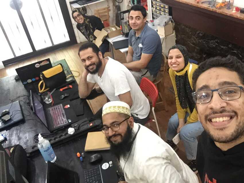
These past 2 weeks were very productive weeks . I have learned a lot from it starting as a group assignment to have a good team spirit till individual tasks to do all the work on time, as all other group members depend on it. After all, I am very lucky to have good friends/colleagues in this academy with me this year whom I consider as my second family.
As for the assignment, we had built the “M.O.A.O Machine” , which is basically juice dispenser machine also known as (inspired by cocktail machine). All the information about this assignment is documented on our group page ( link).
As for my individual tasks: I was assigned to do as follow:
1- Structure design :
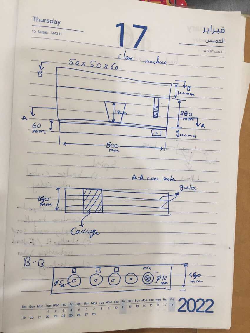
So my work all depended on the first group meeting where we decided the project itself and roughly its shape by sketching it together so that we can all be on the same page and also everyone can design their work accordingly.
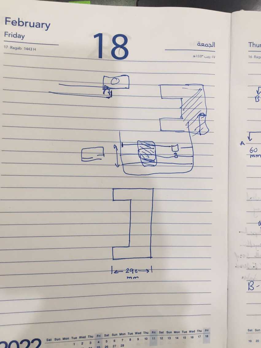
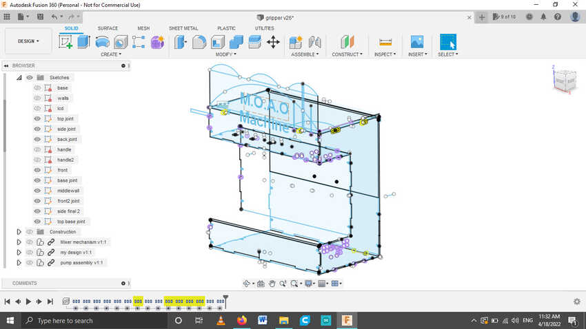
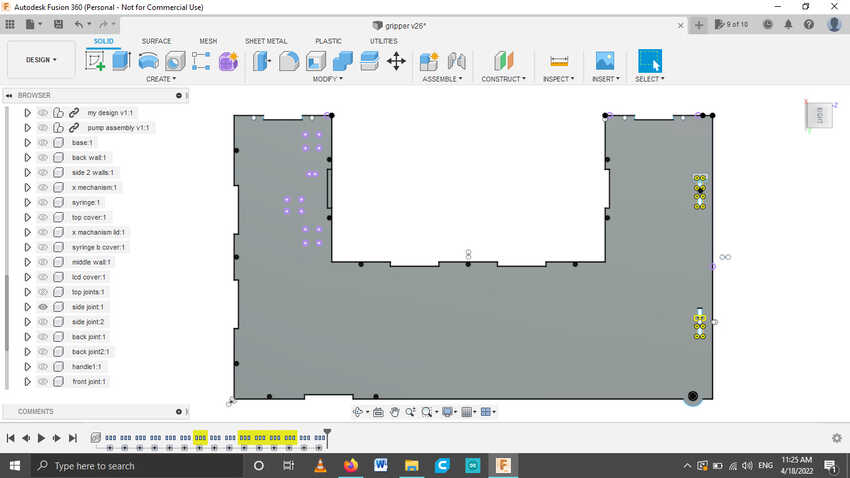
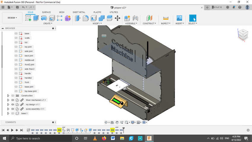
I started designing on Fusion360 by creating a new sketch and drawing a very simple sketch and mastering the extrude tool to roughly draft the full structure without any joints of fittings . It was a unique way to start with but I went with the flow. I was very impressed with my skills to 3d design the whole structure with only 1 simple sketch :
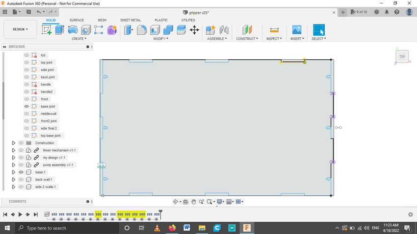
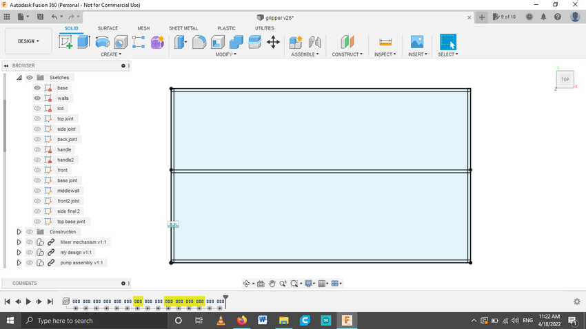
As for the fittings and joints, I decided to create a new sketch for each and every plane/ part and started adding the fittings and joints in it. I used finger press fit with screws/ T slots to make the structure more rigid and capable of holding each other well.
2- integration/ CAD assembly :
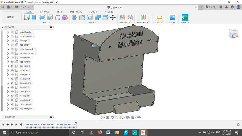
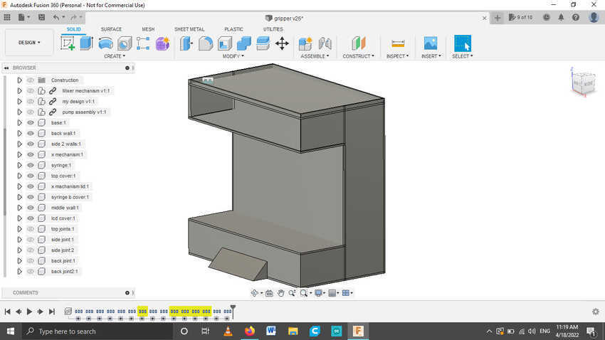
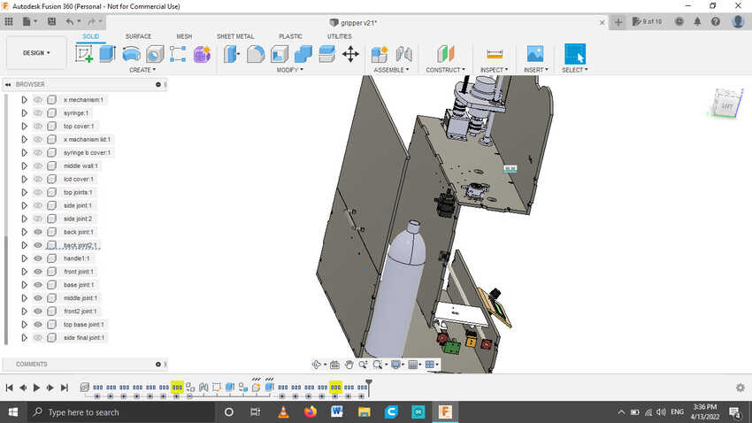
As for the cad assembly I collaborated with each member of the team to upload their design as a step file or fusion360 and integrated it into my fusion360 file. As I added each design in my file I was able to place them well by using the default move tool.
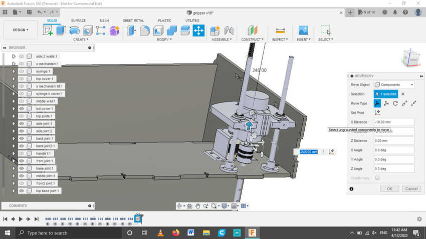
I integrated mixer mechanism and accordingly designed the holes for the screw by using the Project tool.
Then I integrated the X belt mechanism, and accordingly designed the screw holes.
Also integrated the pump mechanism and intigrated with my design.
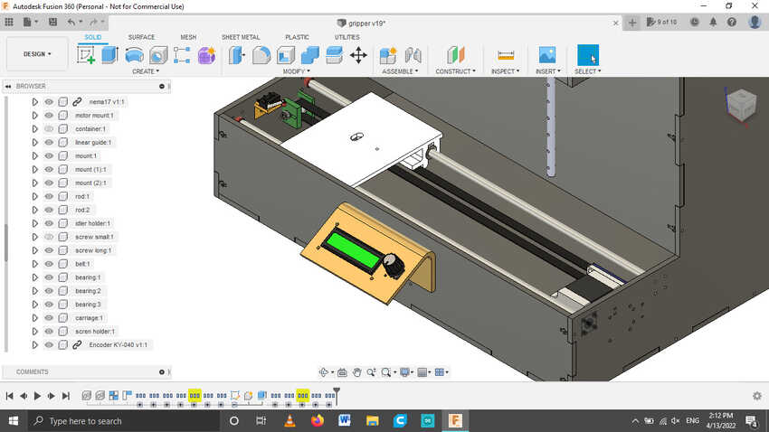
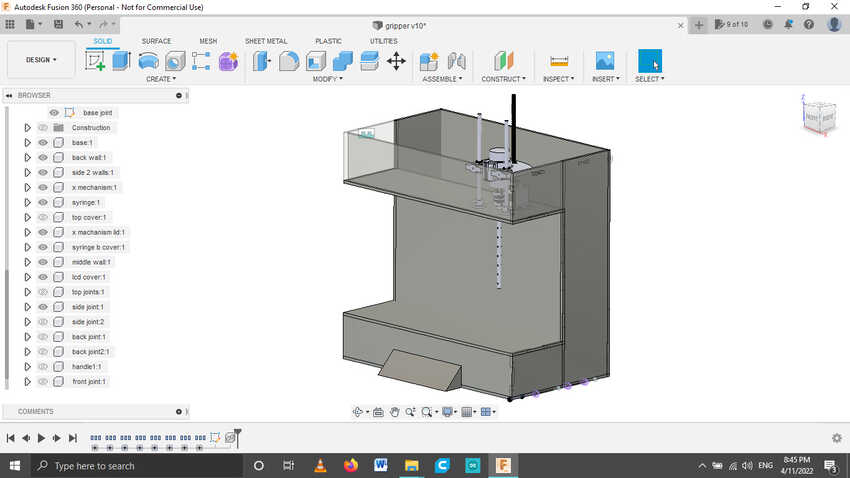
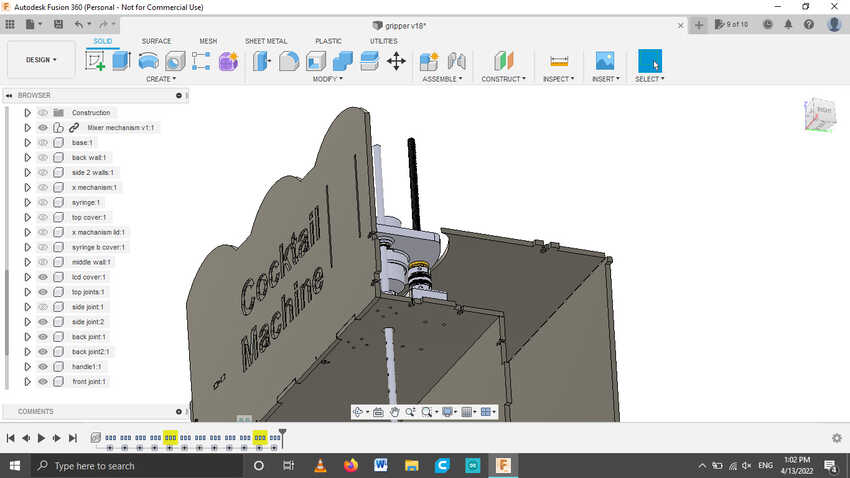
Here is a hero shot after integration.
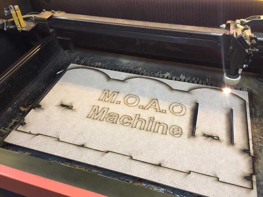
3- fabrication :
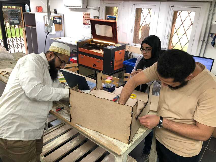
I fabricated the structure on mdf 4.7mm - due to paramtectric design challenge it gave out many errors but we were satisfied due to time constraint, which I grabbed the opportunity to apply feedback on the prototype.
Then I assembled it with the help of my colleagues and completed it so that everyone can use it to test their electronics on the structure.
dxf files + handle stl.
5- structure programming :
I roughly made a flow chart of the final code. So that everybody can calibrate and use the output device accordingly.
The file pdf will be available click here..
6- Code integration :
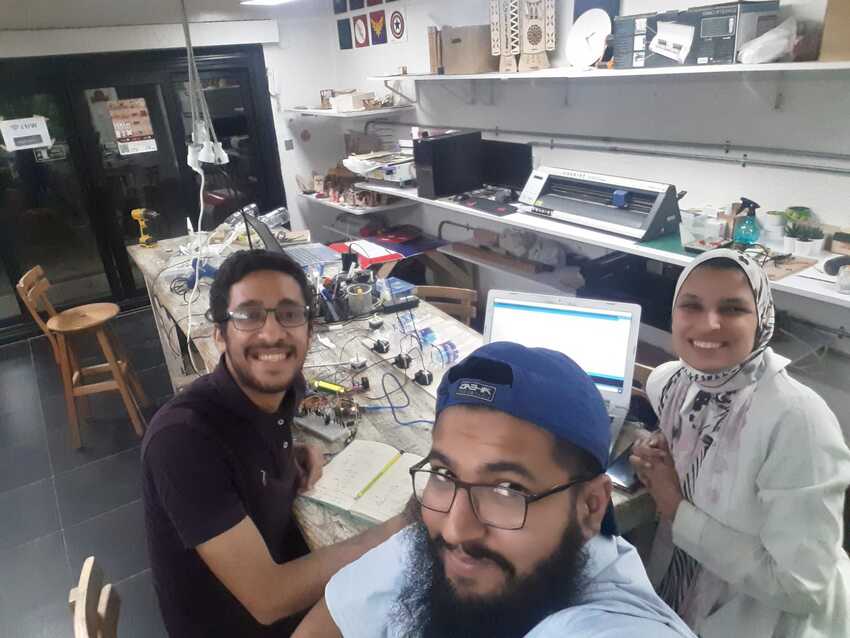
There was an end moment change in the assigned task , code integration was done by all of us together, to speed up the process and to check if all the modules were working or not.
We were using the spiral integration, checking each module individually then connecting all in 1 circuit then re-checking each module individually for confirming working condition. Then final code integrating to achieve our need in the end.
7- Helping others: :
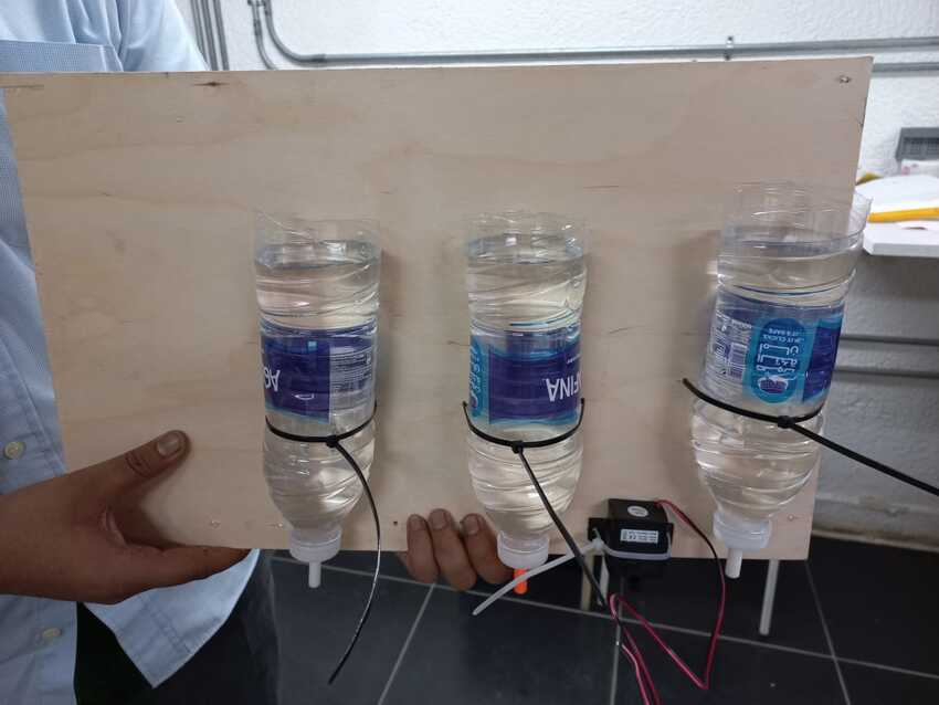
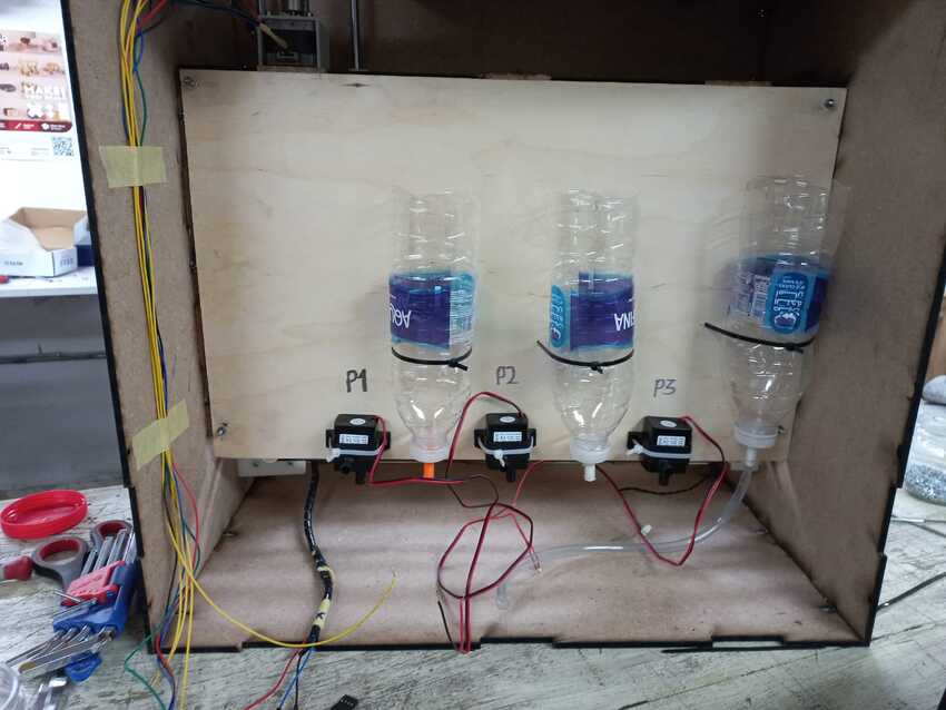
Throughout the assignment we helped each other in every possible way, I also helped them as best I could. Especially when I had to continue in the pump mechanism- try/ check the pump, assemble it in the prototype structure and to make sure quality control is there :) I poured all three bottles with water to check if the plywood sheet will withstand the weight or not.
In the assembly I used zip tie fixation which helped in saving time for fabricating another fixation. Also, I used a plywood 3mm sheet as it is stronger than mdf.
In the assembly process I encountered some differences also, such as as the pump was requisite very late. So we didn't have the chance to accurately print bottle nozzles so with a hot air gun we started melting the tip of the tube so that with flexibility it enters even big sizes.
Here is the final video.
Voila its done
#Challenges 1
parametric design was not correctly designed.
#Solution 1
there were many errors and warnings on fusion360 if i change the main stock thickness parameters or kerf. So I had to basically redo all the design all over again. The main mistake was I was using wrong constraints for a parametric desin, example: for a rectagular slot it is strongly advisable to use the center point rectangle, so that it doesnt effect the placement of the rectangle. Whereas the other due to other constraints the rectangle will shift according to the change.