


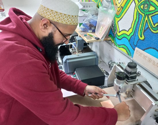
Here is my Hero-shot of the week! Honestly, I am amazed by the fact that in an hour we can design and fabricate and have a working PCB board, surely in those first couple of weeks it will take longer for designing, fabricating, soldering, programming and troubleshooting. But I hope by the end of Fab Academy I could really finish this long process in an hour successfully. I personally used Roland MDX-20 machine this week and here is what I made.
Let's start first with the group assignment
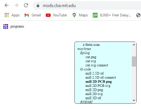
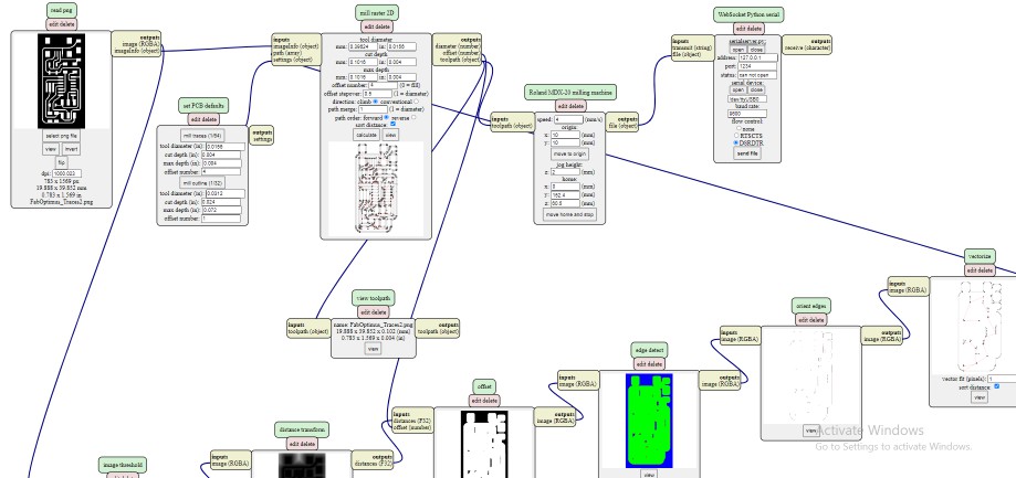
We started with characterizing the machines we have in Fab Lab Egypt, which are Roland MDX-20 and CHINA CNC Zone 3040 Z-DQ. So, we first dowloaded the line test - traces and line test - outline. Then our instructor Kamel divided us into 2 teams, Omar Seif and Omar Senbisy worked on Roland and Moiz and me worked with 3040Z-DQ. So, first thing we used mods to convert the png photos into g-codes. it was my first time dealing with mods so Omar senbisy helped us and sent a guide which made it much easier, I shall attach it with the download files. Also, found a mods in Fab Academy tutorials which always helps me alot to get an idea of brand new things I deal with. After we opened mods, right click > programs > open server program then from machines we choose mill 2D PCB png
This will open a set of windows, it looks hard to understand at first but it gets easier within mintues.
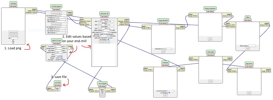
Then after changing the values and clicking "calculate" the tool path appears in another tab and we can now safe the NC file, and we repeated this process again to produce G-code file for the outline png.
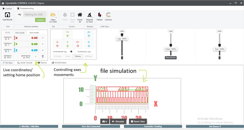
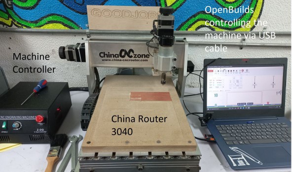
Now that the .NC files are ready we went to the machine and ran the software that controls it which is OpenBuilds, and here is how the GUI looks like.
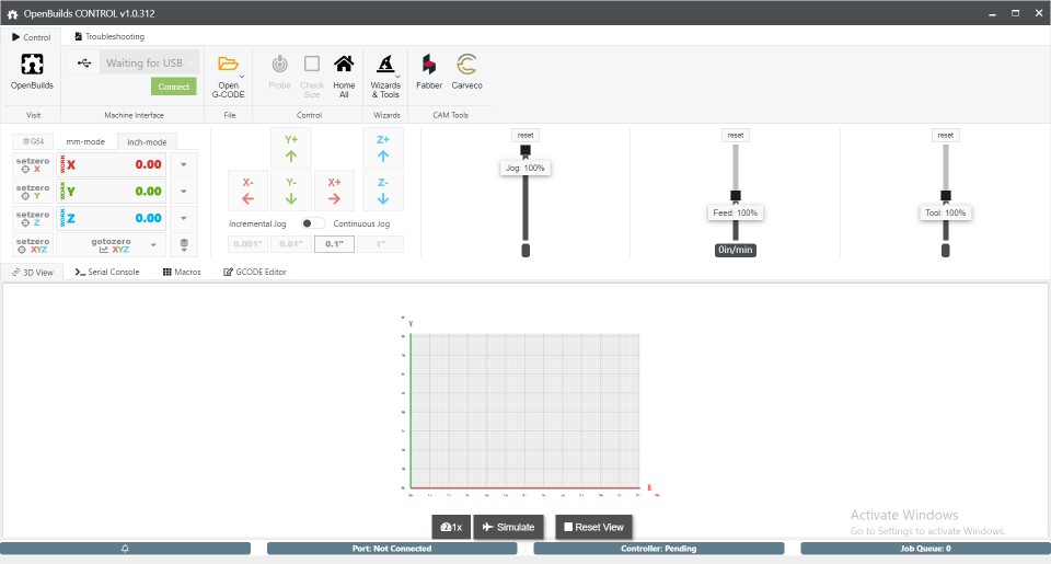
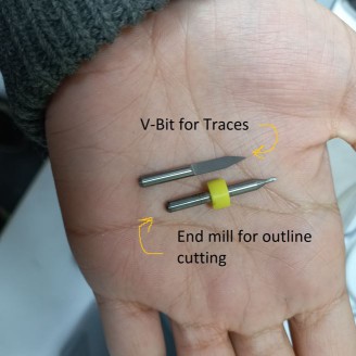
After that we connected the machine's usb cable with Moiz's laptop and connected the software. what's left was to prepare the PCB sheet and hold the v-end mill bit in place so we could start with traces.
Then moiz fixed the V-bit for tracing and we started cutting off copper layer and later worked with End mill to cut the outline.
After we finished, we compared the results and it turns out that Roland MDX-20 is way more precious than China Router as the next image shows.
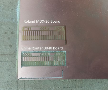
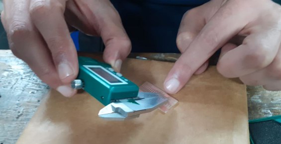
The Modela got to make the thinnest line which after measuring with the caliper was around 0.25mm but unfortunately the other machine started to make lines with width 0.4mm, after those results we all agreed to use Roland MDX-20 on our individual assignments xD
 And now, The assignment!
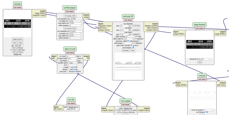
I used FabISP programmer using ATtiny44 in Ali's board. I can't describe how much I learned from his documentation and the useful resources he recommended. We almost repeated the same tool chain we walked through in the group assignment. which is Mods > fabrication on Modela MDX-20 > then soldering > finally programming. In Mods I followed those steps: open Mods > right click then choose program > open server program > Machines > Roland MDX-20 > PCB png. After that I uploaded the traces png and changed some parameters, clicked calculate to generate tool path.
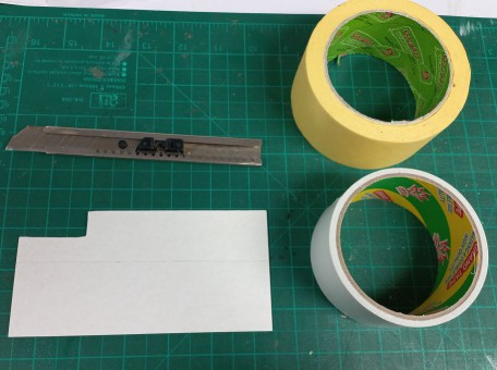
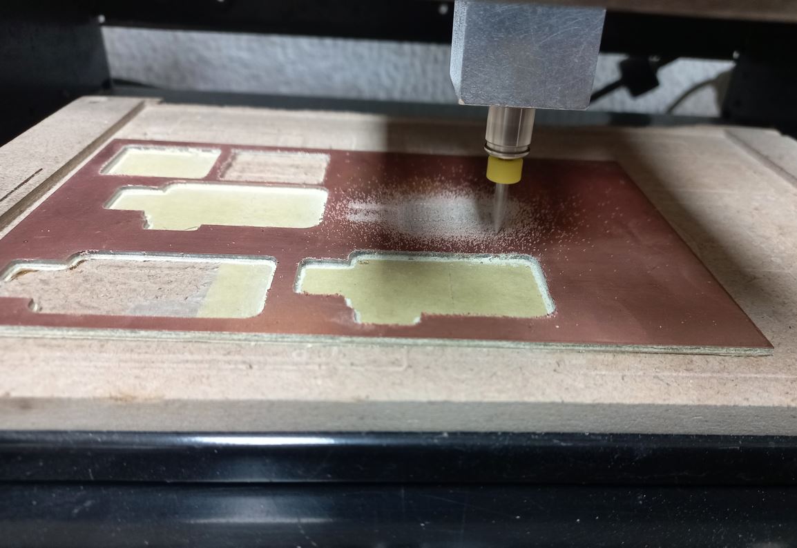
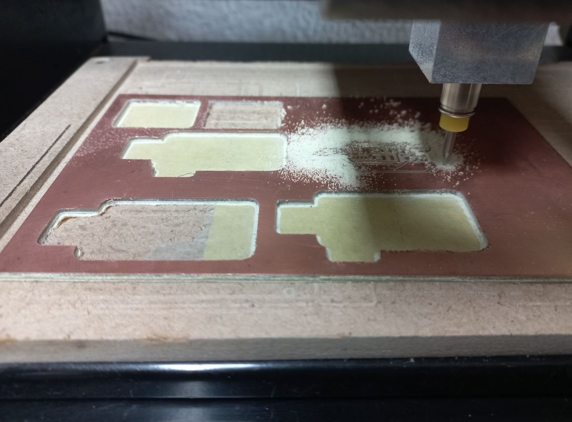
I used the same V-bit and End mill I mentioned earlier in the group assignment, so first fixed the 0.4mm V-Bit and prepared the PCB board using tape and double face on its back to fix it well to the Machines bed.
Now that everything is ready, back to mods > from Websocket Python serial hit "send file".
Then repeated those last steps for outline png and manually changed the V-Bit to use the 1.15mm end mill, used the original png as it is because there was around 1.5mm between the outline and traces which was enough space inside to fit the end mill to cut through without touching any traces.
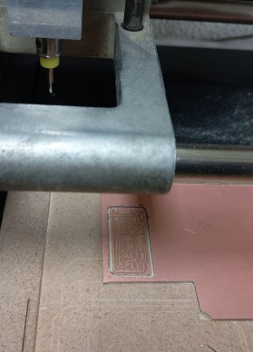
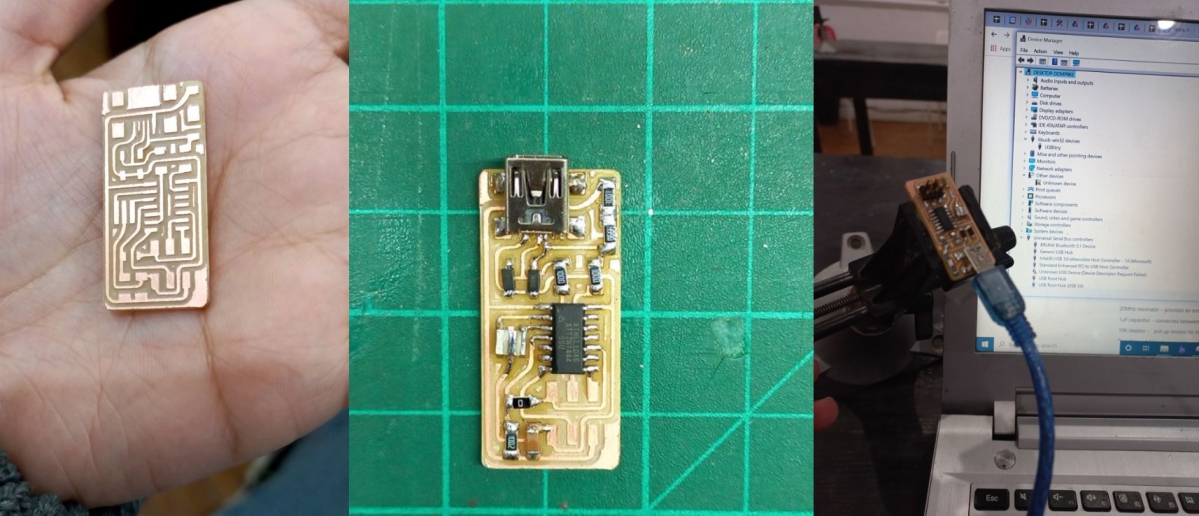
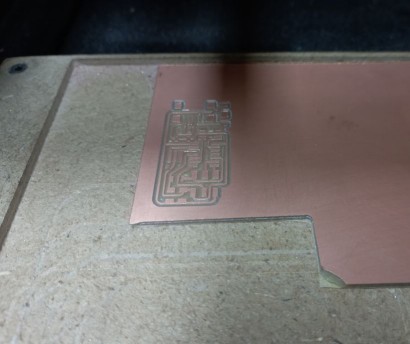
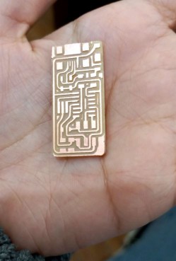
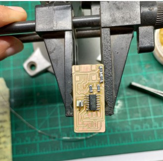
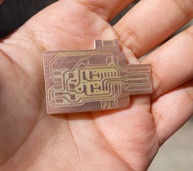
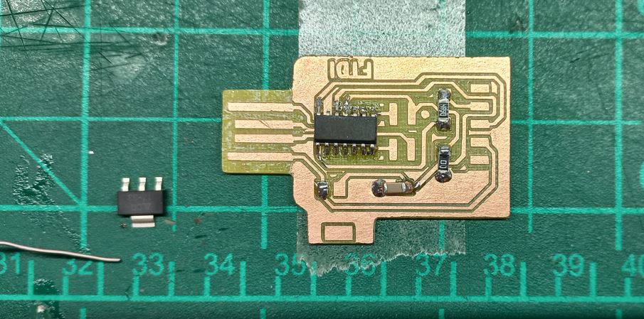
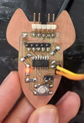
Aaannnndd Done! It looks great to me.
Now that the machining is over means we need to solder!
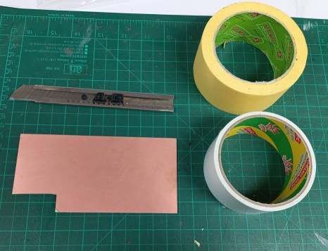
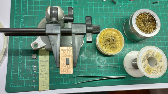
I consider myself rookie in soldering as I learned it very recently for Fab Academy. Through my work in Fab Lab Egypt I worked on projects that needed soldering but it wasn't frequent, and all of them were using through-hole components So I am not yet used to these tiny SMD components :D But with the help of Duaa session in the bootcamp about soldering I took notes that helped me alot and of course Neil's steps in this week's lecture. So first I collected all of the circuit components next to me and also all the tools needed in the soldering operation which are: soldering iron, solder, flux, clamp, twizzer, and wire-type soldering iron tip cleaner. So, here is the setup that was in front of me.
Then I started soldering from the center to edges.
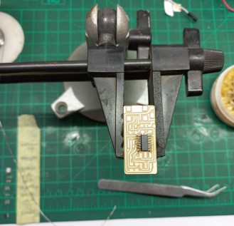
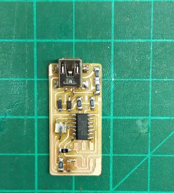
While soldering I did mess once while soldering the micro-usb component as they are tthe tinnest traces in the board, I made a short between 2 pins so using Desoldering weck it finally was okay. After I was done I used the Avometer in the buzzer mode tocheck if there were any short circuits I didn't notice but it was all well. It was now finished, all shiny and a bit neat. I was happy with it, there was only the isp 6-pin headers missing but the next day I soldered them before programming.
Finally, Programming the board!
I followed 2 tutorials to complete programming the board successfully which were: Fab Academy week4 Fab ISP tutorial -love them- and windows 10 toolchain to setup the required AVR environment. you can find it here.
I already had Git-Bash, so I installed Atmel GNU toolchain, GNU Make, avrdude and of course the firmware. They seem much but it was a straight forward process. So here is the folder I put on everthing looked like.
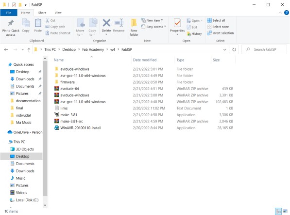
Finally opened Git Bash terminal from the firmware folder to have the correct path - Thanks to Moiz and Omar Seif tip for that - and ran the next lines: make clean > make hex
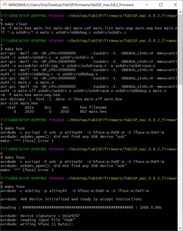
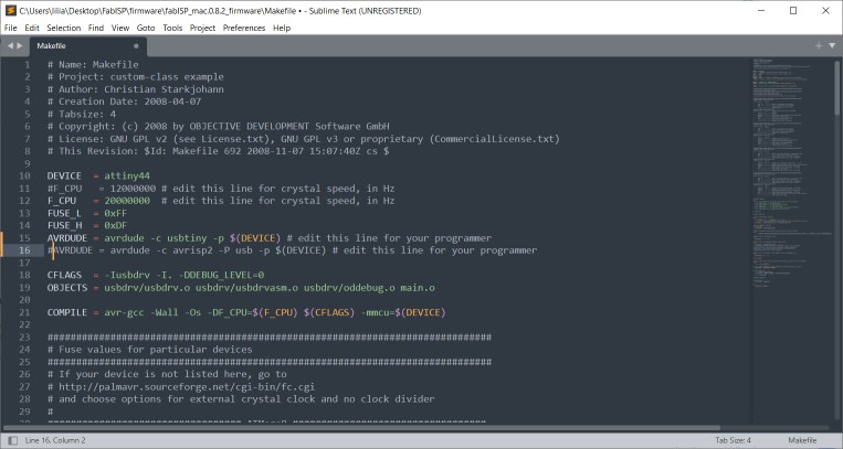
To program by board I used Moiz's FabISP - Thanks Moiz - So I had to edit the Makefile to change the programmer from avrisp to usbtiny
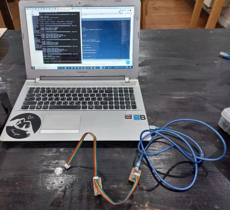
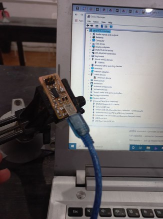
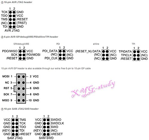
Then connected FabISP to my laptop through micro-usb cable and connected my board with the fabISP through the 6-pin ISP protocol which are: MOSI, MISO, VCC, GND, SCK, and RESET. the connection is as follows in the next image.
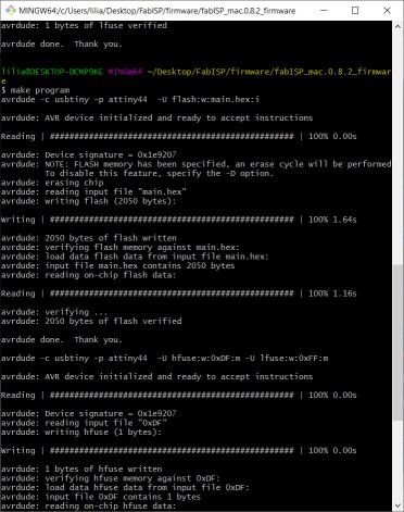
Then continued in Git Bash the last 2 commands which are: make fuse, make program. And DONE!
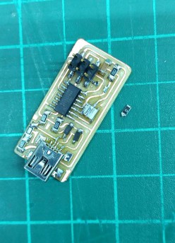
Then to test it I needed to connect it with my laptop but first I needed to remove the 0 ohms resistor and cut the VCC trace from the 6-pin ISP as Ali recommended
Then came the moment I worked 2 or 3 days to reach! I connected my board with my laptop! It would have been very exciting if it worked right away but projects tend to not work at the very first time :D the laptop didn't detect at all anything through different usb ports. I didn't know what was the issue, So Moiz suggested that I recheck on the soldering or just reflow some connections as if one was a cold joint it may not connect well. And so I did! and then tried again connecting the board to the laptop through usb and IT WORKED!
I opened the device manager, The windows detected it but it had a yellow triangle next to it which meant it needs a driver So I searched online and found "adafruit_drivers_2.5.0.0" and once I installed it, it was recognised as a USBtiny.
 UPDI Programmer
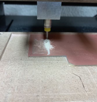
Did you think that was it! Nope! There is another programmer to be made which is a UPDI programmer, where we are able to program a board by only two pins which are UPDI and GND not like SPI with 6 pins like I described earlier. First of all the design was available through this link but we didnlt have the same coltage regulator in our inverntory so our instructor Kamel edited the design with the one available and gave us the gerber files and we started from there. Then I did the same as I did with the USBtiny programer, extracted the PNG images and then started milling it on Modela. Here are images of this step.
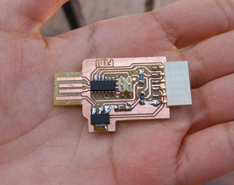
After finishing it it was beautifully done. I was happy with the perfect Z-depth that I made the V-bit milling off the copper layer. Then started soldering components from center out and from low height to higher. Also I used Omar Seif's technique of fixing the board by a double face so it wouldn't move - Thanks Omar - soldering didn't take as long as the first programmer, skills do get better after practicing each time :D
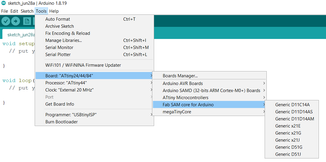
Next step was programming the board. following the same link of the board's design was instruction of setting up the programming environment which led me to the firmware that I had to intsall in Arduino IDEm named Arduino Core for Fab Sam, which was made by the awesome Quentin Bolsee.
and added the URL "https://raw.githubusercontent.com/qbolsee/ArduinoCore-fab-sam/master/json/package_Fab_SAM_index.json" to Additional Boards Manager URLs" in the Arduino IDE > File > preferences. Then from the boards manager I installed the Fab SAM core and yaay it was installed and then I could choose D11C14A which was the MCU we used.
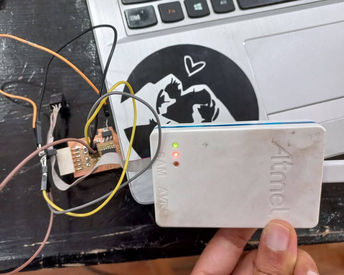
Next was to burn the bootloader on the board, so I connected it with the Atmel-ICE through 10-pin SWD connection in the next image. Then from Arduino IDE, Tools> Burn bootloader. CAUTION: The MCU is only supplied by 3.3V not 5V so we soldered a wire on the regulator to supplu the VCC for the board.
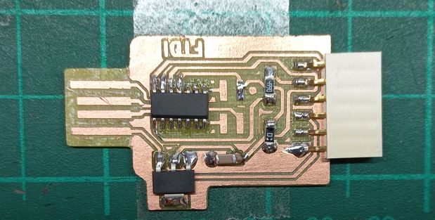
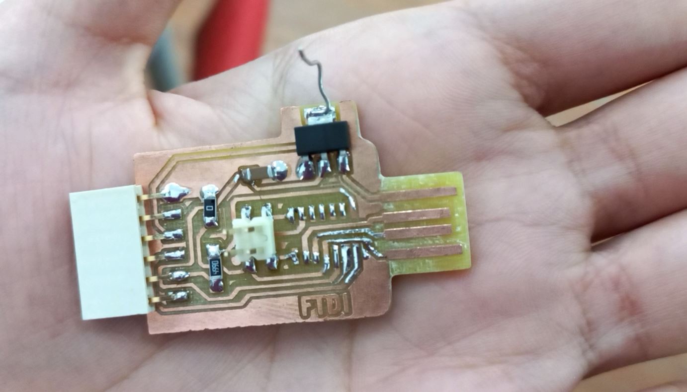
After burning the bootloader we no longer need ATmel-ICE and we can directly connect the board with the laptop as it has a USB connection. But here is were I got stuck for weeks. The board wasn't reconised by the laptop when I connected it alone, it doexn't sense anything at all, But when it's connected with the ATmel-ICE the laptop read it. When I told Kamel that he told me that there must be an issue in the USB connection lines which were 4. We looked carefully at the board but nothing looked wrong at all. so we used the AVO meter to buzz each of the 4 lines to see whether it's connected to the MCU and here we found that the GND line wasn't connected. This tricky line wasn't connected at a tiny place under the MCU that's why we couldn't see it! so kamel helped me to de-solder D11C and remove it from the board and then we wired the GND line and soldered again D11C. here is a picture I took after we soldered that @&%&%# line.
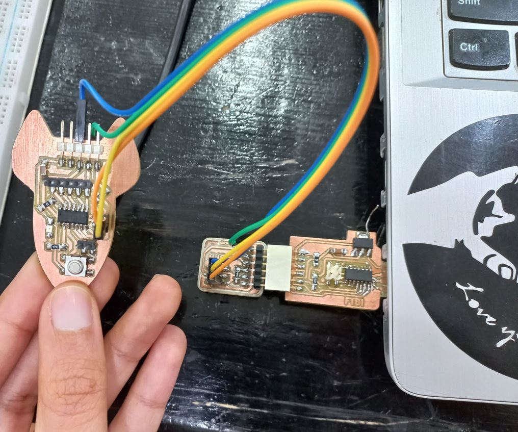
Then I tried to connect it alone with my laptop and YAAAY the laptop recognised it! what was left was the final step which was trying it as a programmer. so I tried it with my ATtiny1614 board. So first i needed to install the proper core for it. so added "http://drazzy.com/package_drazzy.com_index.json" also in prefrences and from boards manager installed megaTinyCore by Spence Konde. and finally connected the programer with ATTiny1614 board and tried a simple Arduino blink code and it worked!
 Source files:
UPDI programer -different voltage regulator footprint
Source files:
UPDI programer -different voltage regulator footprint