


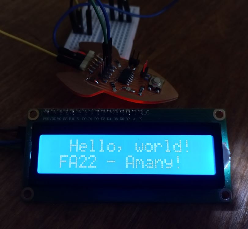
I also used different microcontrollers while doing so, which are ATtiny44 and ATtiny1614. Here is my Hero-shot of the week!
 Let's start first with the group assignment
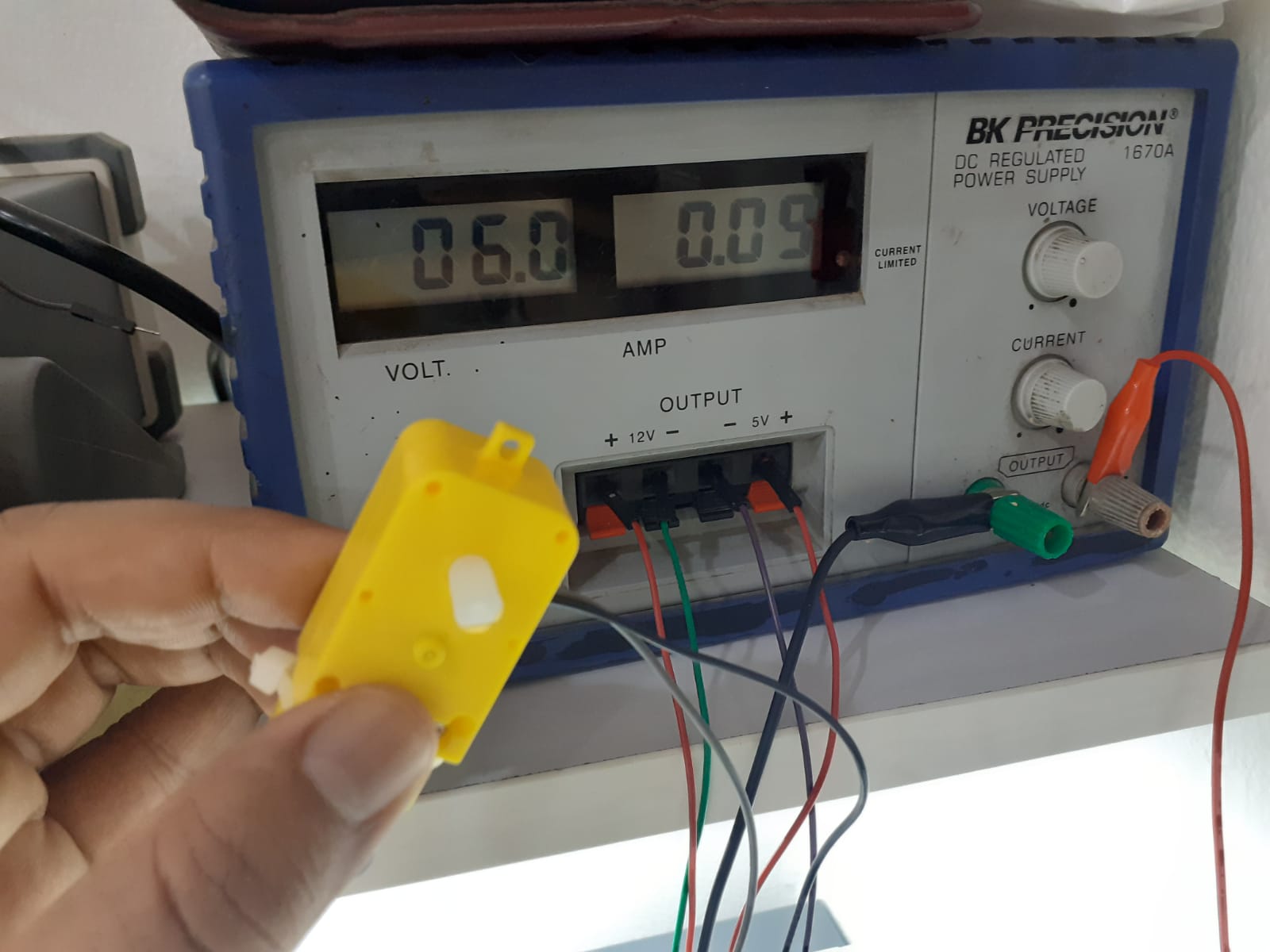
We wanted to measure the power consumption of an output device, we tested a geared DC motor. We first tried the power supply whiched showed it consumed 6 volt and 0.09 Ampere which is 90 mA. power is calculated by multiplying volt and current through the next equation: P=V*I, here is a good tutorial explaining the equation so the motor consumes P = 6*90=540 mW "milliwatts"
We also tried measuring current and voltage using AVOmeter. Here is a great tutorial from Sparkfun of how we use AVOmeters. In short, voltage is measured as we put probes in parallel connection with the component we want to measure voltage on. But current is measured in series connection, so we must cut the circuit and put the probes in between components we want to measure.
The AVOmeter was more accurat as it measured the current to be 85mA not 90mA
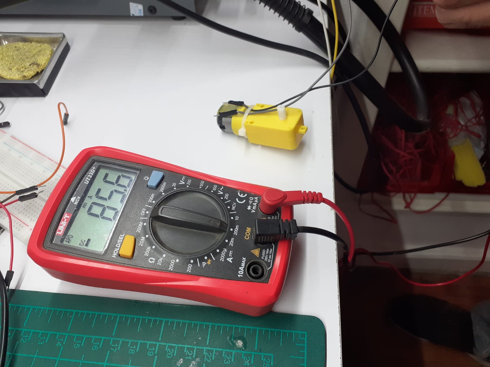
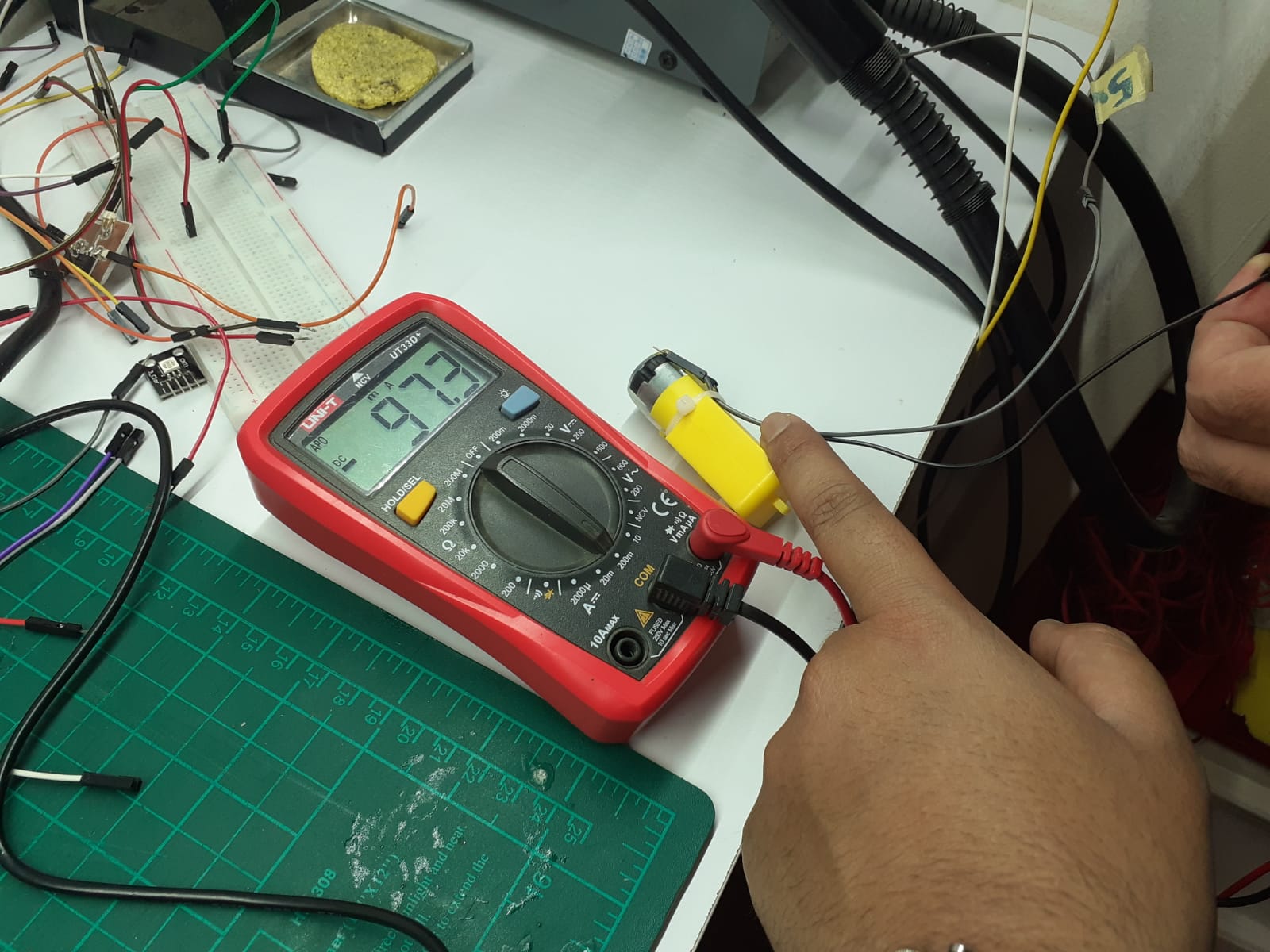
85mA was in No-Load mode, But as we put a load on the motor "basically hold its shaft with our hands" it consumed more power so the ampere went up from 85mA to around 100mA
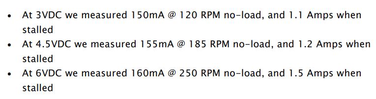
Basically we can find all the data we need in the datasheet of the component we will use, So here is geared DC motor datasheet from adafruit which shows that at 6V the motor should consume 160mA and up to 1.5A while overload. Although what we measured was a bit different but datasheets knows better xD and it's always safer to go with larger power values to consider in PCB design as we will see in my individual assignment shortly.
 Now, The assignment!
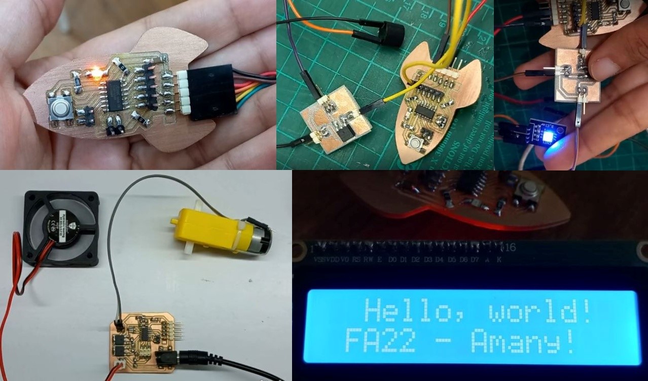
It was a busy week as I worked with LED, buzzer, DC motor, fan and LCD controlling them through ATtiny1614. Also made a board controlling fan and DC motor which I will need in my final project.
ATtiny 1614I used the board I made back in embedded programing week which had ATtiny1614 as its microcontroller. What made this possible was that I connected pin headers to ATtiny1614's GPIO pins.
 LED
LED
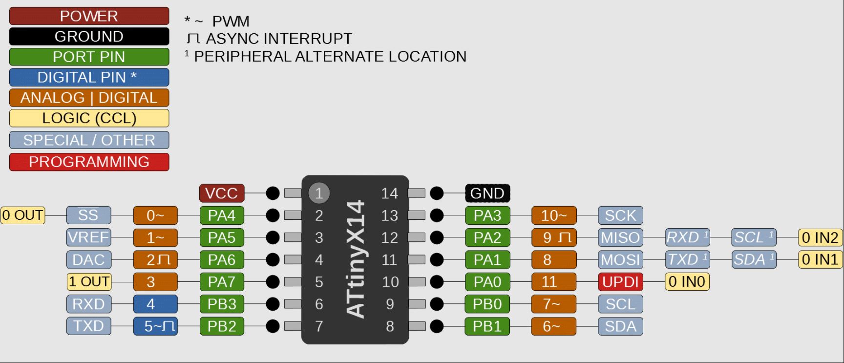
I started with a simple fading code from Arduino IDE examples as the board had a LED and a button already. To make a LED fade we need a pin that can manipulate pulses which is called PWM or Pulse Width Modulation you can know more about how it works from this tutorial. Anyways, from the ATtiny1614 I searched for pins that has PWM and found them from the following picture
I had the LED connected to pin PA4 which in Arduino code is 0 so I edited the code with the pin I am using and upload it to the board.
So here is the final code
          int led = 0;           // the PWM pin the LED is attached to
          int brightness = 0;    // how bright the LED is
          int fadeAmount = 5;    // how many points to fade the LED by

          // the setup routine runs once when you press reset:
          void setup() {
            // declare pin 9 to be an output:
            pinMode(led, OUTPUT);
          }

          // the loop routine runs over and over again forever:
          void loop() {
            // set the brightness of pin 9:
            analogWrite(led, brightness);

            // change the brightness for next time through the loop:
            brightness = brightness + fadeAmount;

            // reverse the direction of the fading at the ends of the fade:
            if (brightness <= 0 || brightness >= 255) {
              fadeAmount = -fadeAmount;
            }
            // wait for 30 milliseconds to see the dimming effect
            delay(30);
          }
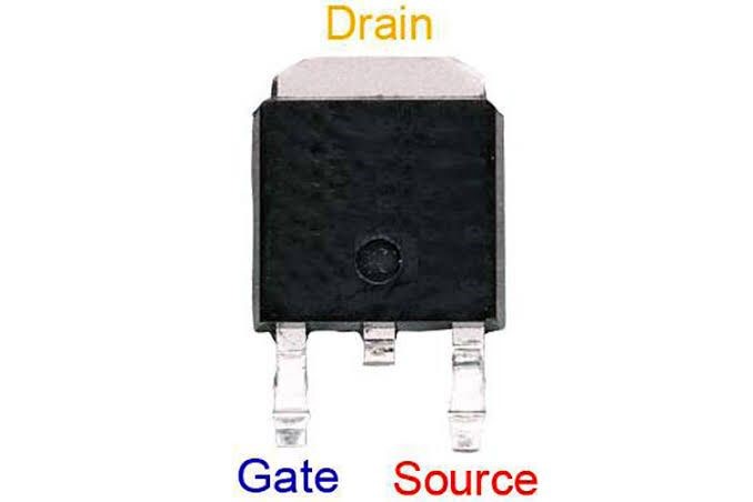
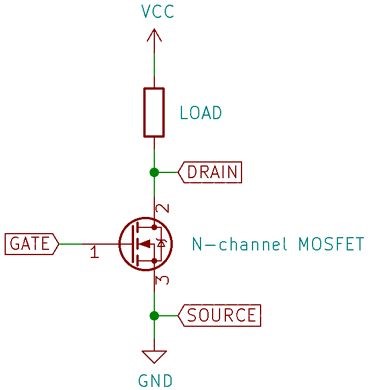
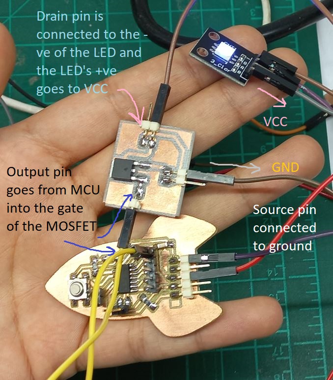
Almost all the following output components used the same code. The main subject was not to consume high amps from our microcontroller, so to be able to run motors or any component that needs high power we needed a component that just recieves the signal from the microcontroller and then runs the high power/voltage circuit, which is the same concept of a switch or relay or in our case we used MOSFET which really acts like a switch as when it gets a signal in its gate it connects between the source and the drane, closing the circuit and running the output component
 LED
LED
So connected the led the same way I just described and yaay!
 Buzzer
with the same code and connection changed the LED pins with the Buzzer and listened happily to its ugly sound :D
MotorAlso, with the same code and connection changed the buzzer pins with the Motor's
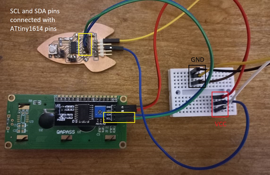
LCDRunning the LCD with a bit different as it used I2C communication which is mainly using 2-pins SCL, and SDA with the MCU we are using, so back to the ATtiny1614 pinout I found PB0 and PB1 are the ones I am looking for which are pins 6 and 7 in Arduino core so changed the code and TaaDaa!
          //Compatible with the Arduino IDE 1.0
          //Library version:1.1
          #include <Wire.h>
          #include <LiquidCrystal_I2C.h>
          LiquidCrystal_I2C lcd(0x27, 20, 4); //
          void setup()
          {
            lcd.init();    // initialize the lcd
            lcd.init();
            // Print a message to the LCD.
            lcd.backlight();
            lcd.setCursor(2, 0);
            lcd.print("Hello, world!");
            lcd.setCursor(1, 1);
            lcd.print("FA22 - Amany!");


          }
          void loop()
          {
          }
 Fan and Motor board
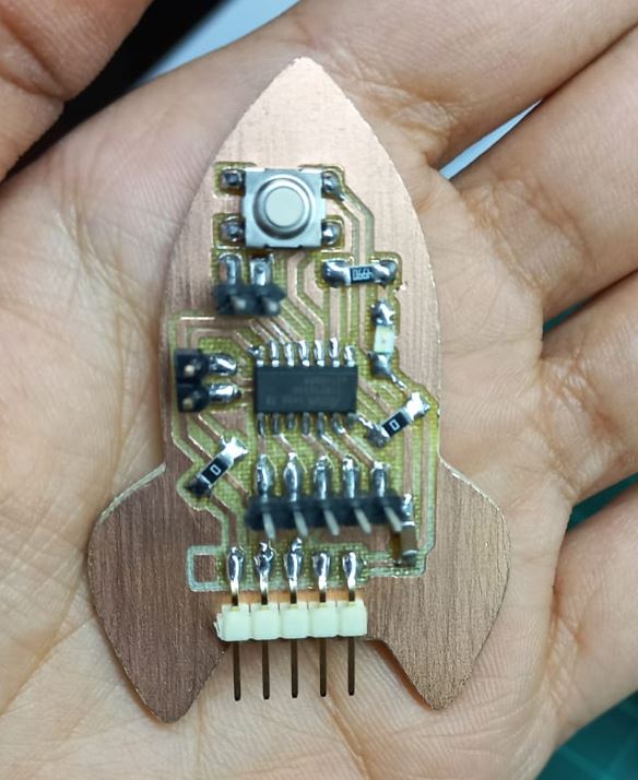
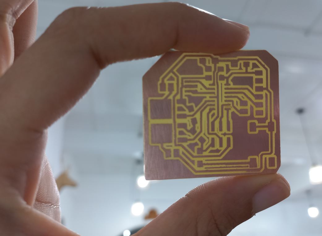
Finally I made a board that controls a fan and a motor as I will need them as outputs in my final project. The MCU I used was ATtiny44 but really nothing has changed as I also used MOSFETs to control the circuit. I could have used H-bridge IC but I didn't need to switch motor directions. I am a bit happy that I am now easily integrating between more than week in 1 board as I designed it then did its production then programed it to control an output device! 4 weeks in 1, honstly It's something I couldn't imagine to make in only 4 hrs!
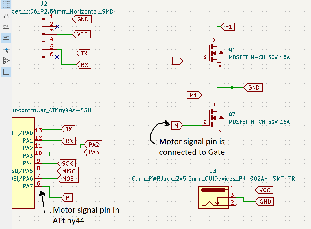
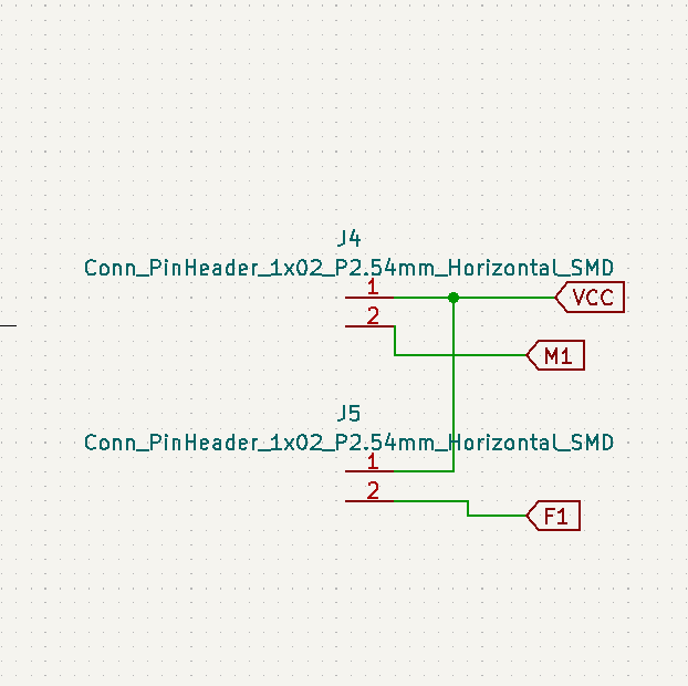
I designed it in kicad, the schematic main connections were the same as Echo Hello board in the PCB Design week just added 2 MOSFETs connected to ATtiny44 GPIO pins and DC power jack for connecting the adaptor and 2-pin connectors to easily connect the fan and the motor.
The full connection was as follows:
- MCU: output pin is connected to MOSFET gate
- MOSFET:
- Gate: connected to MCU to get the signal.
- Drain: connected to 1 terminal of the Motor/fan.
- Source: Connected to GND.
- Motor/Fan:
- Terminal1: connected to MOSFET drain
- Terminal2: connected to VCC
So as we can see the Motor 2 terminal are not connected directly to VCC and GND so it will run only if the MOSFET closes the circuit between its drain and source which at then will connect the load with VCC and GND.
after a bit playing around with the footprints and airwires of the board it was done
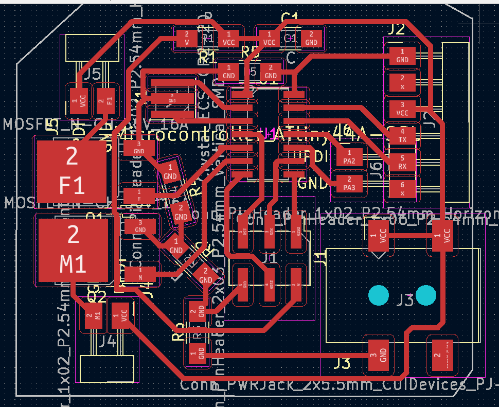
Then did the fabrication in around 30 mins and then soldering in about 45 mins :D
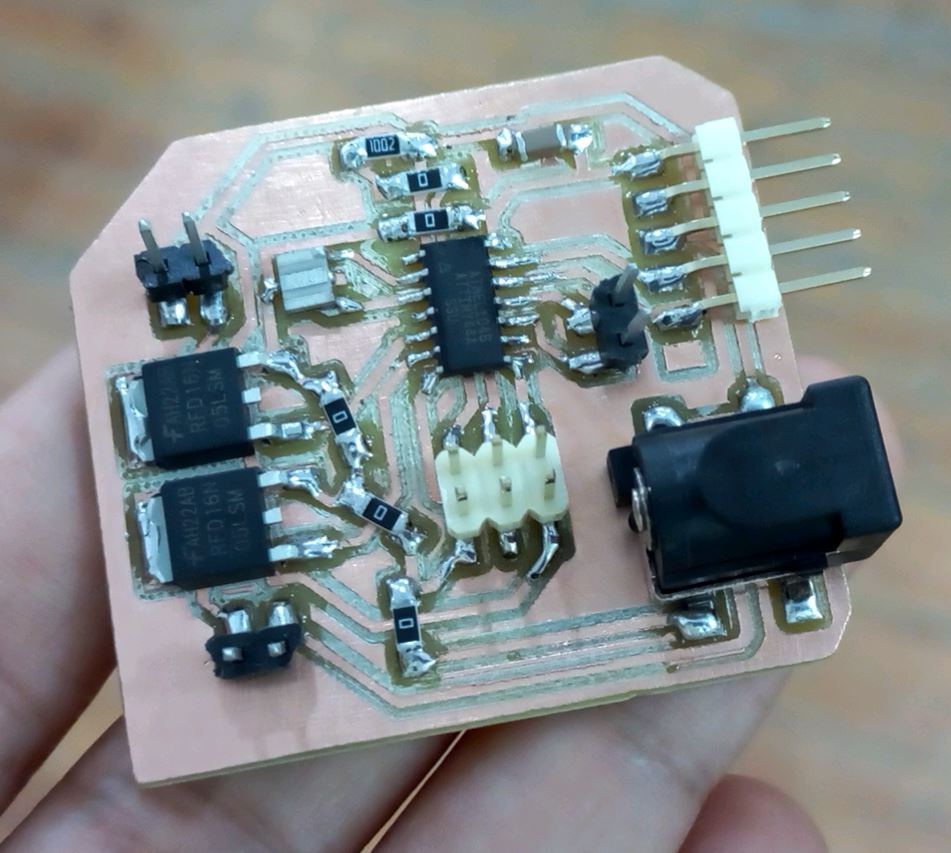
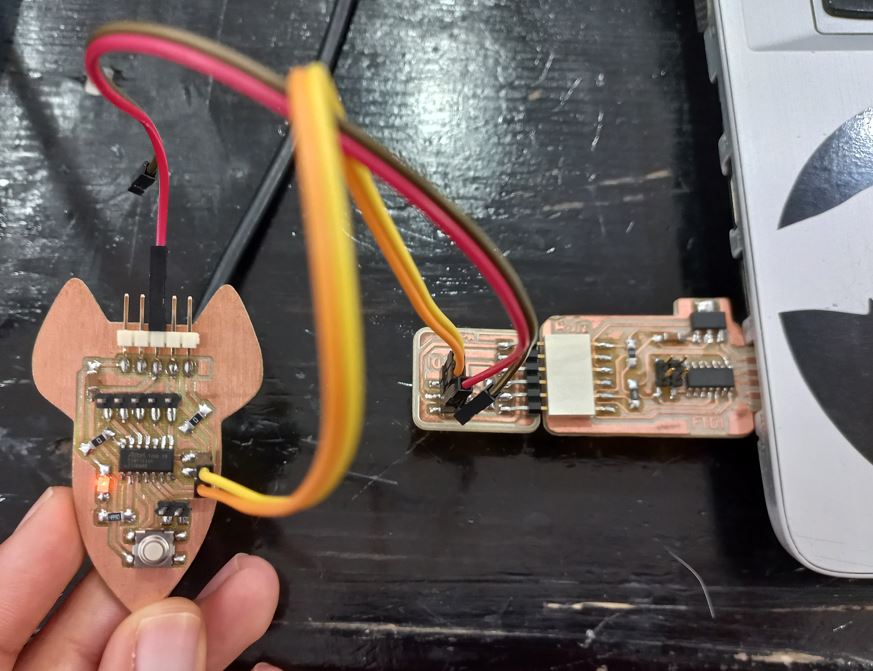
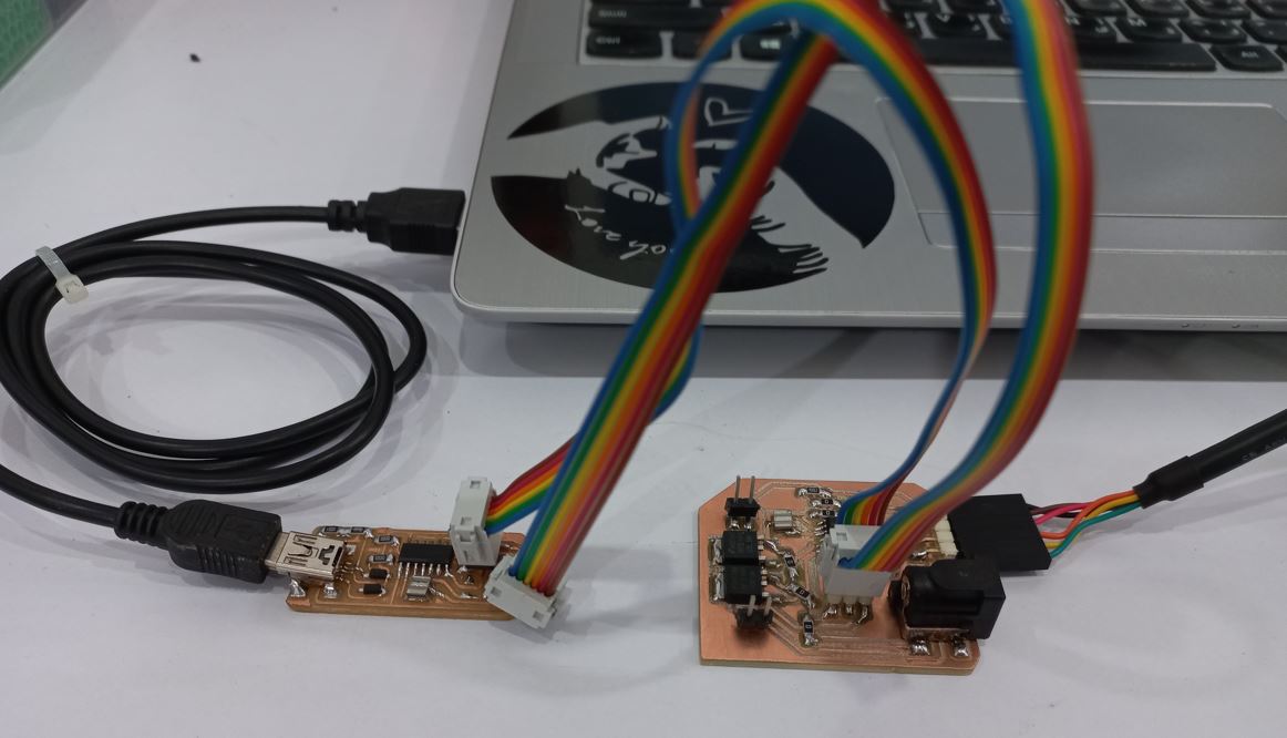
Then used FabISP to program it, the code was as simple as turning them on and off, I just needed to make sure that both are working in the same time with no problems. Here is the code I used:
            int Motor = 7;
            int Fan = 8;
            void setup() {
              // initialize digital pin LED_BUILTIN as an output.
              pinMode(Motor, OUTPUT);
              pinMode(Fan, OUTPUT);

              CLKPR = (1 << CLKPCE);
              CLKPR = (0 << CLKPS3) | (0 << CLKPS2) | (0 << CLKPS1) | (0 << CLKPS0);
            }

            // the loop function runs over and over again forever
            void loop() {
              digitalWrite(Motor, HIGH);   // turn the Motor and Fan ON
              digitalWrite(Fan, HIGH);
              delay(2000);                       // wait for 2 second
              digitalWrite(Motor, LOW);    // turn the Motor and Fan OFF
              digitalWrite(Fan, LOW);
              delay(2000);                       // wait for 2 second
            }
 Source files:
Individual Assignment files
kicad design