


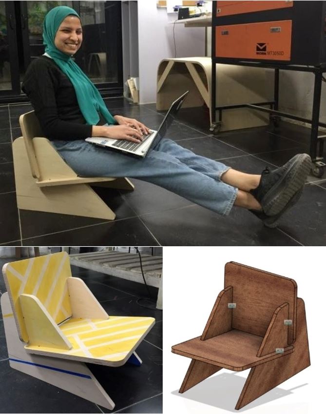
Here is my Hero-shot of the week! I was so excited about this week as there are limitless ideas for Furniture that I like. So I said to myself that I will just make a "hello world" sample to get to know the toolchain of designing, generating G-Code, machining, post processing and assembly, Then for sure will make lots and lots of designs later. I fell in love with the idea of designing something customised for just Amany and what would I like my furniture to be.
Let's start first with the group assignment
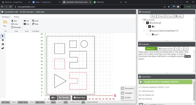
We wanted to charactrize the machine and calculate the Runout value + walk through the toolchain. We don't have a CNC Router in our lab so we worked with 40*30 cm CNC Milling machine, but it was the same concept just scaled down to 1:5 of the real router machine :D. so we used a simple 2D design of rectangles and squares. For generating G-code we used OpenBuilds CAM website so we added the file then set the settings, as follows.
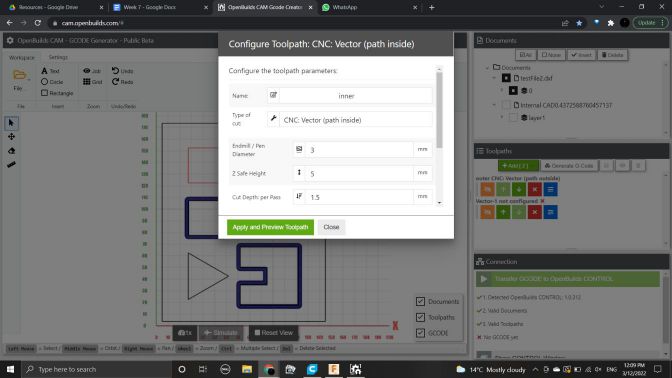
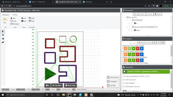
We set each of them with different settings, like the tool to be outside or inside or inline. Also, working with this machine, the RPM was liited so went a bit slow for the feedrate and tiny steps in the cut depth in each path which is recommended to equal half the diameter of the end mill we will be using. Then after we were done it appeared like the following picture.
Then we were ready to use the machine now, t be able to control it we use OpenBuilds controller, from it we open the g-code and set the origin point in the 3-axis then run the file.
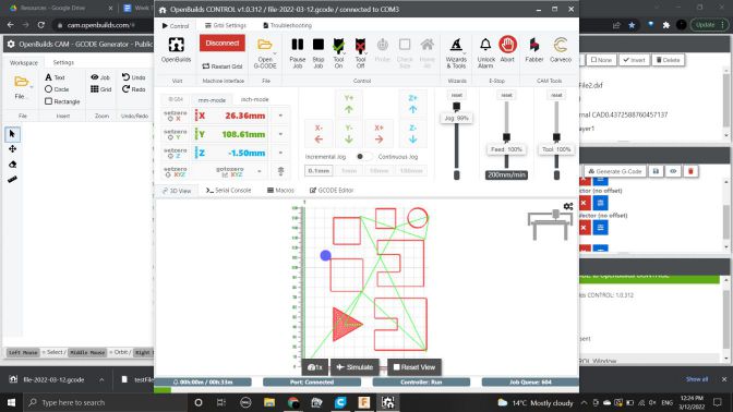
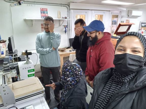
We used 5mm MDF wooden sheet, so we didn't need to fix it with the bed with needles like the large machine, we just put double face on the whole area of its back then fixed it to the bed and started cutting, Here we all were working on the machine
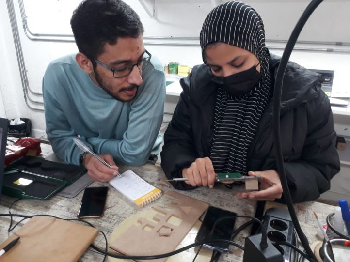
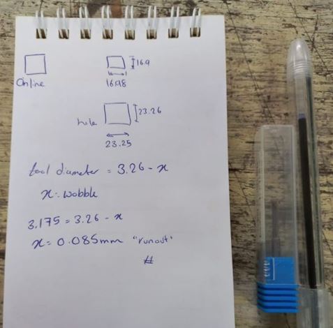
After the file was done,me and Omar Senbisy strated measuring with the caliper the output piece and the sheet itself, So we could find the value of the runout. so from the square we maid the endmill to go through using "inline" mode made us calculate the runout easily as we already know the tool diameter so any bigger value then it will be the runout
We finally found the runout to be 0.085mm, so in our own designs we need to consider making a parameter of the runout value and change it after testing the machine just like we maid as a group.
Now, The assignment!
As always I went to my go-to place forinspiration which is Pinterest. I found tons of interesting ideas. Didn't know which to choose whether it be a table, a chair, bookshelf, coat stand.. etc. So I thought about customising it for me and just me :D I always have the problem that I sit in the squatting position, which hurt my knees alot if I sat infront of my laptop for too long. So I found a simmple minimal design which height seemed not to high, so acuatlly I can expand my legs and sit it on the floor while sitting down, So as a starter it sounded like a good idea. here is the image that inspired me
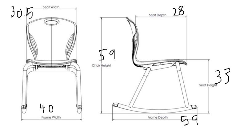
Once I opened Fusion 360 to start desiging I was intimidated by its empty environment! I had now idea what dimensions to set the chair to. So I searched for exsiting chairs in the market to refrence the dimensions to, like the seat width or the back's height..etc. So just typed the values on the picture itself with paint softwar, It looked like this :"D
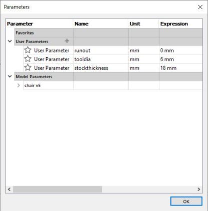
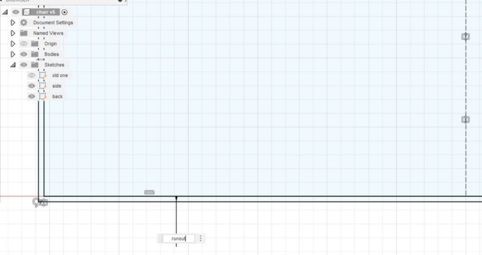
The design itself was easy though as it consisted of 4 parts, 3 of them are the same. so started with making parameters I will use while sketching which are Stock thickness, End mill diameter, and Runout
Then started sketching the side as I felt it's the important part joining the back and the seat, mainly used through connections and made it's width the stockness of the sheet we will be using.
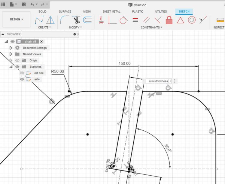
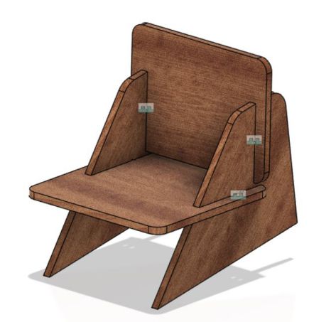
then drawn the back and the seat which mainly started with a simple rectangle then added the through connection as well. and after extruding it appeared like this
Just an important note, I added the run out parameter as an offest of the whole shape, as if there is misalignment in the z-axis the tool may wobble a bit not making a perfect circle making its own diameter, so it will make 8mm even if the tool diameter was 7mm for example. So it will eat 1mm more than it should in the whole design. To compensate that value we can make an offest after finishing the sketch and the offest value could be the calculated runout after characterizing the machine.
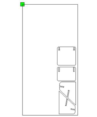
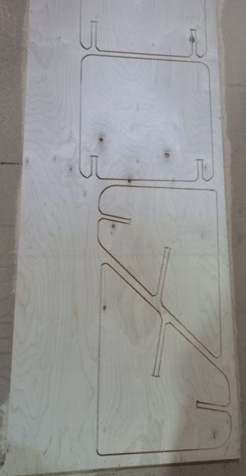
Now that the design was done, I exported the DXFs after making some chamfers for easier assembly. Then, nested the 4 parts inside the sheet we were going to use which was 120*240cm. I had only half a sheet actually as it was divided between me and Omar Seif. it only took 1.5 meters with 0.4 meter width which was around 1 quarter of the sheet we will be using, and as the each one has a limited time on the machine I thought it was perfect and won't take long machining time.
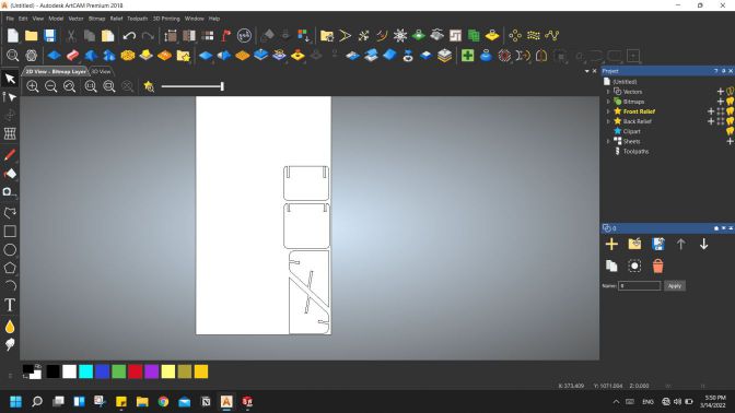
After that, It was time to generate a toolpath. We contacted the workshop that will host us while maching to collect more data about the tool diameter and the extention of the toolpath file, they said it was "Mach2" and ".gcode" file and they used Autodesk ArtCAM software to generate gcodes and worked just fine with them. so to stay safe we also used the same software.
It seemed like an easy software so I opened the DXF files I exported from fusion then started making the toolpath, remember to click 2d view for easier interface.
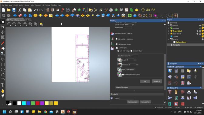
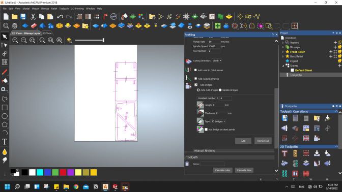
then on the menu on the right clicked on toolpath and choose profiling where I will set all the settings
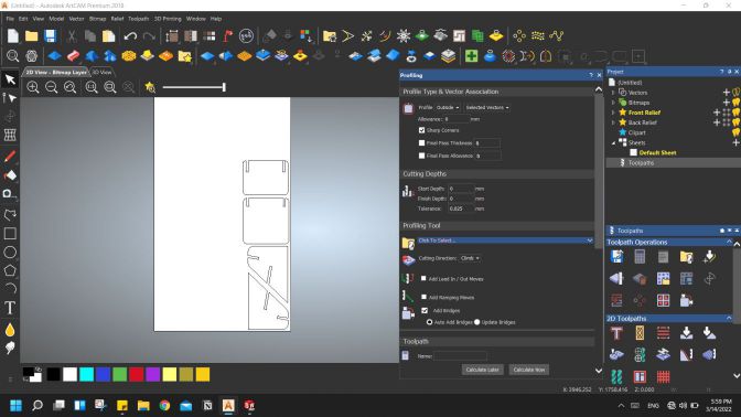
Then choose the stockthickness to be 18mm and the step down was 4mm per path then added tabs - here they are called bridges - so set it to be 4 tabs per path, but here found a problem, as shown in the picture the program read the DXF file as each line on its own not a closed curve. Which made a problem generating a toolpath when I tried to ignore it. so I tried some features in Artcam to join lines or weld them or any other tool that seemed helpful but unfortunately they all couldn't help. so I returned to Fusion to see if I can do anything about it, many trials made short. The solution was to draw a sketch on the components or the body after extruding generating a sketch that has continued outline around it. so exported the new DXFs and went again to ArtCAM.
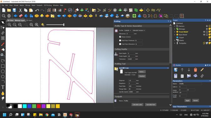
Finally after clicking on "Calculate Now" button it will generate a toolpath which is shown as an offest outline outside my design.
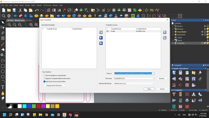
Now that the toolpath is ready I saved it with the extension that the workshop recommended as follows
Then also wanted to see how many time it may take on the machine so it appeared to take around 30 mins as an estimation.
Machining
Annndd done, now all we had to do was to go to the workshop itself. so first thing was to test the runout so we ran a test design consisting of 2 through connection.
Then put on the test wooden piece and moved the axes through the controller then ran the file. So omar replaced the end mill that was on the machine with the 4mm one and then we started the file it took around 4 mins machining and it was ready!
Then we tried the sample and it was pretty good easy fitting!
It seemed the runout was 0mm so I my design didn't need any editing and started cutting it.
Surpisinggly it took less than 15 mins and it was all done and cut!
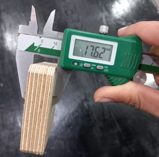
After getting it out of the machine I was so excited to test the parts as the fit was easily assembled by hand like the joint we made, so tried two parts together and.. they didn't fit :D I didn't know why at that time so decided to go back to the lab either ways and work it through. The next day I wanted to make sure that the thickness of the wood was the same as my design. so I first checked the sample we made... and its thickness was 17.7mm not 18mm!
Assembly
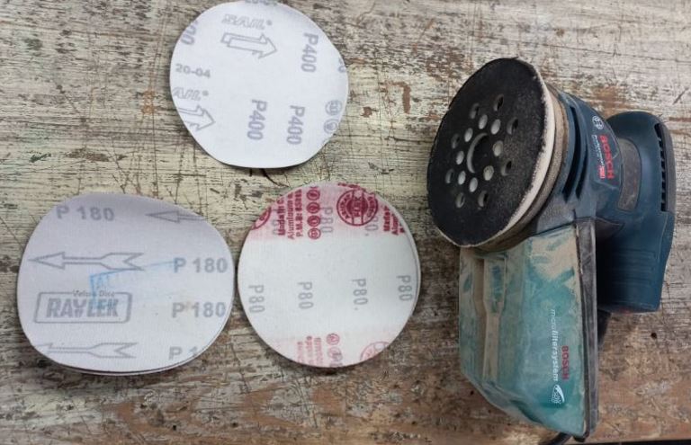
We should have made the test part from the same sheet we used for cutting but we didn't :"D so that 0.3mm difference needed to be cut off, and so I did in the assembly. I used sand paper to make the wood smoother and mainly take off some of the thickness, after and hour or two it was finally assembled :D
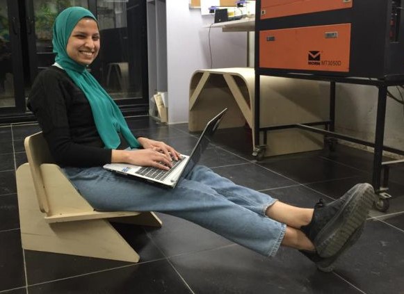
I was so excited to finally try sitting on it, I was a bit afraid it wouldn't bear the load of my body which is around 55 kgs or maybe 60kgs after winter season :"D but it was strong and I felt so happy finally trying it :D
Post-processing
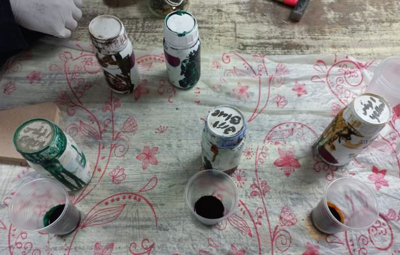
I had a last hour or two. After making the pieces smooth enough using sand paper, I decided to try painting it with wood die, It's amazing how quickly the wood absorbs it and how so little quantity can fill wood areas! We had yellow, green and blue dies so I tried it first on the back then up-front. searched online for paint patterns that may help and finally reached this output. I really like the yellow color on plywood, it looks really up-lifting and cute, like it can be used in a kindergarden with little kids playing around it.
Source files:
Individual Assignment files
Fusion360 FileBack DXF
Side DXF
Seat DXF