


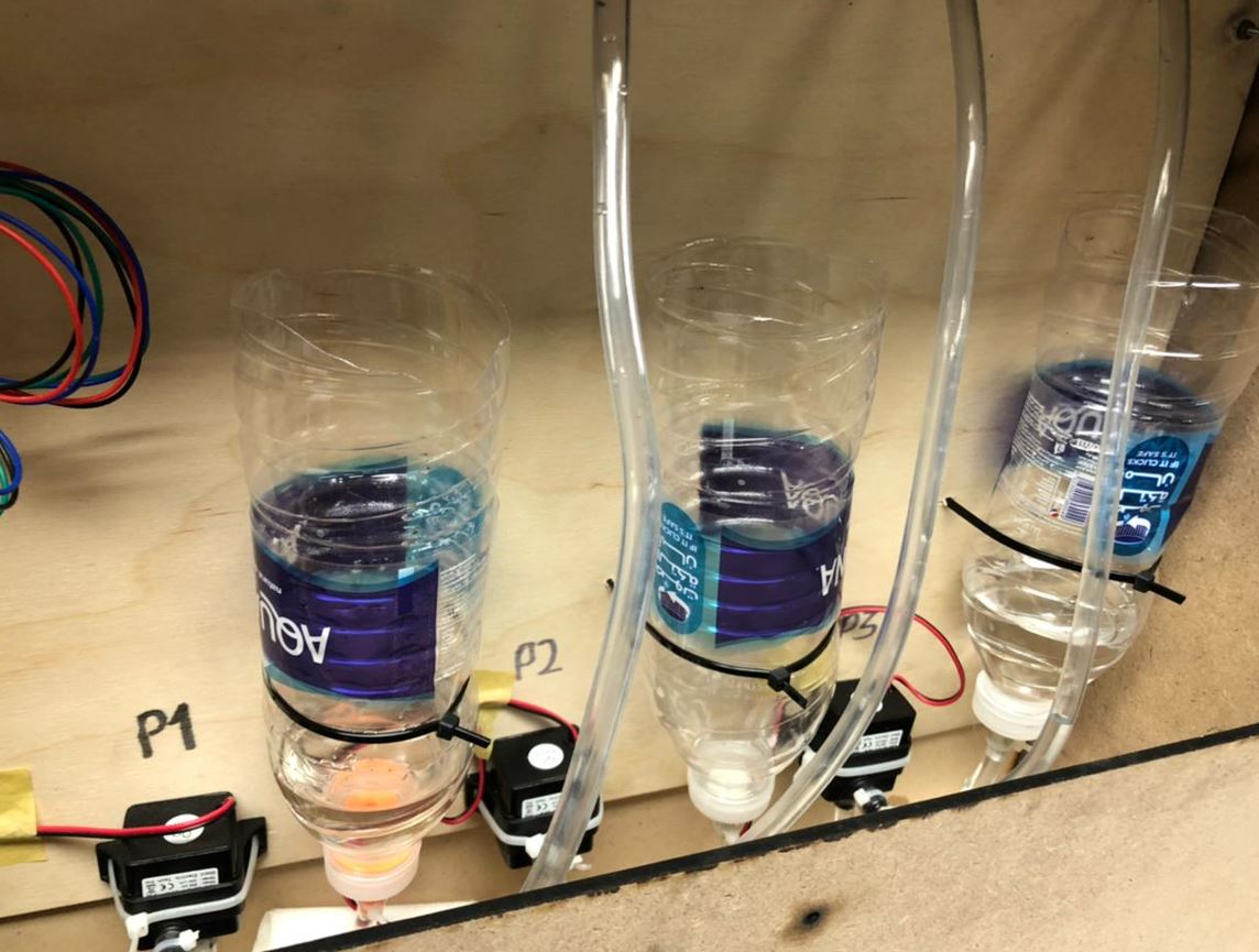
Proudly presenting to you MOAO Coktail Machine, like old school we named it after our names initials xD. Here is our spiral development, first spiral was to made 1 pump work then 2nd spiral was for 3 pumps and the mixer to work.
Let's start from the besinningWe stayed all together and discussed what projects are we interested in, after a few ones we found a cocktail machine that sounded cool from a former student in Fab Academy. here is his project Then we divided the modules. My part was X-axis that we will put the cup on. Controlled by a stepper motor. Also the user interface part which was an LCD and rotary encoder to display a menu for the user to choose his drink from.
 X-Axis Design, Fabrication, Implementation.
First of all we sat down deciding the overall dimensions of the machine so each of us could start designing his module. We agreed that the enclosure will be cut using a laser cutter. Dimensions are as follows:
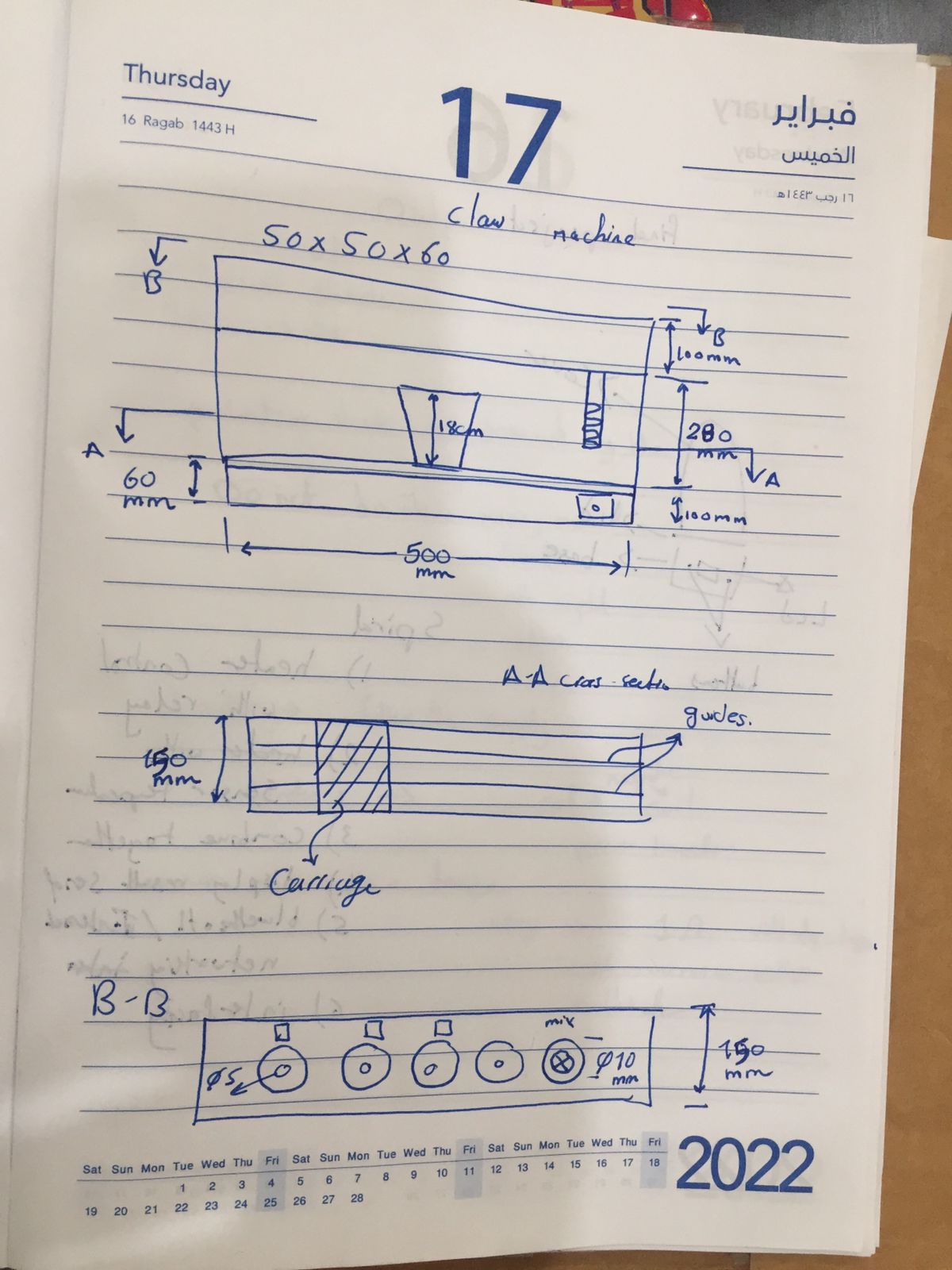
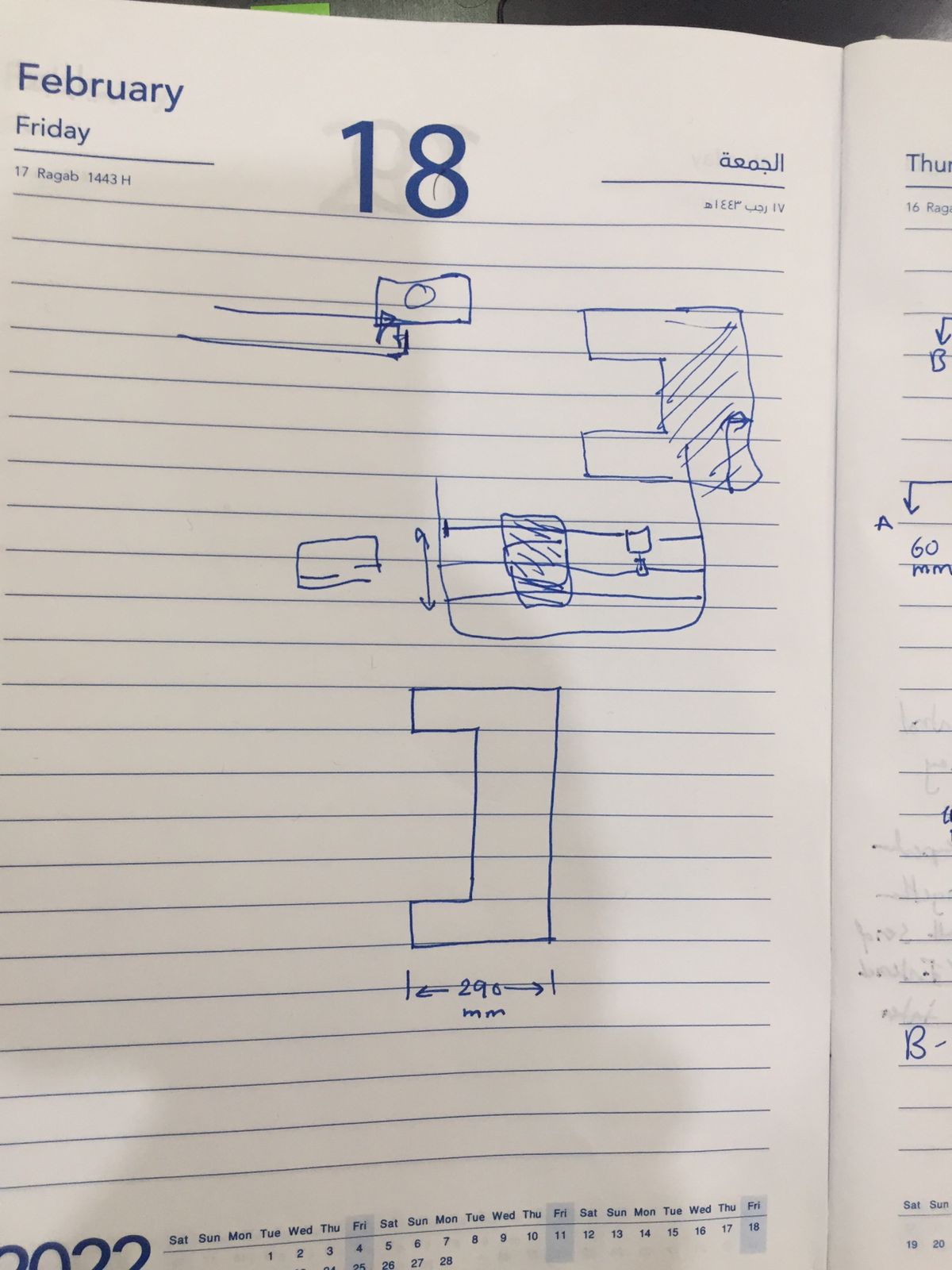
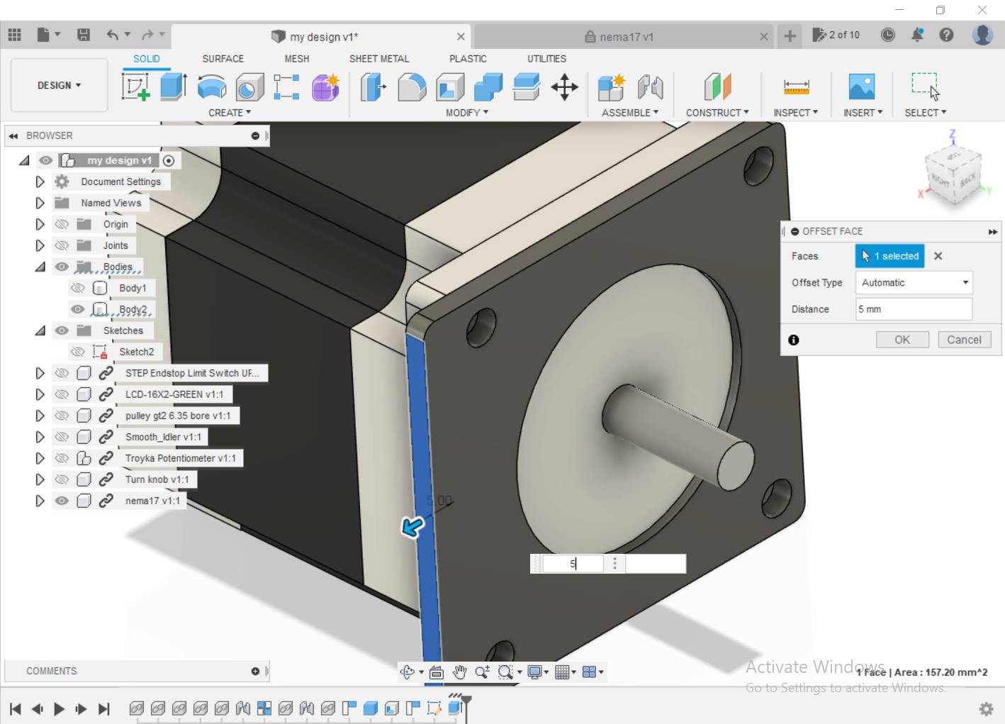
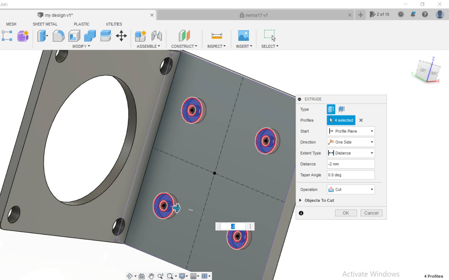
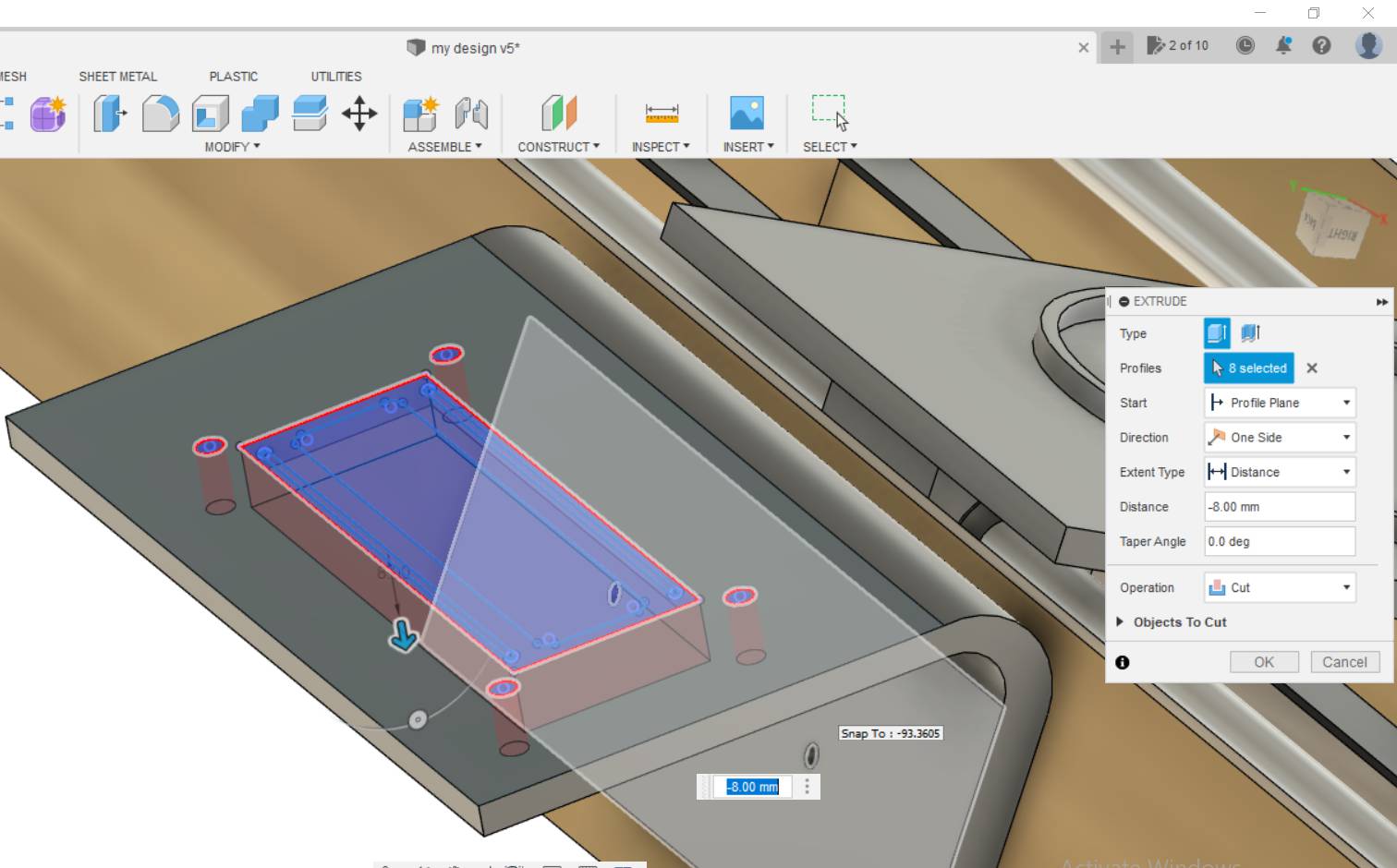
So opened Fusion 360 and started designing, first drew the space I will be limited to then designed inside of it. Then I downloaded ready step files of all the components I will use from Grabcad, It was really very helpful as I was able to visualize 85% of the mechanism and movements after adding them to my design, will be attached below with my f3z design. So, I started building mounts for the stepper motor and made holes to be fixed later using screws and nuts.
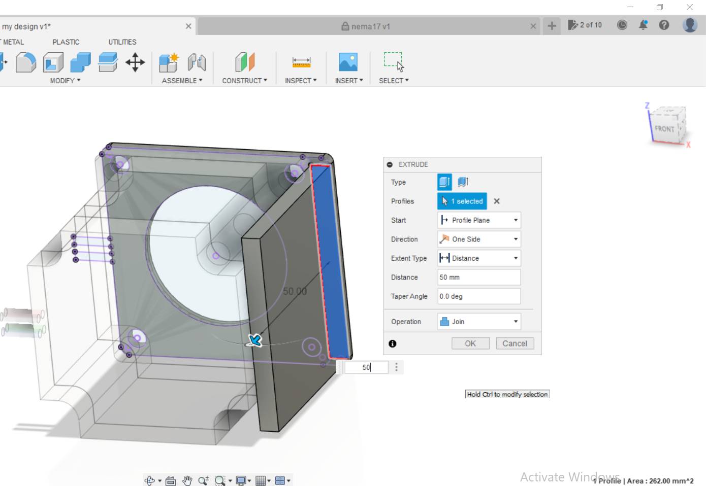
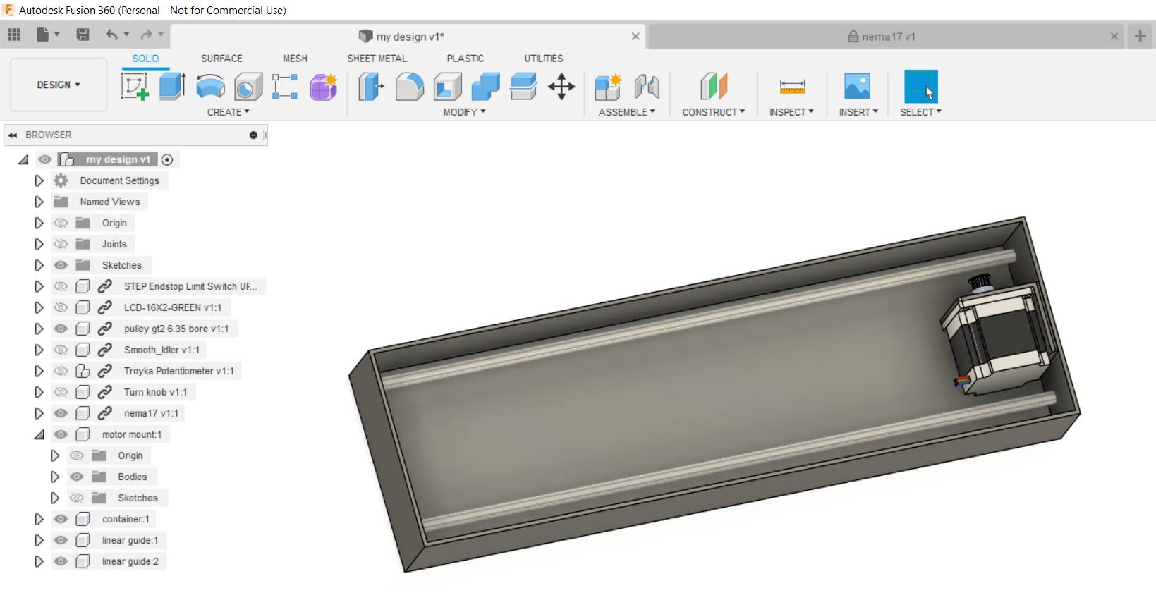
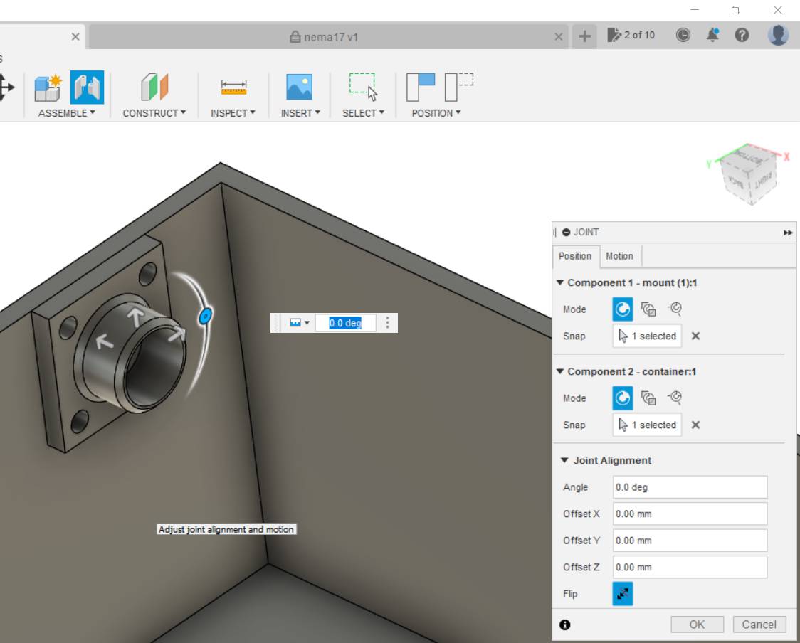
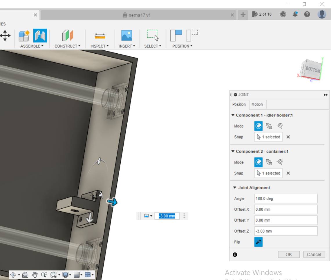
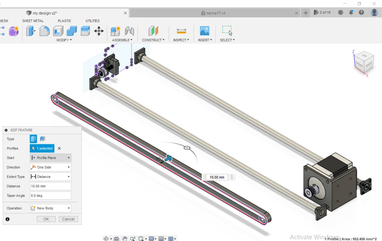
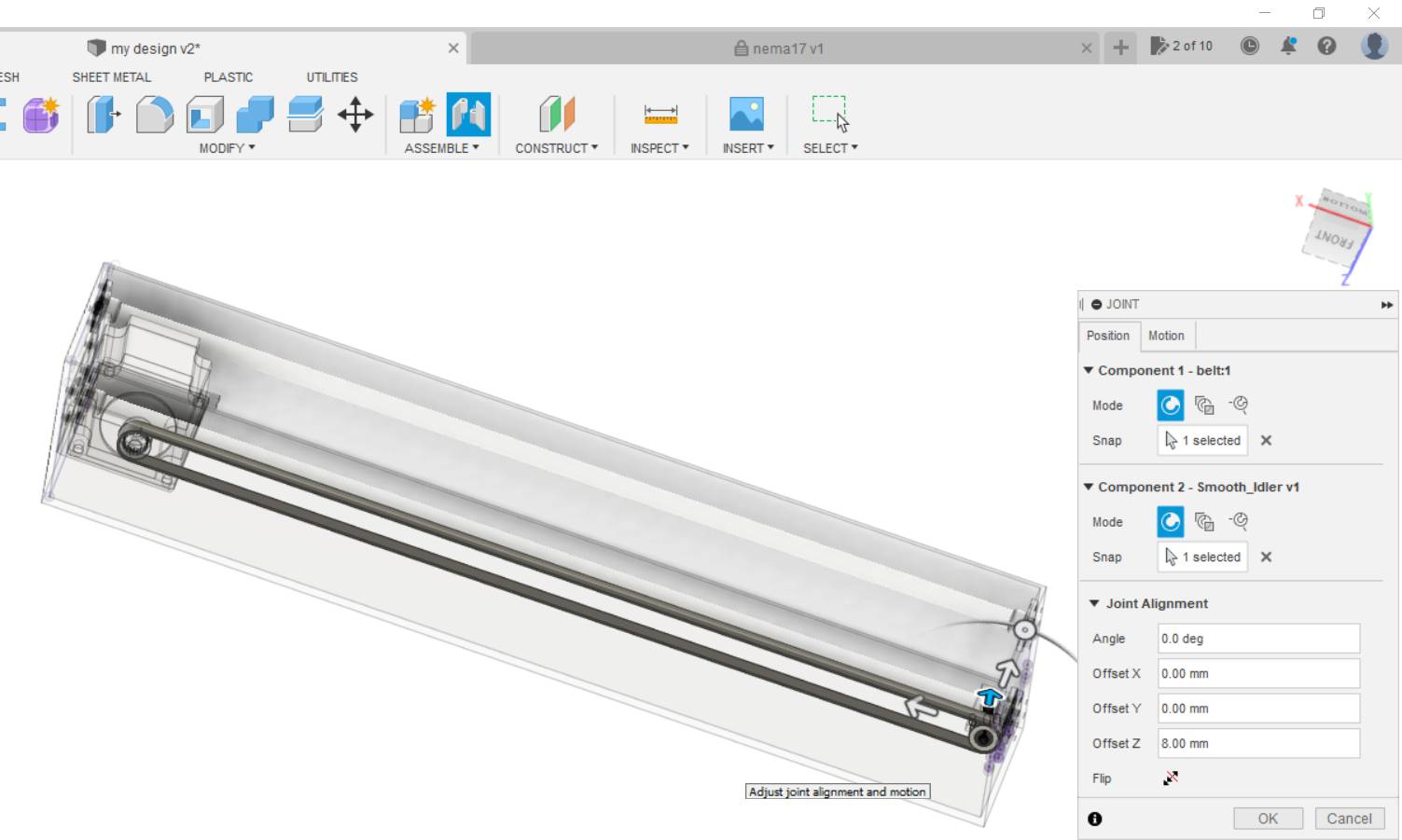
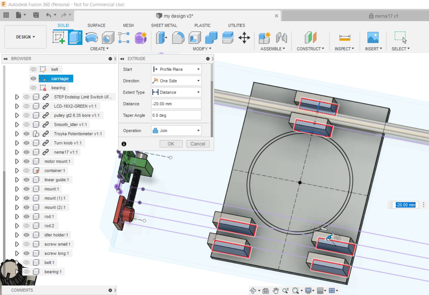
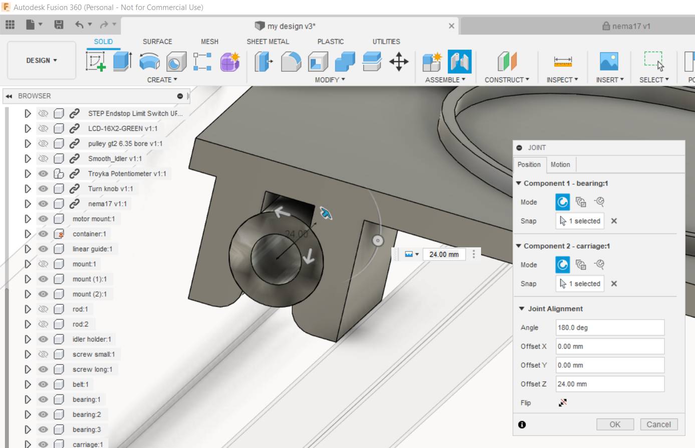
Then added fixations for the linear guides that will help the linear motion in the X-axis. I descided to use timing belt and timing pulley with the stepper motor, just like Prusa 3D Printer mechanism. so made a joint with the timing pulley and motor's shaft and a mount for the idler pulley at the rear end. Then added a belt by drawing staright lines between the 2 pulleys in the cross-section area of the belt and then used extrude.
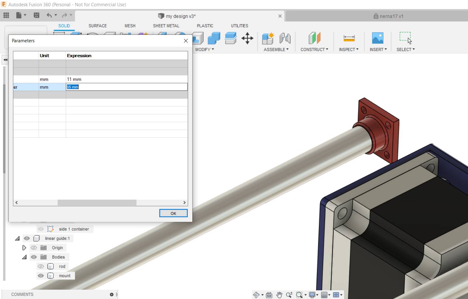
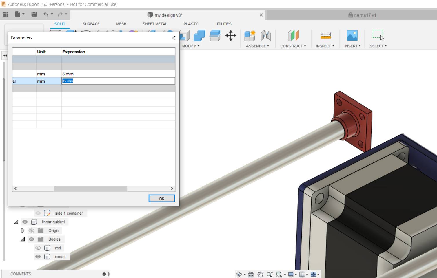
Just in case I didn't find the beam diameter I needed so I made the rod size parametric so I can easily change the mounts later on if needed
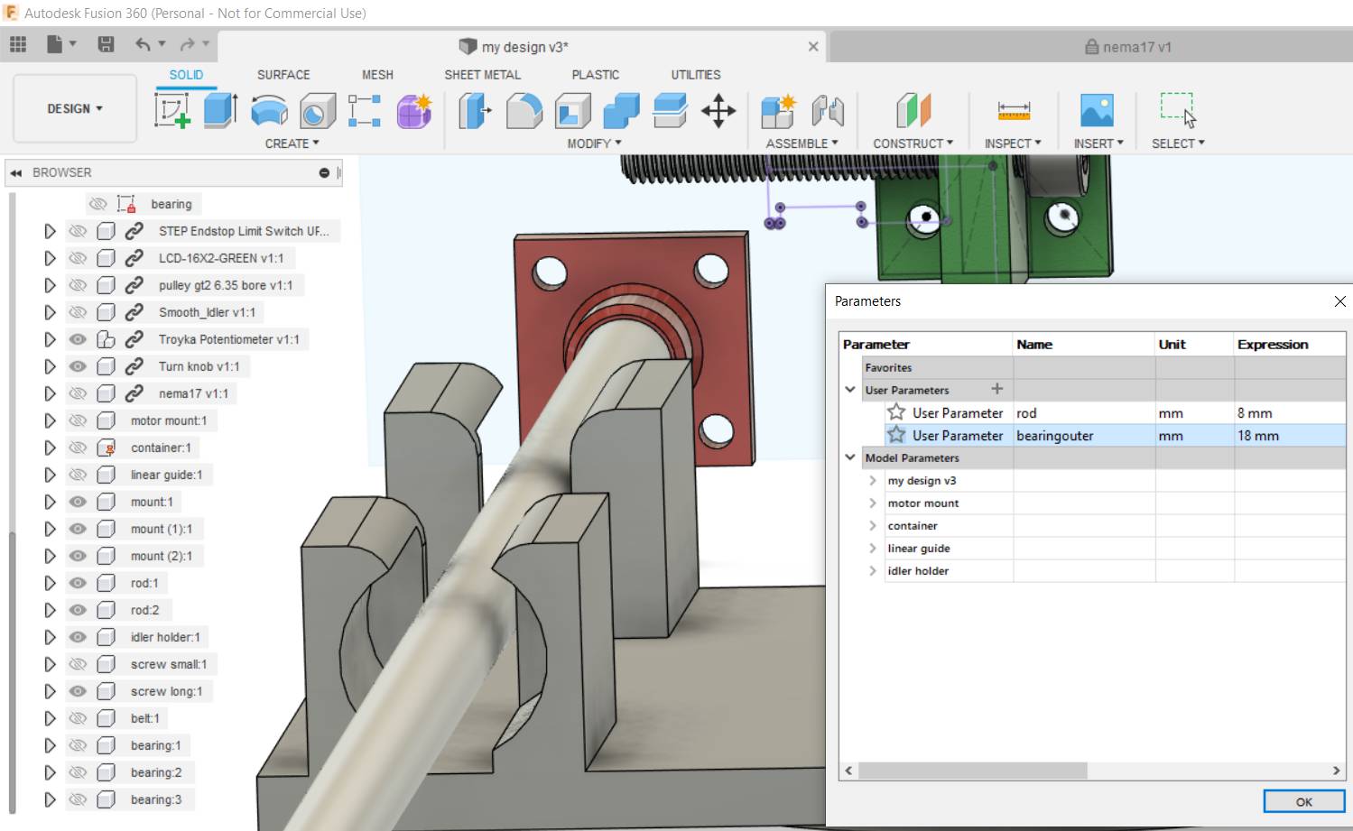
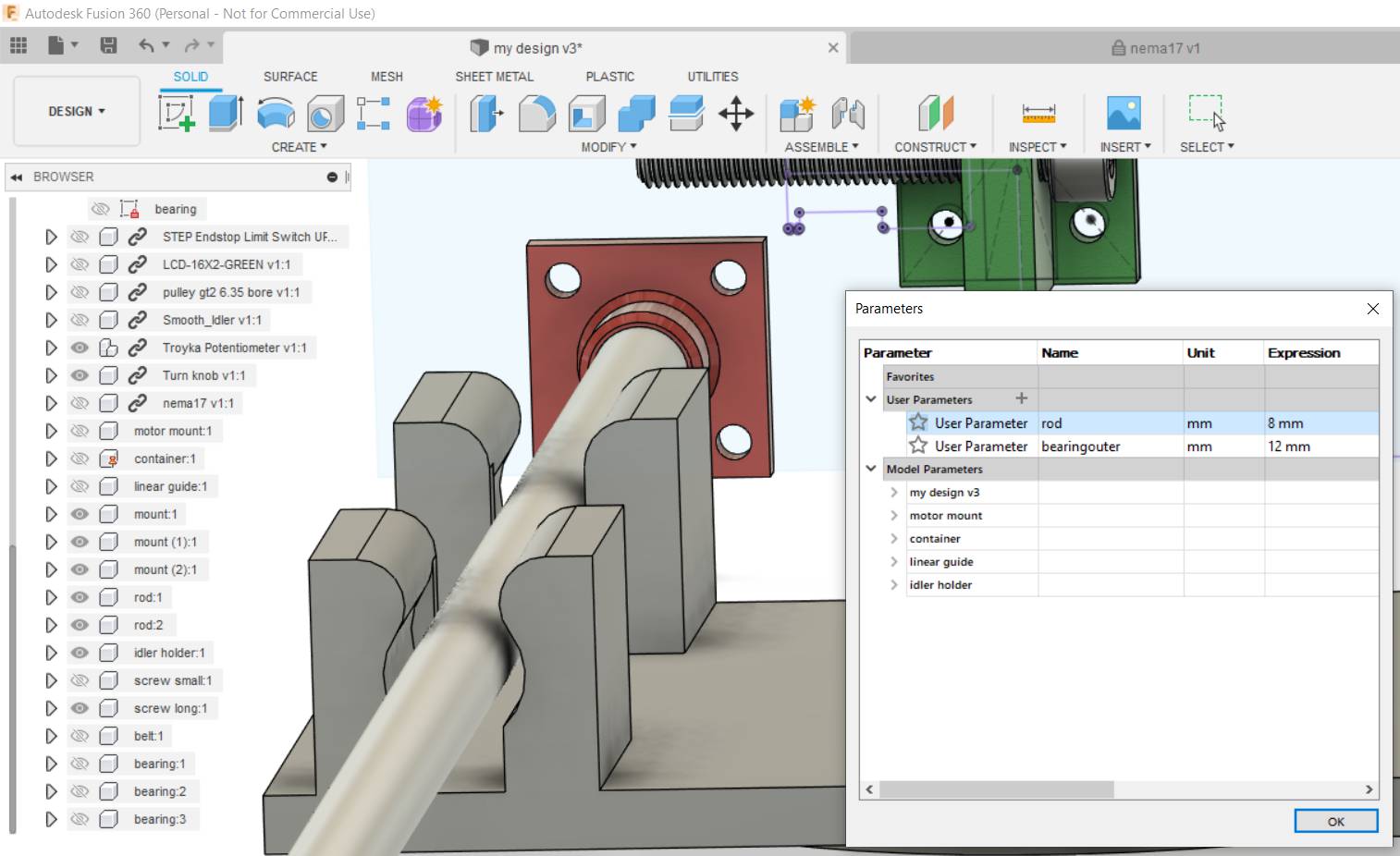
Then started designing the carriage that will hold the cup in place. I just drew a rectangle then added little cubes down side and cut the bearing from them. Also made its diameter parametric as if the rod dia is 8mm the bearing outer diameter would be 15mm but if the rod dia was 10mm the bearing will be 18mm, based on the bearings datasheet.
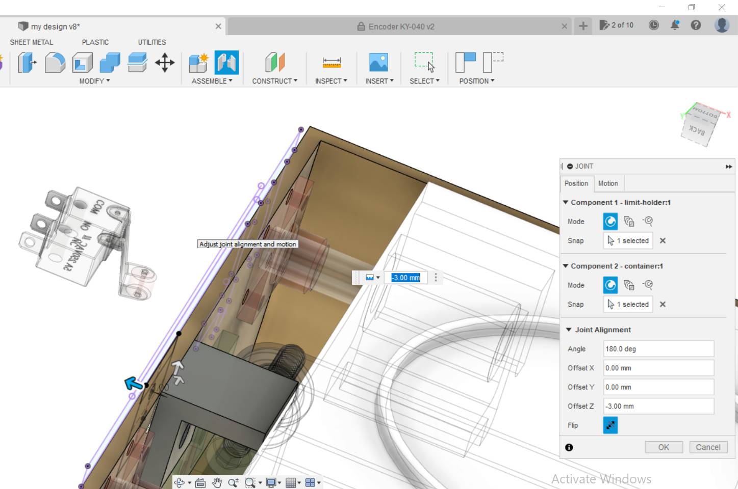
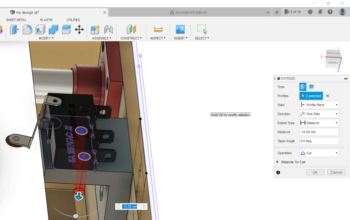
Finally added limit switch at the start of the axis away from the stepper motor, made a mount and X-axis was doone!.
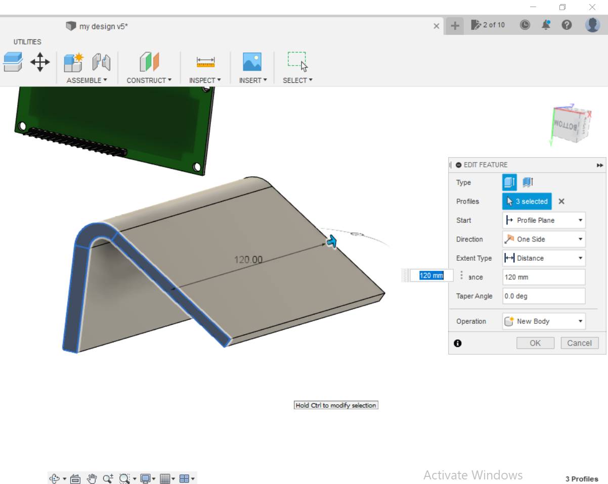
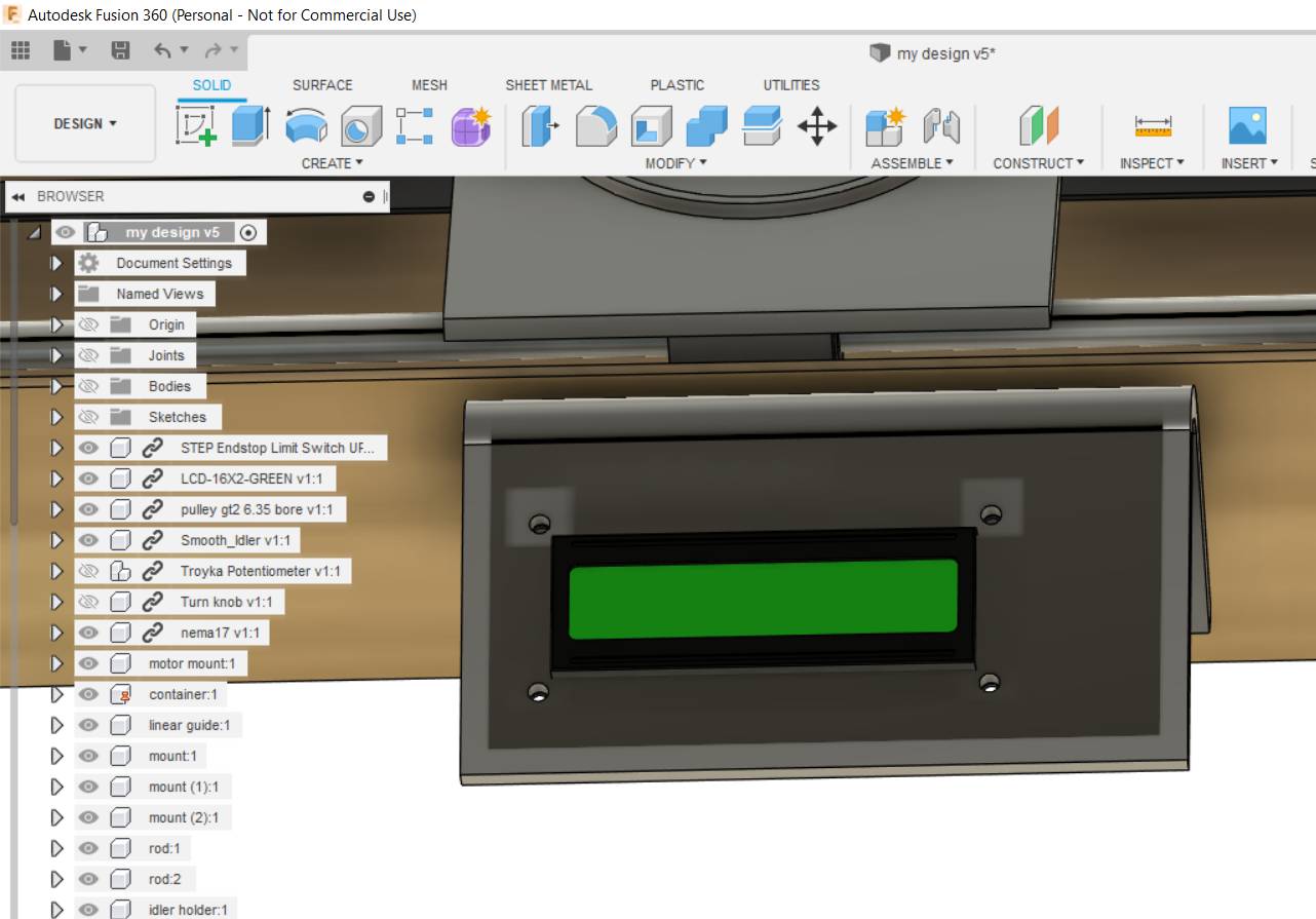
Now comes UI. I wanted it to be simple so I just made 1 open part that will hold the LCD and rotary encoder together.
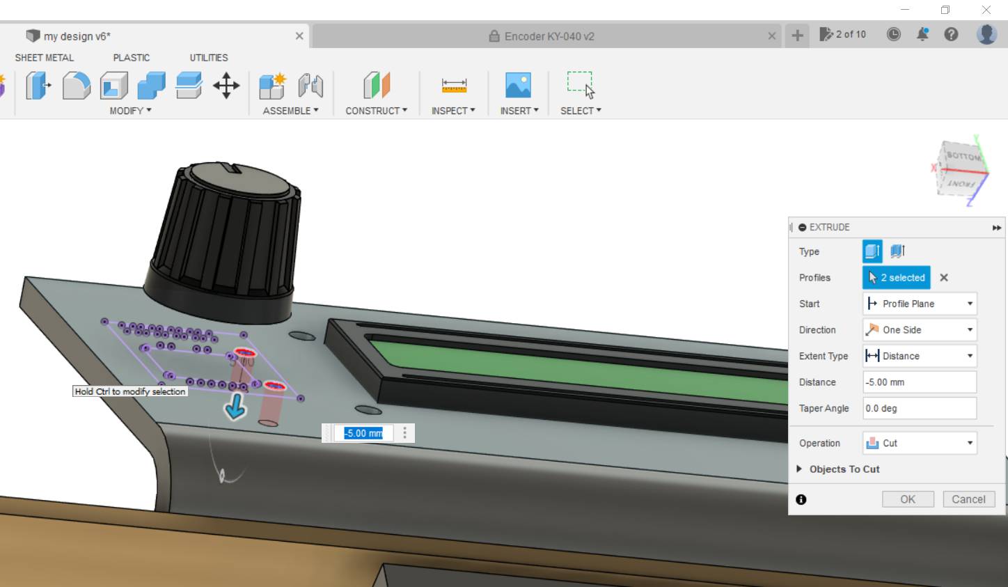
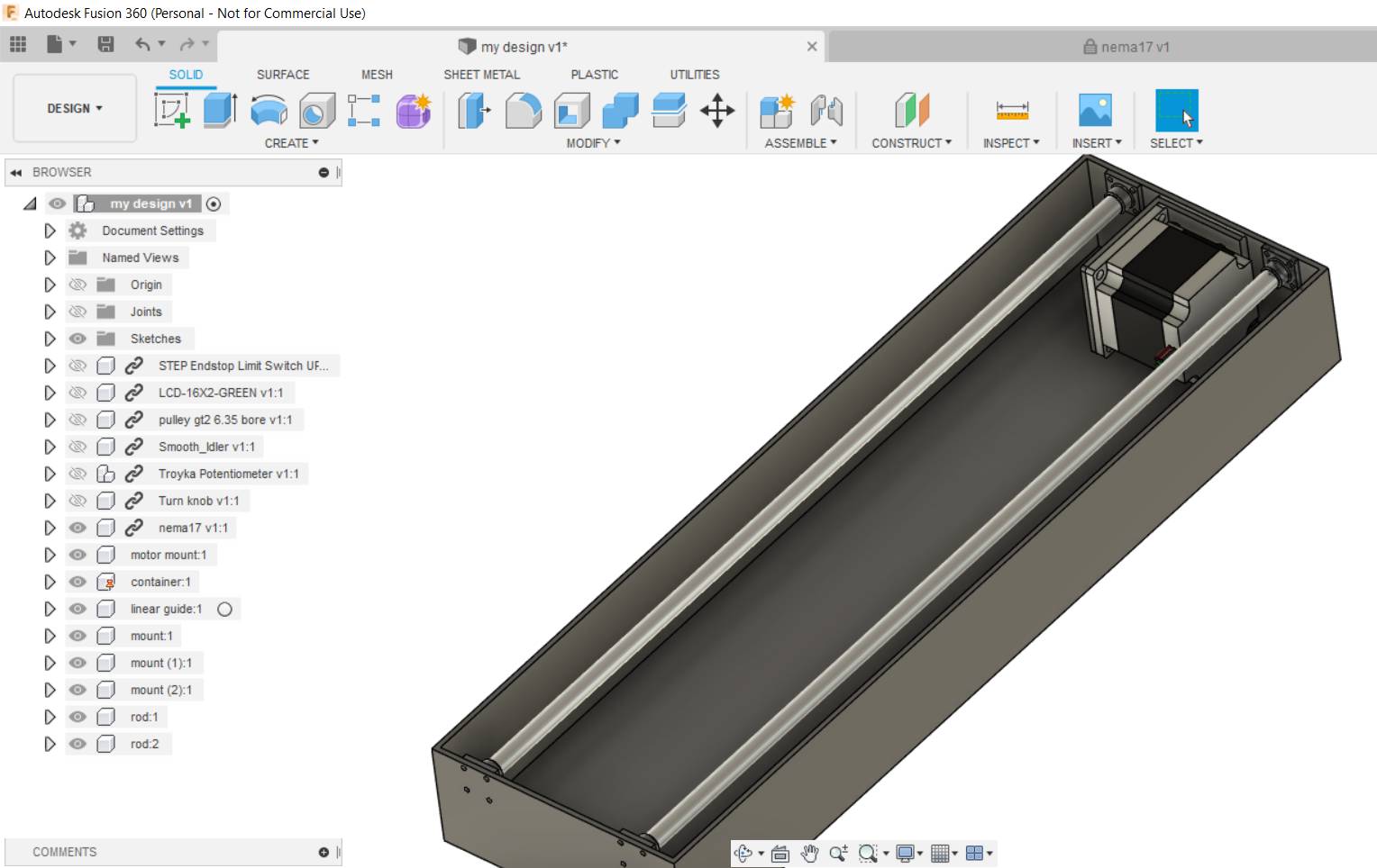
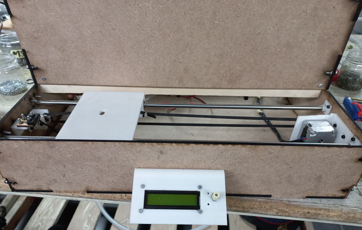
Take a look after the X-axis was done.
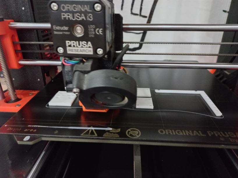
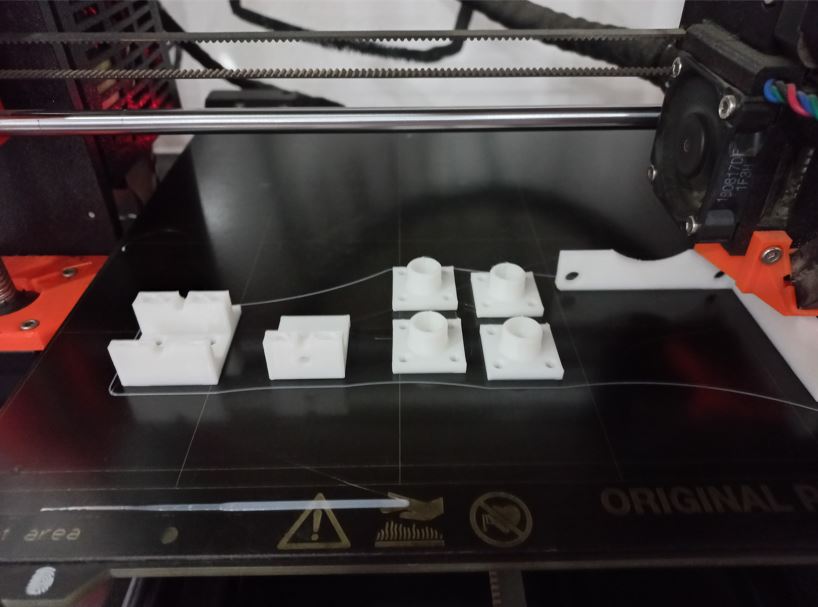
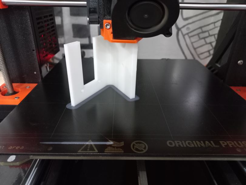
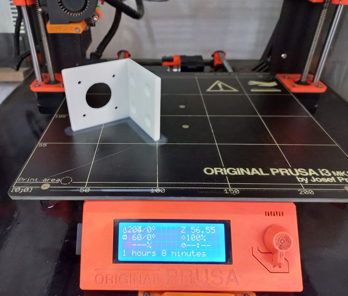
Fabrication and assemblyAfter each of us finished his assigned module one of us was assigned to integrate all modules in 1 design which were X-axis, UI, Mixer mechanism and pumps with its containers. After the integration was done we started fabrication, so I 3D printed all the mounts I made, here is a peak while printing.
Then started assembling all together.
 UI coding
It was my first time dealing with a rotary encoder so I searched for similar projects for refrence and to learn how it works. Then found this tutorial which also had a menu but it controlled a different type of screen, so I used the code but made it compatible with LCD screen and changed the menu items as follows, Also I will be sharing all the codes down in soource files section.
          char menu[][maxItemSize] = {"Juice", "Mix  ", "   "};
          // Only 2 sub-menus are shown.
          char subMenu0[][maxItemSize] = {"Orange", "Lemon ", "Mango ", "BACK   "};
          char subMenu1[][maxItemSize] = {"Mokheto", "Mix2   ", "Mix3   ", "BACK   "};
Moving X-axis
I always dealt with stepper motors using only stepper motor shields mounted on an arduino, didn't try connecting drivers directly before. so, also searched for the circuit and code.Then found this tutorialwhich illustrated the driver's pinout, how stepper motors work, everything really so it was very helpful. So, I made the circuit and connected step and direction pins to Arduino and uploaded the following code to move the motor continuously in 1 direction.
          const int dirPin = 12;
          const int stepPin = 11;
          const int stepsPerRevolution = 200;

          void setup()
          {
            // Declare pins as Outputs
            pinMode(stepPin, OUTPUT);
            pinMode(dirPin, OUTPUT);
            // controlling dirction of stepper to be CW or CCW between HIGH and LOW
            digitalWrite(dirPin, HIGH);

          }
          void loop()
          { //step pin is the one responsible of the movement
            digitalWrite(stepPin, HIGH);
            delayMicroseconds(800);
            digitalWrite(stepPin, LOW);
            delayMicroseconds(800);
          }
It worked as follows
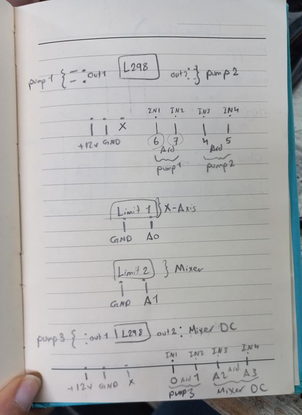
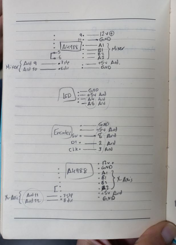
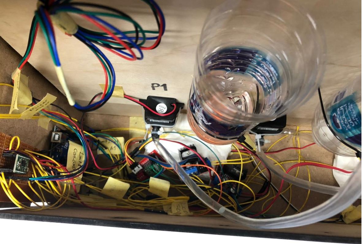
Integration of the whole codeAfter each of us successfully controlled the components of his module we worked all together on making the whole circuit in hardware and redraw it in a quick hand writing. Wire management took so much time but it was important for easier debugging if anything went wrong. the whole circuit was as follows:

Then we made the code. It was built over functions to make it easier to understand and as logical and tidy as we could. The code starts with the welcoming screen and making X-Carriage and mixer stepper motor to home "click the limit switchs" then all the rest was built over switch cases, case0, case1..etc. which when "true" calls a function as well. for example: if the user chooses Orange juice which is option 1 then it calls pump1 function, which states to move X-axis from the home position to pump1 position then opens pump1 for specific time too fill the cup then homes again. it was all pretty similar to each other just controlling different pumps.
            switch (itemSelected)
            {
            case 0: // juice is choosen
              Serial.print("calling submenu");
              subMenuSelected = displayMenu(subMenu0, sizeof(subMenu0) / maxItemSize);
              switch (itemSelected)
              {
                case 0: // Mango
                  pump1();
                  break;
                case 1:
                  pump2();
                  break;
                case 2:
                  pump3();
                  break;
              }
              break;

            case 1: // Mix is choosen .. etc
            }
That was the basic structure of the code, let's look at the functions. To home we used simple while loop with a condition. the limit switches were input_pullup so it was always reading high unless it was pressed. So, while the reading is high move the motor and it keeps checking the condition so once the limit switch is pressed it doesn't go inside the while loop so the motor stops.
          void homing() {
            while (digitalRead(limitX) == HIGH) {
              rotateX(1, 1);
            }
            while (digitalRead(limitM) == HIGH) {
              rotateM(0, 2);
            }
          }
Pumps functions are just like we described above, the difference between each funstion of pump1 and pump2 is that they control different pins attached to different pumps.
          void pump3() {

            // move stepper specific cm "pump3 position"
            rotateX(1, 5);
            //pump3 working
            digitalWrite(pump031, HIGH);
            delay(5000);
            digitalWrite(pump031, LOW);
            // move stepper to home
            homing();
          }
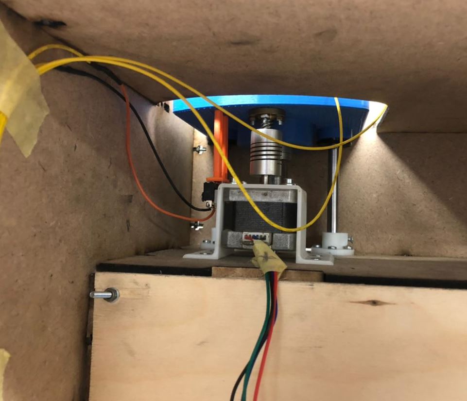
The mixing function was the longest as the X-axis moves to 2 different pumps positions and 2 different pumps dispense 2 different fluids + after they finish the X-carriage moves to the mixer postion, Then mixer stepper moves down and the mixing motor starts rotating then stops then mixer stepper move up then X-carriage homes back to its home position.
          void mix1() {

            // move stepper specific cm
            rotateX(1, 7);
            //pump3 working
            digitalWrite(pump031, HIGH);
            delay(1000);
            digitalWrite(pump031, LOW);
            // move stepper to pump2
            rotateX(0, 3);
            //pump2 working
            digitalWrite(pump021, HIGH);
            delay(1000);
            digitalWrite(pump021, LOW);
            // move stepperX to mixer position
            rotateX(1, 10);
            // move stepperM down
            rotateM(1, 5);
            digitalWrite(motor1, HIGH);
            digitalWrite(motor2, LOW);
            delay(2000);
            digitalWrite(motor1, LOW);
            digitalWrite(motor2, LOW);
            // move stepperM up
            rotateM(1, 5);
            homing();
          }
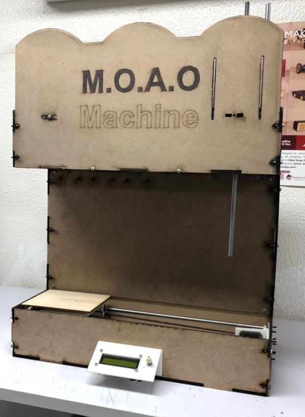
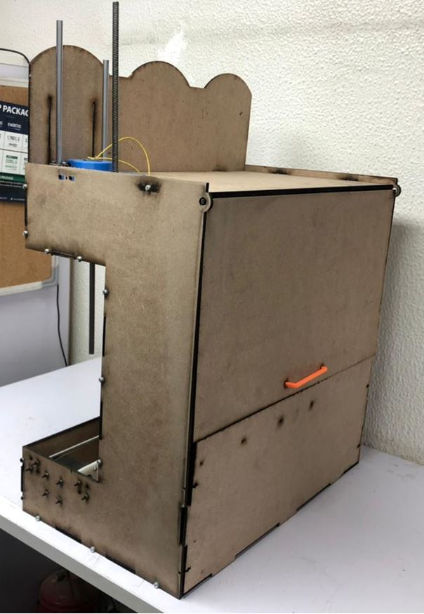
And that was it :D Here are some photos of the projects after it was all assembled and working.
 Source files:
Fusion design
Source files:
Fusion design Complete Arduino code