Interface and Application Programming Assignment


The group assignment was to compare as many interfacing tools and applications as possible. So we tried Processing, Scratch for Arduino and MIT App Inventor. Next I will explain each in more details.
It is a very easy tool to code Arduino using block programming by an interfacing tool that you can download from their offical website in here. first step is to download the application and also download the firmware that you will burn on Arduino. Then the Arduino will be connecting with the program in your laptop. The program window is divided to 3 main sections, on the right there are the blocks you will use, middle one is the scripting section where you build your code, and on the right is a where any readings from Arduino Analog pins appear plus you will find start and stop buttons to run your code.

we first tried simply turning ON a LED then OFF. so we connected the Arduino with the laptop and connected a LED to pin 10 in Arduino and Ground. on the blocks we just sent HIGH to pin 10, then delay, then sent LOW then delay.
Then we wanted to try also an RGB LED, so we noticed there is a random block in scratch so we used it to generate a random number between 0 and 255 so it can change the LED color, so we got many different color colors.
Finally we wanted to try reading an input and based on it control an output. so we tried reading a potentiometer then taking its input we made a LED fade. in the next video you will notice the reading chaning on the inputs section.
First our instructor made a board that have 6 LEDs and having ATtiny44 as its MCU. Then he build a processing code so when he push on a specific button it can turn on a LED controlling all 6 LEDS. which was an interesting intro. So after that each of us used processing to control 1 LED. The next images shows Kamel's application.


I made a simple program that has only two buttons "ON" and "OFF". I first downloaded Processing from There offical websiteI downloaded 3.5 version. Then found also on there website great tutorials that helped me understand the GUI. Then to make interfacing applications easily I used controlP5 library. So the code sequence was as follows: imorting controlP5 library then in void setup was the seze of the greated screen then created 2 buttons on and off, setting their size and colors and that was it.
          import controlP5.*;

          ControlP5 cp5;

          int myColor = color(128);

          void setup() {
            size(400, 600);
            noStroke();
            cp5 = new ControlP5(this);

            cp5.addButton("ON")
              .setValue(128)
              .setPosition(140, 300)
              .updateSize()
              ;

            cp5.addButton("OFF")
              .setValue(128)
              .setPosition(210, 300)
              .updateSize()
              ;

          }

          void draw() {
            background(myColor);
          }
The application was done but needed to communicate with Arduino. so I used Serial library in processing to communicate with the port I connected Arduino on, and then made another code to Arduino so it it can read from serial and based on that reading turning on and off the LED.
so what I added in the processing code was importing Serial library then created an object from Serial class called myPort which I spcified its COM poet and baud rate. Finally from controlP5 made a functions that detects any evet happening "clicking on any button" then made two more fuctions that communicate with Serial, If on button pressed sent 1 if OFF button pressed sent 0.
          import controlP5.*;
          import processing.serial.*;

          ControlP5 cp5;
          Serial myPort;  // Create object from Serial class

          int myColor = color(128);

          void setup() {
            size(400, 600);
            noStroke();
            cp5 = new ControlP5(this);


            cp5.addButton("ON")
              .setValue(128)
              .setPosition(140, 300)
              .updateSize()
              ;

            cp5.addButton("OFF")
              .setValue(128)
              .setPosition(210, 300)
              .updateSize()
              ;

            String portName = Serial.list()[0]; //change the 0 to a 1 or 2 etc. to match your port
            myPort = new Serial(this, portName, 9600);
          }

          void draw() {
            background(myColor);
          }

          public void controlEvent(ControlEvent theEvent) {
            println(theEvent.getController().getName());
          }

          public void ON() {
            myPort.write(1);
          }

          public void OFF() {
            myPort.write(0);
          }
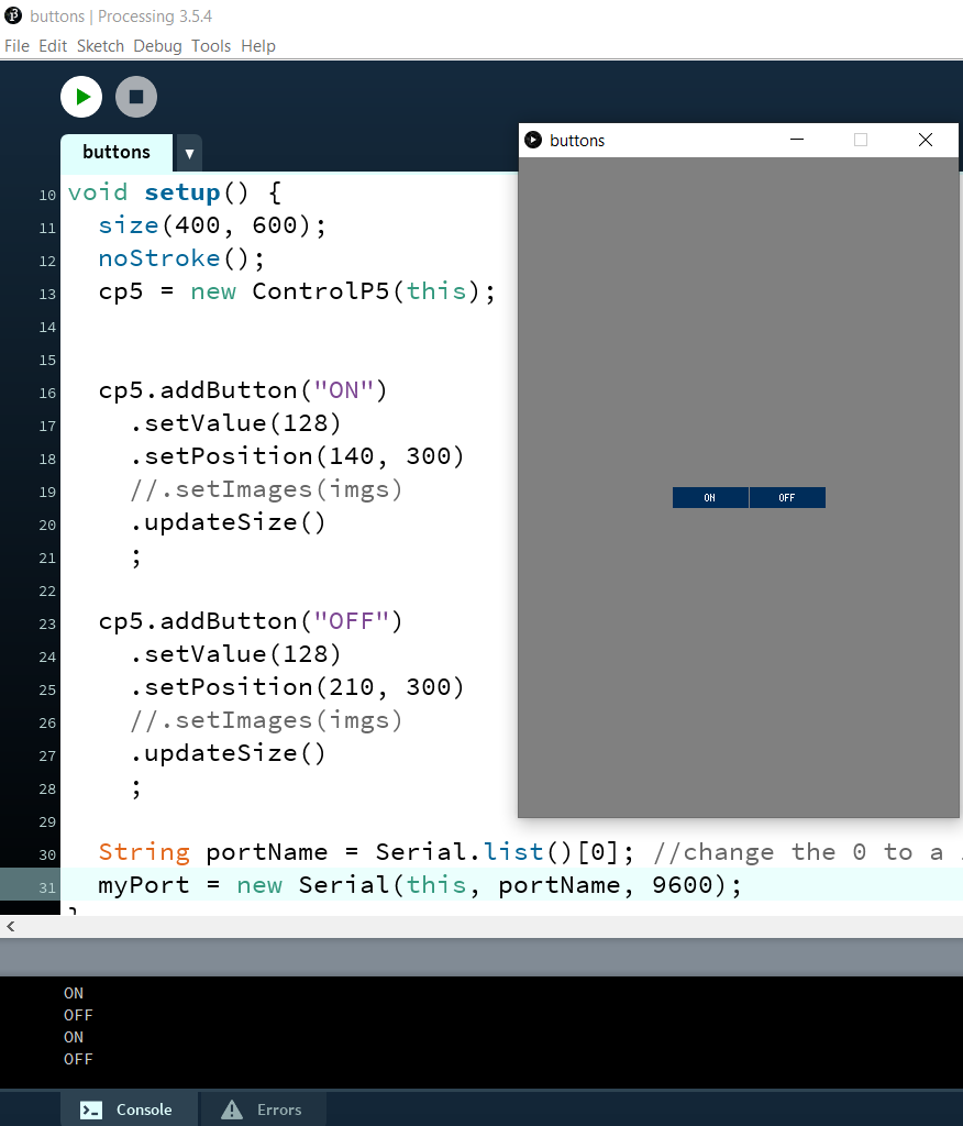
Here is what's appeared when I ran Processing code.
The Aruino code was simple. Reads from Serial then compares the reading with 0 and 1 if 1 was sent, turn the LED on "make its pin HIGH" if 0 was sent turned the LED off "make its pin LOW".
          int val = 0;

          void setup() {
            Serial.begin(9600);
          }

          void loop() {
            while (Serial.available()) {
              val = Serial.read();
              Serial.println(val);
            }
            if (val == 1) {
              digitalWrite(7, HIGH);
            }
            else if (val == 0)
            {
              digitalWrite(7, LOW);
            }
          }
And it worked perfectly.

I made my assignment by making two applications, One controls LED in my ATtiny44 board by a mobile application I built through MIT app inventor, The second reads the reading on a potentiomete then makes a circle bigger or smaller based on the reading which I made through processing. Lets dive in more deep into each.
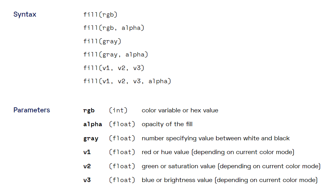
I built my code based on a code I found in processing tutorial on their website, Here is its link. Then started with searching about the lines they used to draw the circle and changing its filling color, etc.. so found its parameters which helped me edit the code as I needed.

Then added Serial port and its needed lines to communicate with Arduino like I described in the group assignment, then made it read the reading coming from serial and put it into a variable and based on that variable it draws the ellipse and changing its filling color. So following is my final processing code.
          import processing.serial.*;

          Serial myPort;  // The serial port
          void setup() {
            // List all the available serial ports
            printArray(Serial.list());
            // Open the port you are using at the rate you want:
            myPort = new Serial(this, Serial.list()[0], 9600);

            size(640,360);
            noStroke();
          }

          void draw() {
            while (myPort.available() > 0) {
              background(0);
              int val = myPort.read();
              println(val);
              fill(255, val, 0);
              ellipse(width/2, height/2, val, val);
            }
          }
The Arduino code was simple as I conected the potentiometer with an Analog pin in my ATtiny1614 board then put its reading into a variable and sent its value to processing via Serial. so Here is my Arduino Code.
          #define sensor 10
          int val;

          void setup() {
            // put your setup code here, to run once:
            pinMode (sensor, INPUT);
            Serial.begin(9600);
          }

          void loop() {
            // put your main code here, to run repeatedly
            val = analogRead(sensor);
            val=map(val,0,1023,0,255);
            Serial.write(val);
          }
The connection was as follows: I connected my ATtiny1614 board with the FTDI cable TX,RX pins to be able to communicate with Serial. Connected FTDI cables' VCC and GND to a breadboard so I can take them to power my ATtiny1614 board and also put them in the start and end pin in the potentiometer. Then connected the potentiometer reading pin with an analog pin of my ATtiny1614 board. And it worked ^^
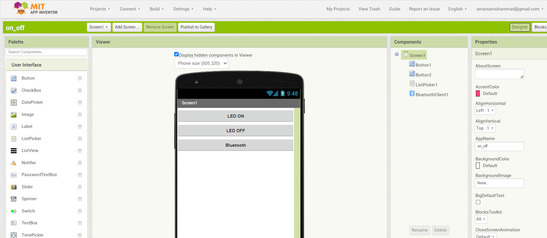
I was an absolute beginner to MIT App Inventor before this week so I needed a big push. and I found one tutorial that helped my a lot and actually followed step by step till I finished my application and worked from the first time too! Here is the tutorial's link The application was mainly built on a list that shows available devices via blutooth, and two buttons that just like processing when pressed sent 1 or 0 via blutooth then the bluetooth module communicates with my ATtiny44 board via UART communication. Here is how my code and blocks looked like:

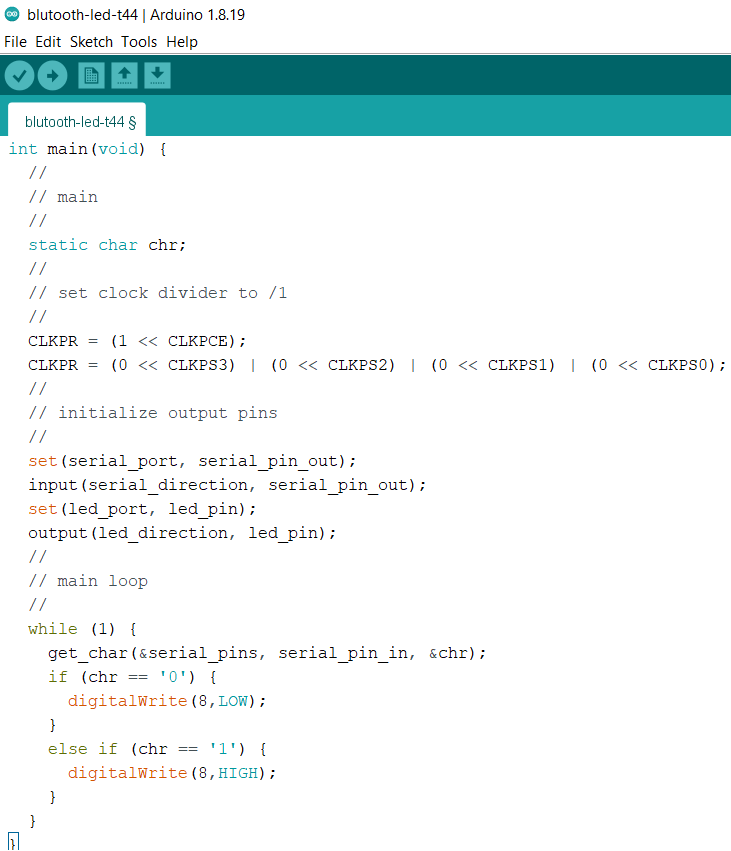
After the application was done I downloaded the file with .apk extension and installed it on my mobile. What was let was the code. As I used ATtiny44 which didn't have UART communication in hardware I used Neil's code "Software Serial" for ATtiny45 and edited some lines to make it compatible with my ATtiny44 board. I just edited the LED pin as it was in portB not A and also serial-pin-in and serial-pin-out with the ones I connected in my PCB design.

Then finally edited the main code to make it turn the LED on and off based on the serial communication input.