


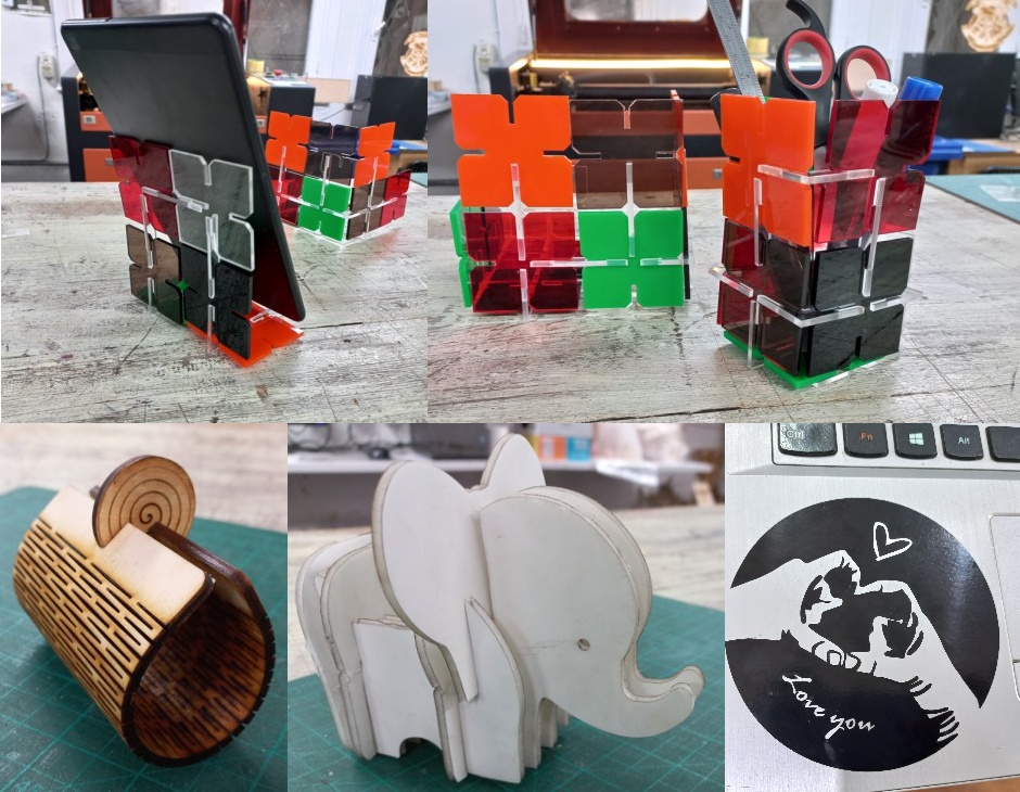
Here is my Hero-shot of the week! Honestly, laser cutting has been always one of my favorite machines.
Let's start first with the group assignment
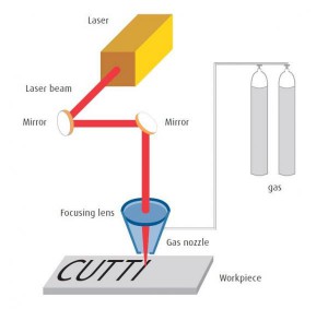
we started with what LASER means, its abbreviation is: " light amplification by the stimulated emission of radiation". So simply, it consists of a laser tube where the photons are generated, then this intense light beam is being mirrored a few times to reach a focus lens then finally the workpiece.
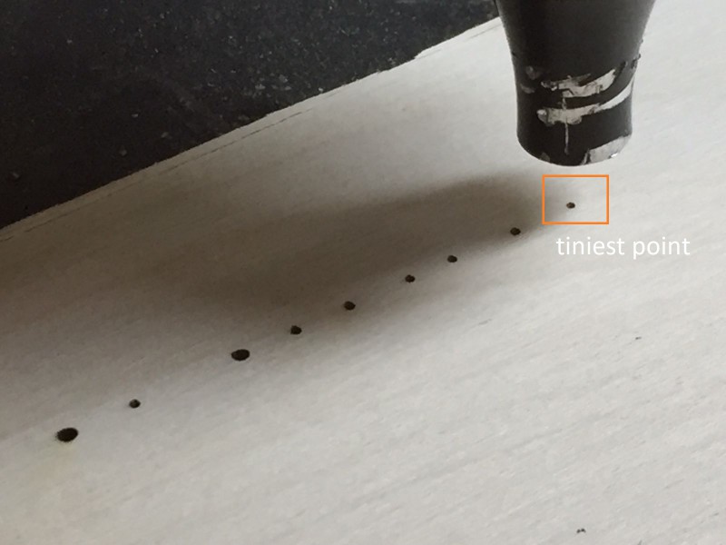
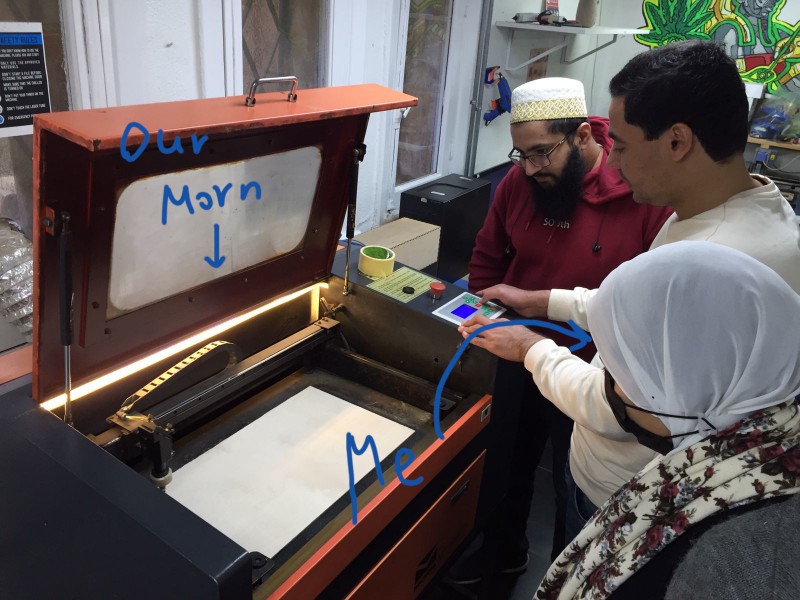
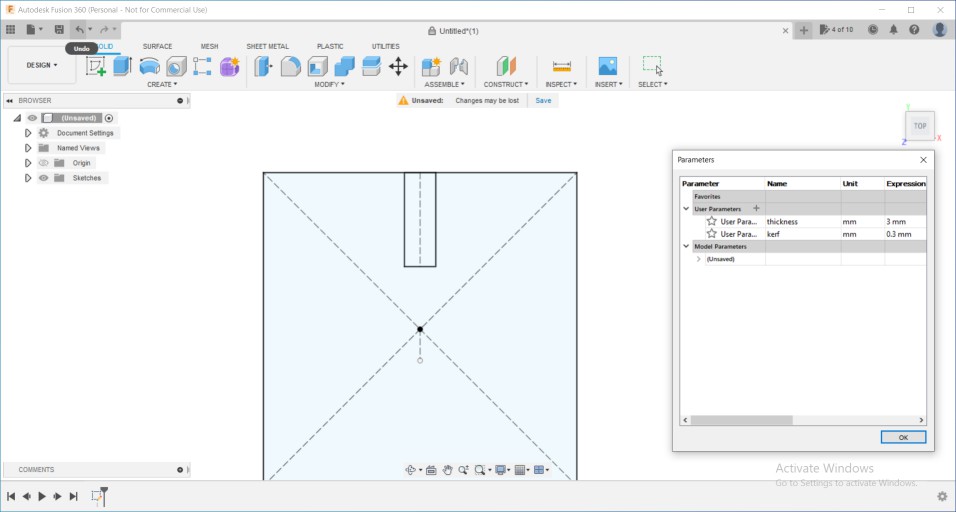
So, to be able to cut on the laser cutter, you must know some parameters first. like the power of the machine, Our Morn is 90 Watts. Also, we need to know the focal lens, which is the distance between the focusing lens and the workspiece or the material we want to cut or engrave on. So, Over all we went through the whole process of testing proper cutting settings " power and speed ", measuring the focus length, measuring the kerf, then each one of us made them again but using other materials. Hence, At the beginning we started out by trying pulses at different distances till we reached the tiniest point which indicates that we finally reached the correct focal length, which was around 6.3mm from the nozzle's head.
Then we started charactrizing plywood with thickness 3mm together and after that each of us had to charactrize different material. to find the proper power and speed - which are cutting settings - we try different speeds and powers till we find the best ones. the proper settings with us were power: 60% and speed: 20mm/s.
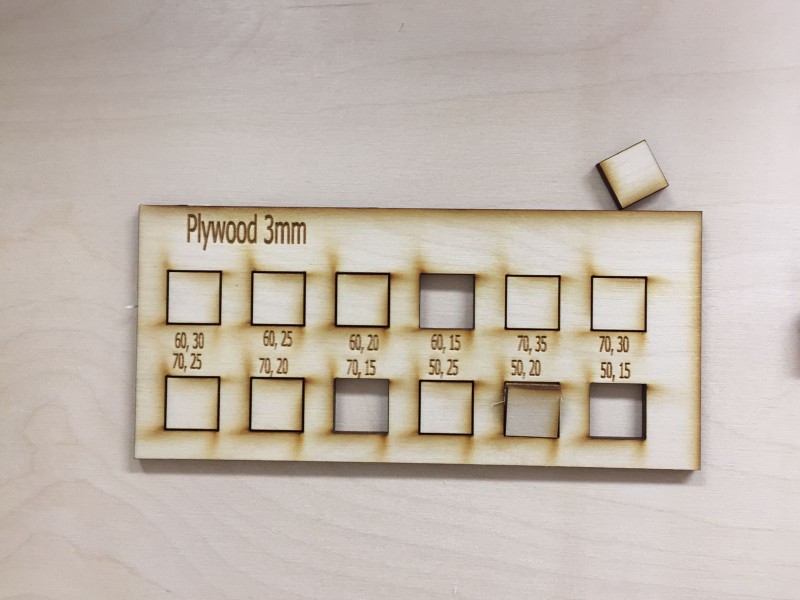
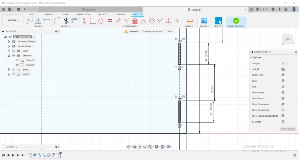
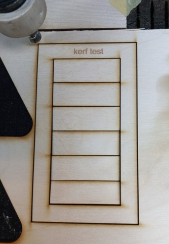
Then with each power and speed there is the laser beam diameter, which we divide over 2 and call it "kerf". so to calculate the kerf value we tried rectangles with different width all above 20mm and then measured their width after cutting so that the one having exactly 20mm width will tell us the kerf's value which in our case was 0.25mm
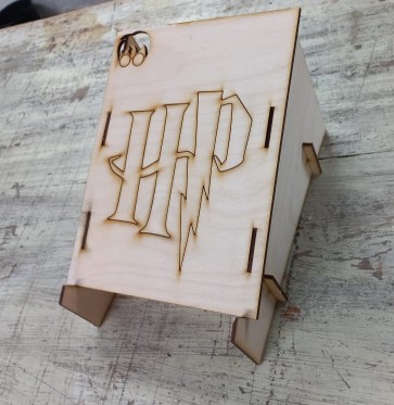
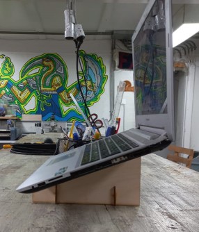
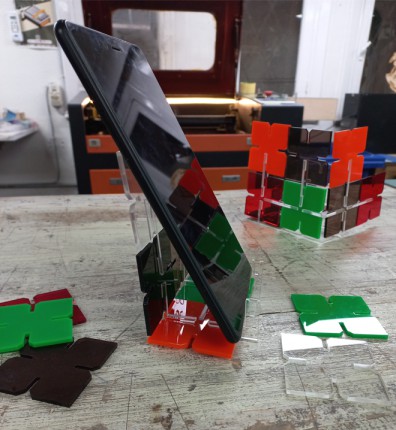
After that each of us had to design a parametric laptop stand, try chractrizing a material, and try 2 joints. in the following I will be illustarting how I designed and made my laptop stand using parametric design technique. Here how it looked like at the end.
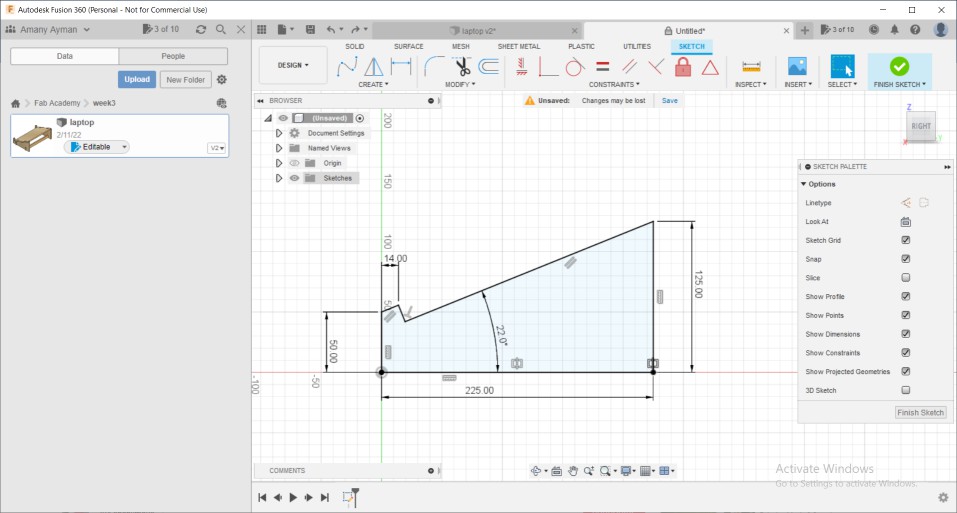
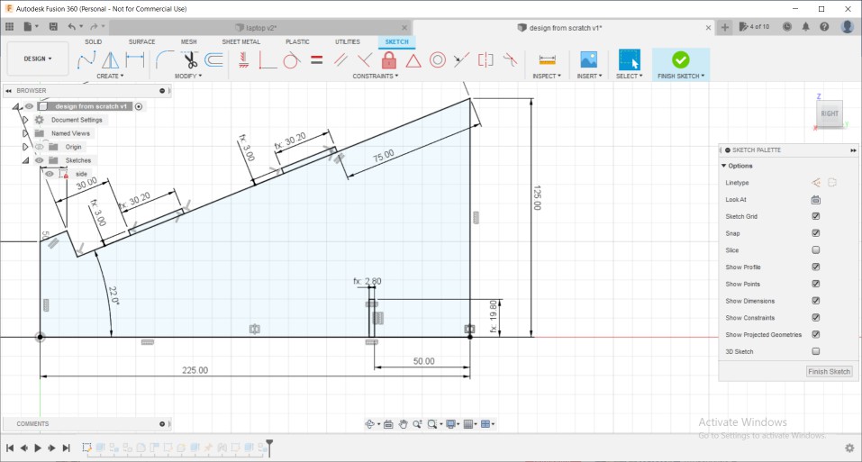
I started with the side sketch based on another laptop holder I found in a youtube tutorial.
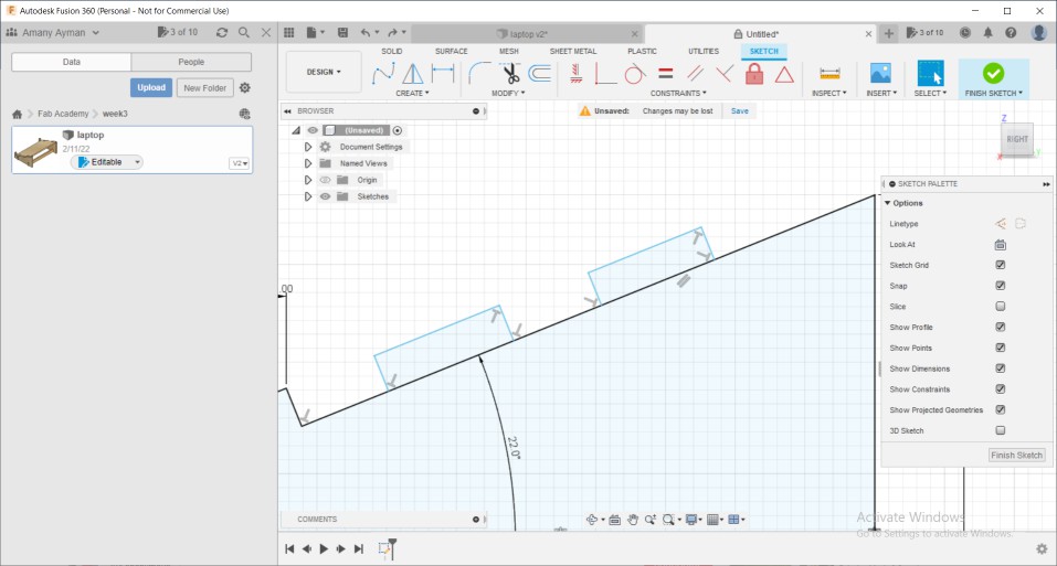
Then unlike the way the tutorial used - combine then cut as it will limit the slot dimension to only the thickness of the material not the kerf as well- Henece, I added tabs using line tool
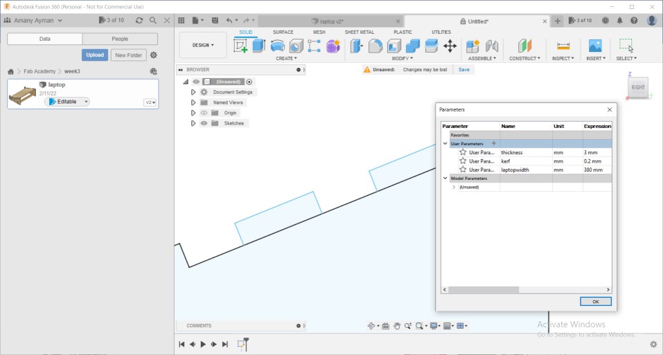
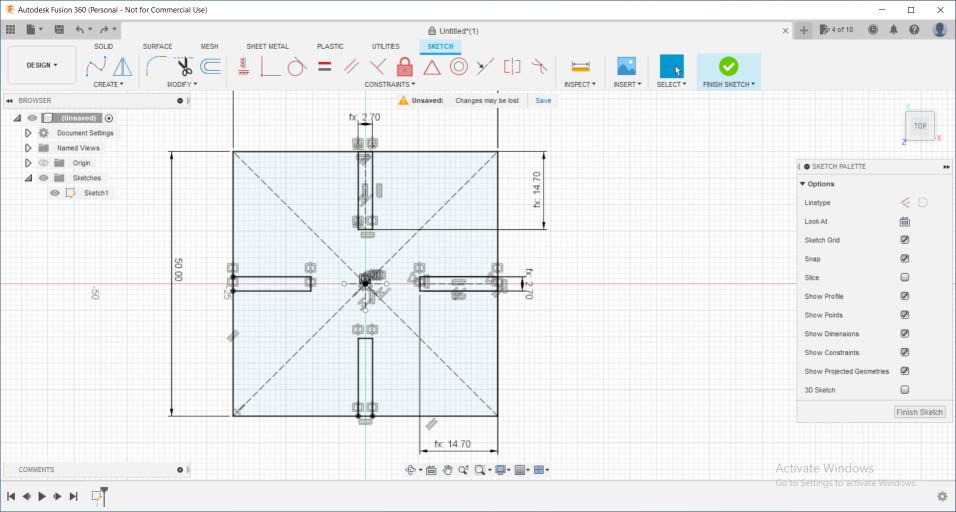
Then, added parameters to use in my sketch
then, setting tabs dimensions on the material thickness and kerf value
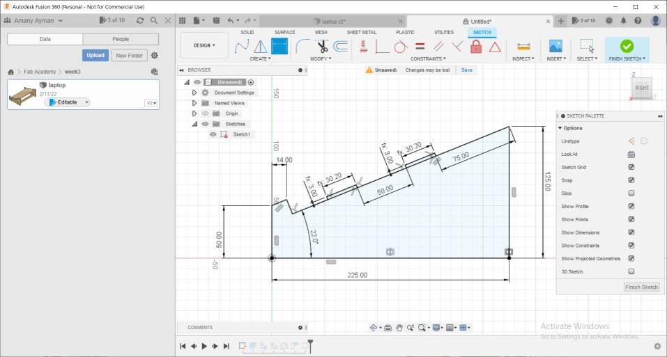
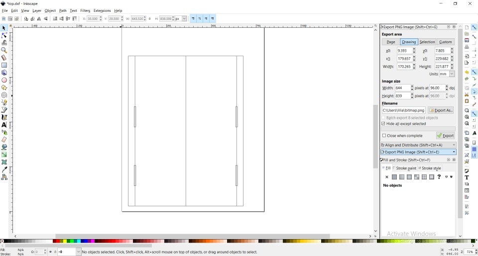
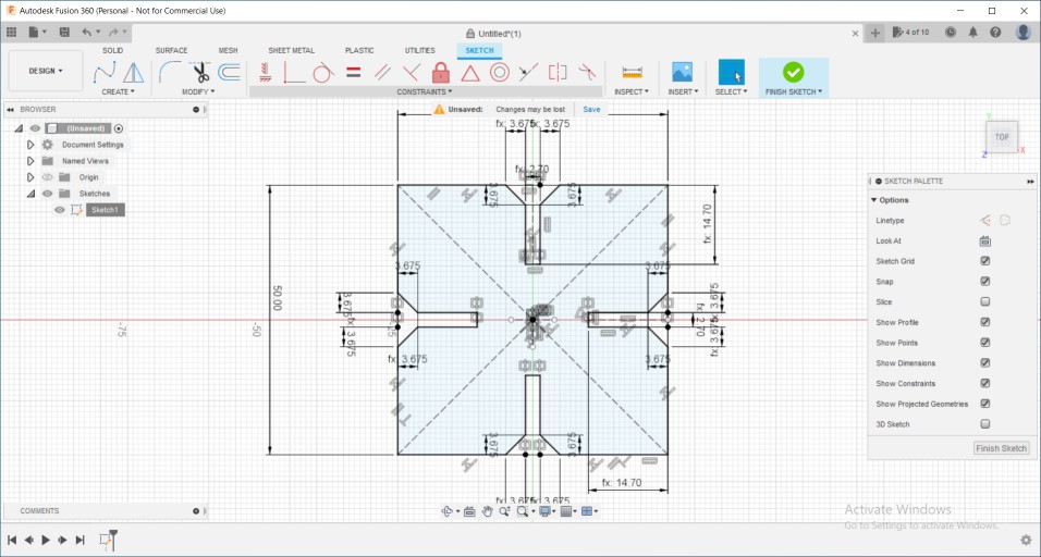
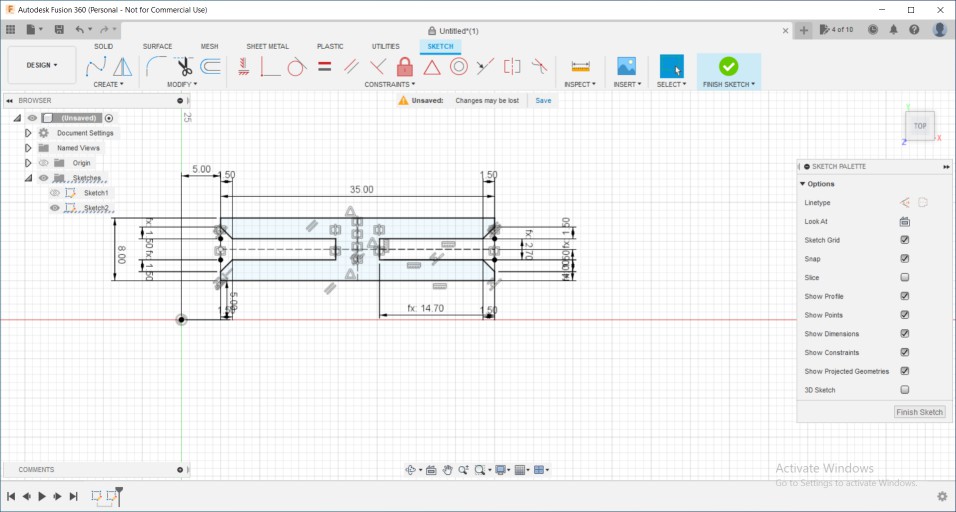
Now the the side is done and fully-defines, started drawing the top component with slots, as the laser beam will make it wider than wanted I started subtracting the kerf value from its dimensions
As only 2 parts won't be stable, I added slots on the side for supporting components.
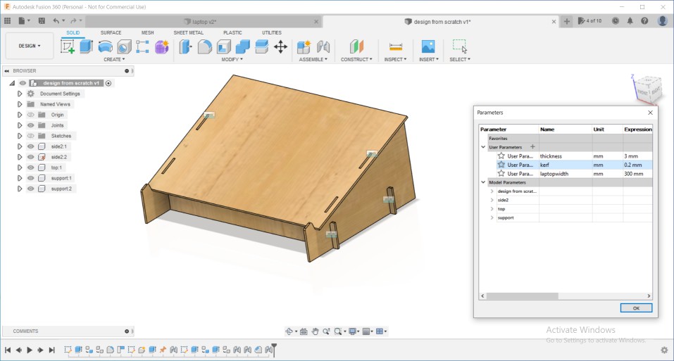
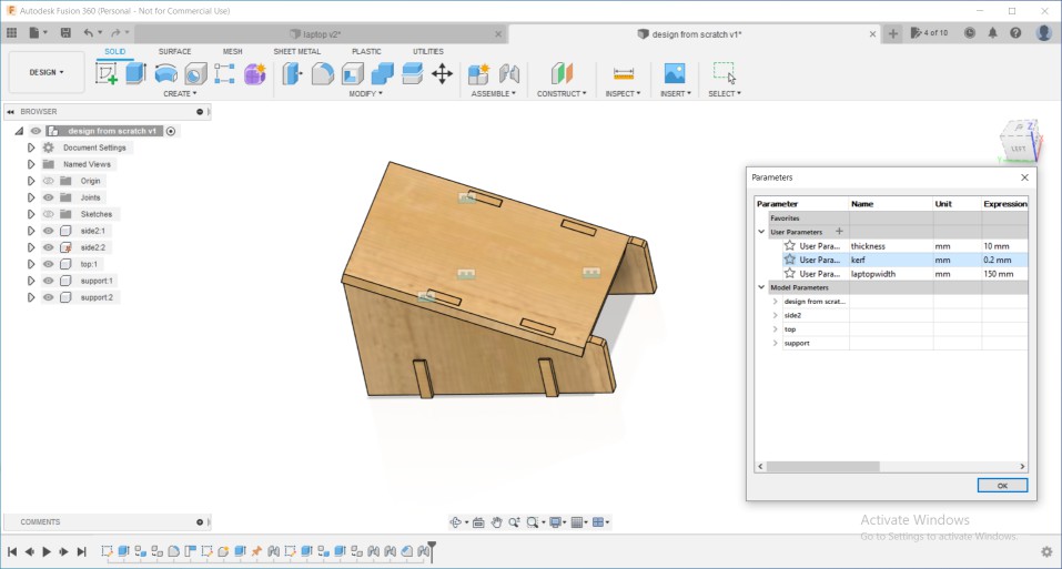
Then extruded all sketches making the extrude amount with the thickness parameter. After assemblying with rigid joints, now trying to change parameters to make sure everything is going as expected.
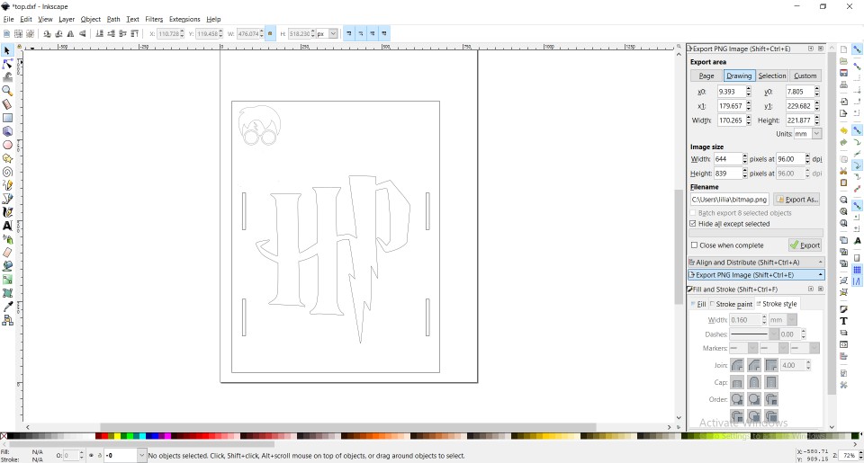
Finally exported the sketches into DXFs and opened Inkscape to add harry potter logo from pictures I found online.
Here is the final design after tracing logos and adding them to top component design
I didn't want it to be too big so I made it's width around 17cm, It didn't cover the whole laptop's base but it held it still. but its size where more suitable with the notebook though, maybe I went too much scaling it down :D
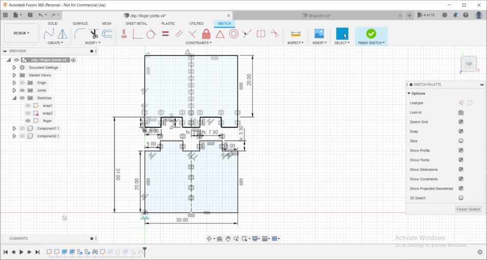
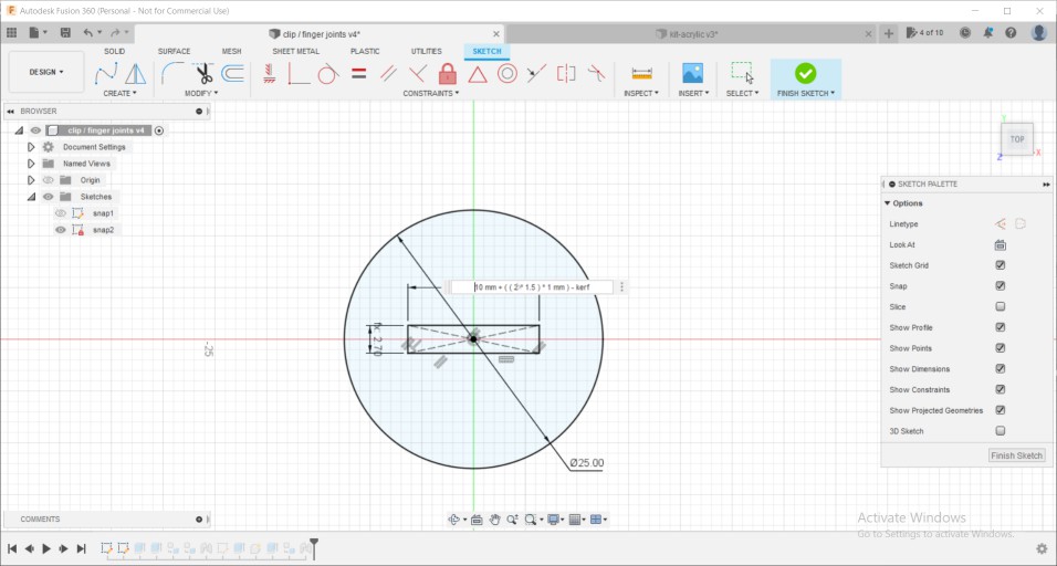
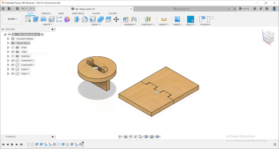
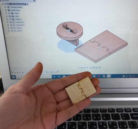
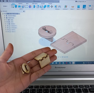
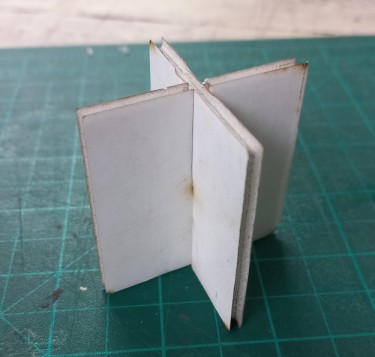
The joints assigned to me were snap and finger joint. After maching the laptop's stand they were a bit easy to make as it's almost the same process. In the finger joint I made the 2 parts into the same sketch to safe the time looking into dimensions back and forth between 2 sketches. But the snap joint was okay.
Here how they looked like after extruding and assembly.
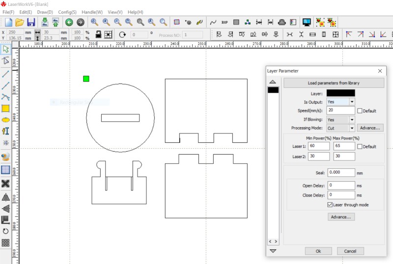
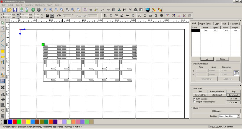
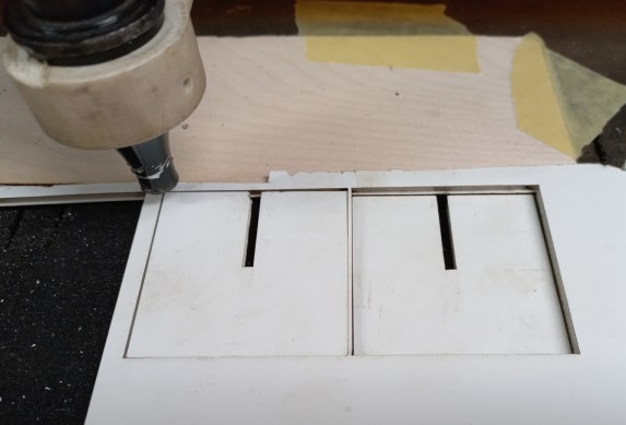
I wish that I could send fusion files to the laser cutter as is but I go through a process to prepare them for cutting. 1st thing is to export sketches as DXF then open them on a laser cutting software. we use one called " laser works" in it, you can specify the power and speed you want to cut or even change cutting mode into scanning or engraving.
I felt happy at the end with each tic sound when the parts sanp together, It's a great feeling to have in your hand what you designed on your laptop, even through assembly and animating joints, it's always feels different and more exciting.
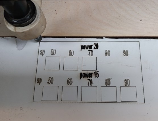
Regarding Characterization, I choose to test 3mm foam. So, tried random powers and speeds till I found a proper one which was speed: 50 mm/s and power: 20%
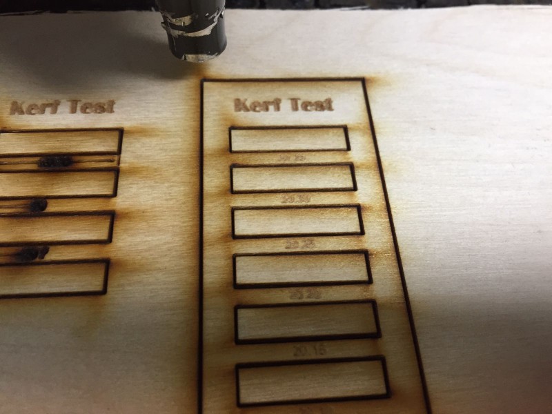
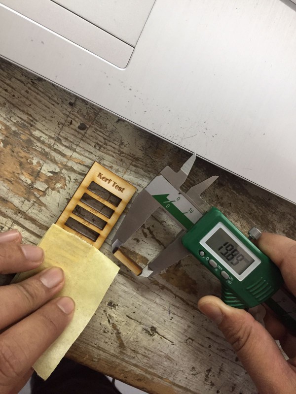
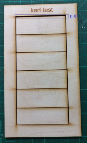
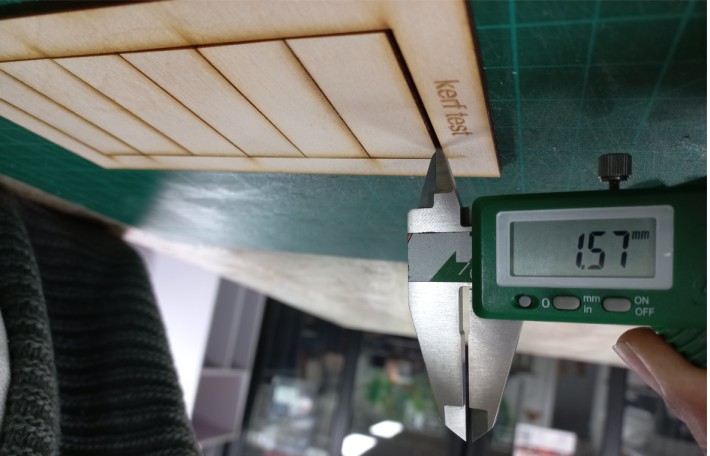
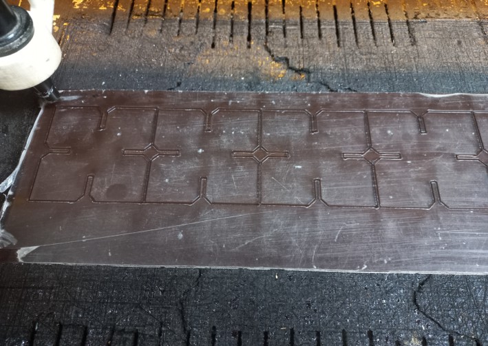
The last thing in the group assignment was to measure the kerf, we already did it togeether as I mentioned above, put our local instructor Kamel recommended that each of us makes a test to fully understant how it works. So, mine was to make multiple lines then measure the gap and divide it over the number of lines to get the kerf value. after laser cutting the Caliper showed the gap to be 1.51mm and there were 7 lines so dividing 1.57/7= 0.22mm which is the kerf value.
 And now, The assignment!
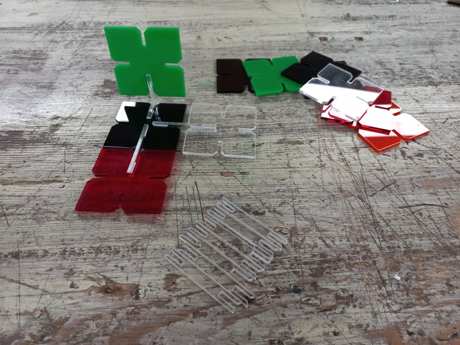
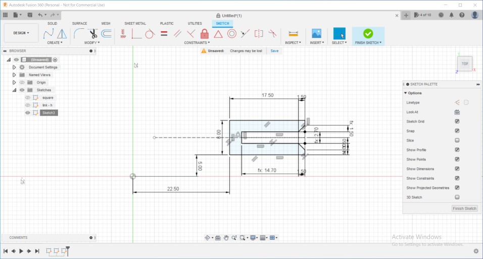
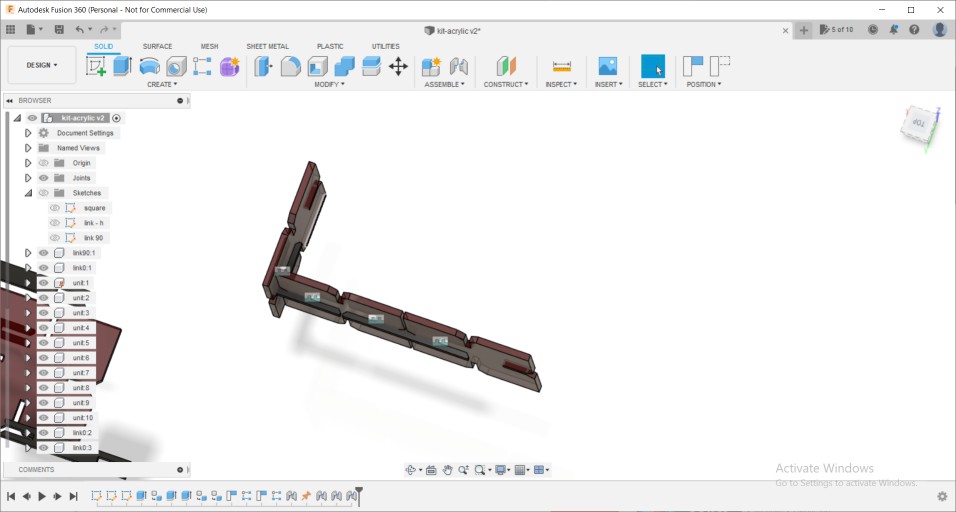
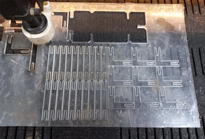
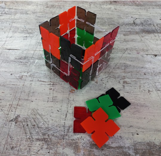
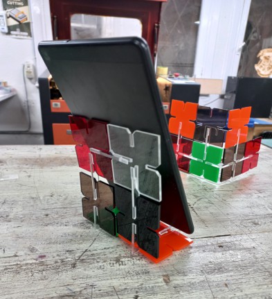
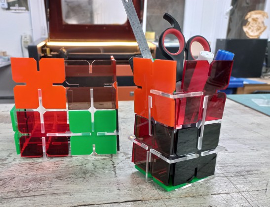
I often look for inspiration in Pinterest and find pretty cool ideas. so the original design I found was this one. I liked the different colours and how neat it looked. So, I used the main square block and design 2 extra parts to help with joints. Here is how it looked at the end.
Started off by sketching the square then added parameters to apply on the slots i will use.
Then used parameters into making functions in the dimensions then added chamfers to the edges, and the first unit is done
Almost using the same technique made the 2nd unit
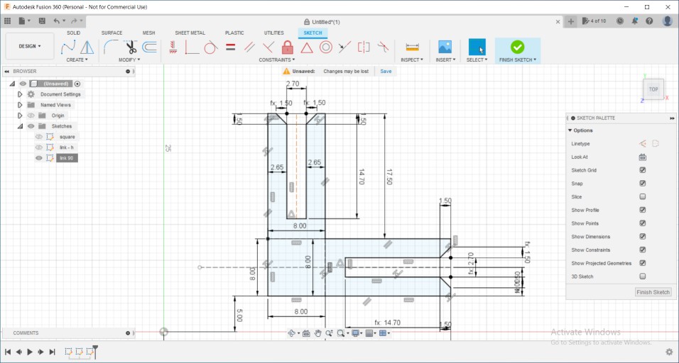
Then copid the last part and used only a half and pasted it to make a 90 degree link
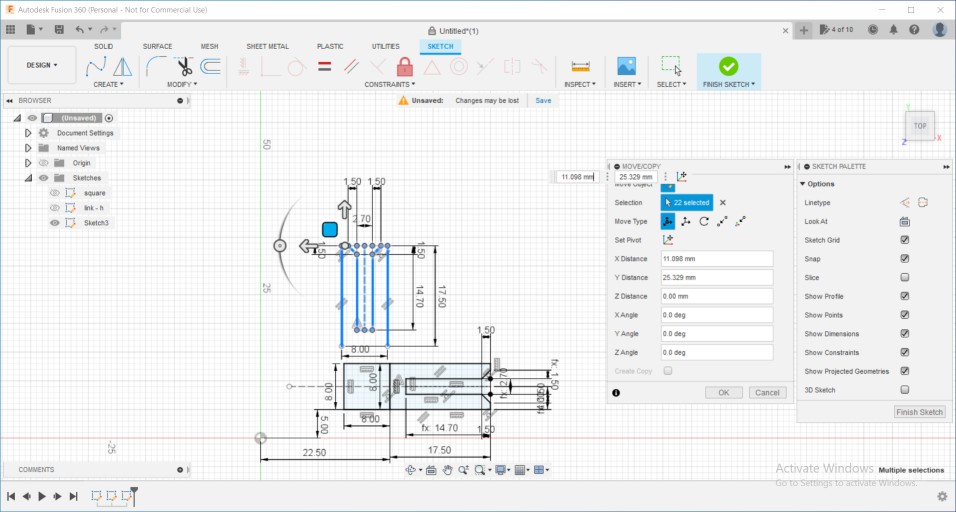
After adding some dimensions and constrains it's now fully-defined and so the 3 units are done and ready to be extruded.
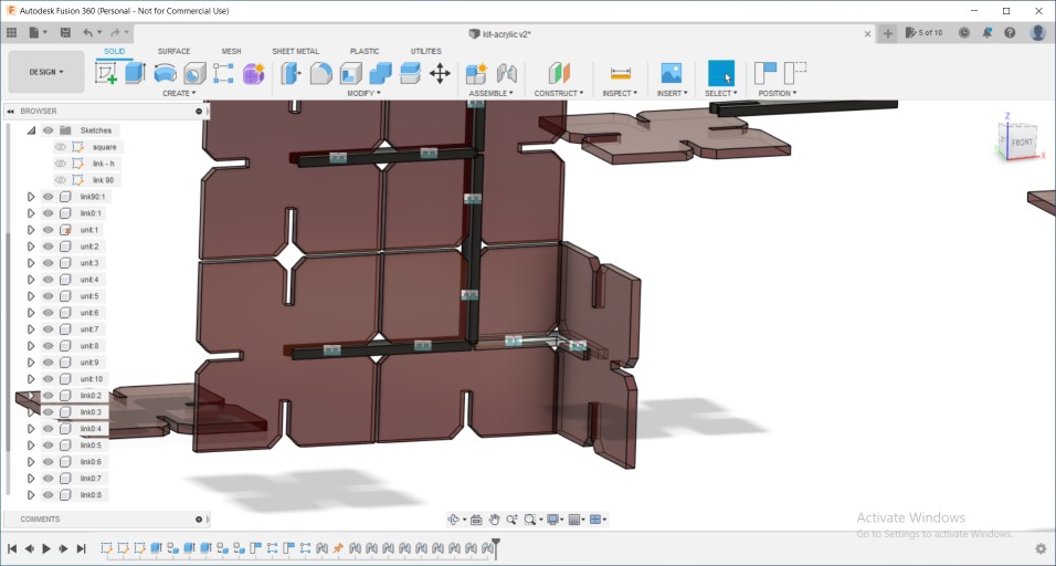
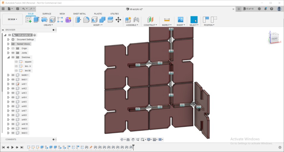
I wanted to multiply them many times to try different ways in construction, and to avoid copying and pasting many times did rectangular pattern
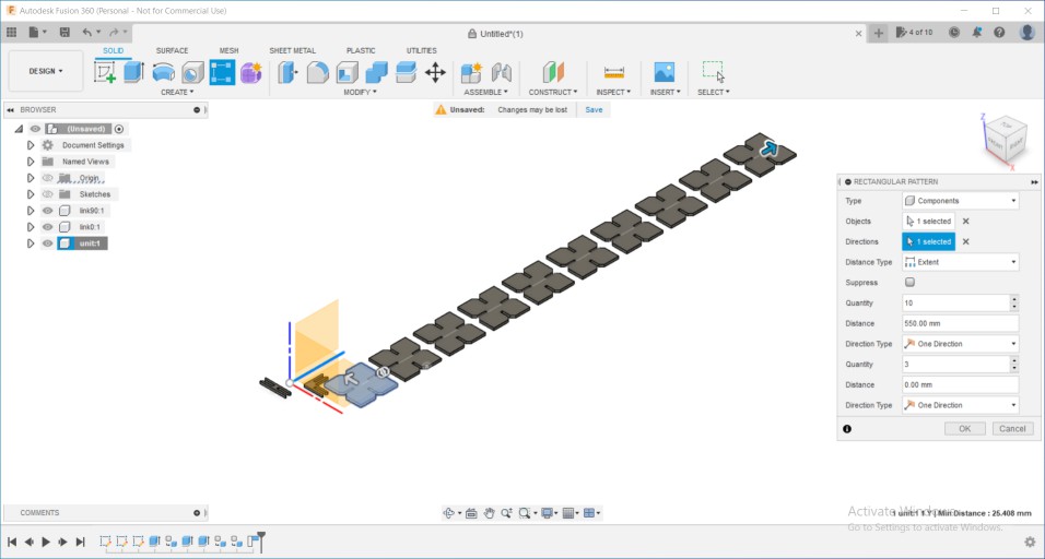
While assemblying them found out some mistakes in the design dimensions and that's where I always find the assembly very helpful to me.
Aaandd, finally it's all good now. so from sketches > right click > save as DXF and opened them on laser works like mentioned above.
Thanks to omar who is also a student in Fab Academy, his task in the group assignment was to characterize acrylic power and speed, so by the time I started my individual assignment he knew alot about acrylic cutting settings, So I asked him the final conclusions that he reached and started cutting right away.
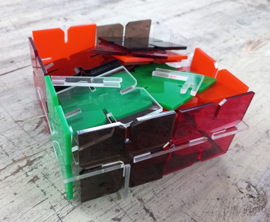
The original design was made out of many colours and I liked that so I made the same, but used transparent acrylic in the 0 and 90 degrees joints so it gives the feeling that the acrylic units are floating by themselves in mid-air :D I am really happy with how it came out and had fun while trying different shapes, and after I was done I de-assembled them and put the pieces in the box I made from the kit itself.
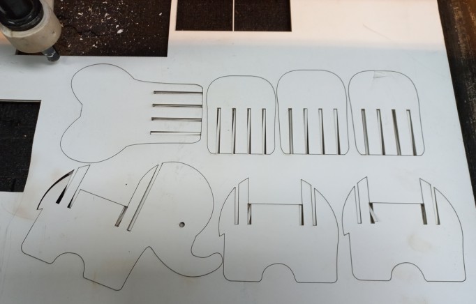
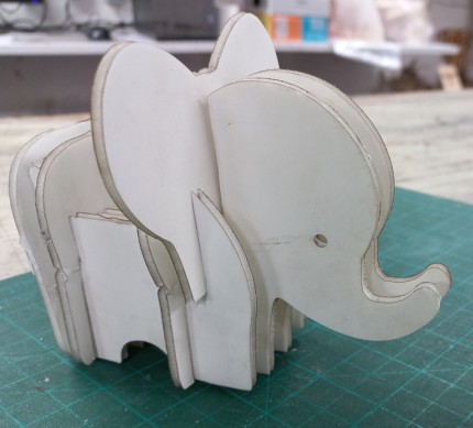
I also wanted to try other materials. As I already started with 3mm foam in the group assignment I tried making a simple joint then tried an design I found on 3axis.co which is a website that has many open-source laser cut designs.
The design was orginally a bit big in dimensions so I edited the slots and turned its width into only 2.5mm so that the foam can be press-fitted properly. As the foam is a soft material unlike plywood or acrylic, it was so easy to assemble.
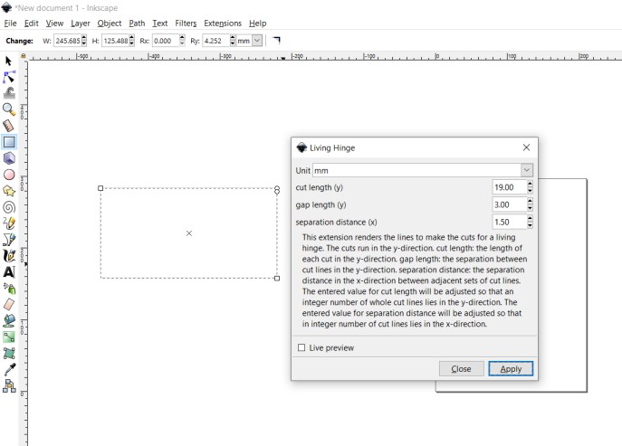
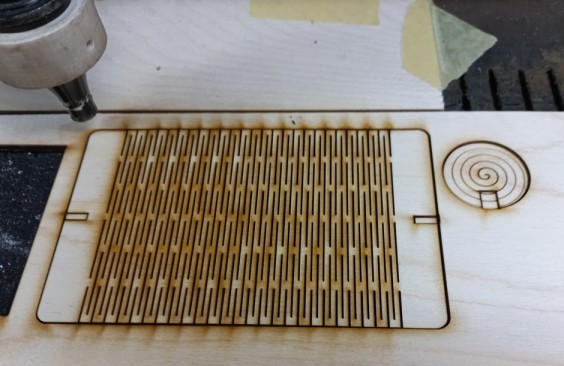
Finally, I was excited about the living hinge technique and wanted to test one. Instead of designing it myself, I found that Inkscape has an extension that generates living hinge you can download it from here. after downloading the source file, just copy .py and .inx files and paste them in the extensions file in inkscape program files in C. After successfully installing the tool, open Inkscape and you can find it in the menu bar > extensions > Render > Living hinge. So I draw a rectangle and generated a living hinge in it.
I made slots on both sides so I could close them together using a 2nd piece. I am thinking it will mostly be like a tiny bag that I will put my earings in.
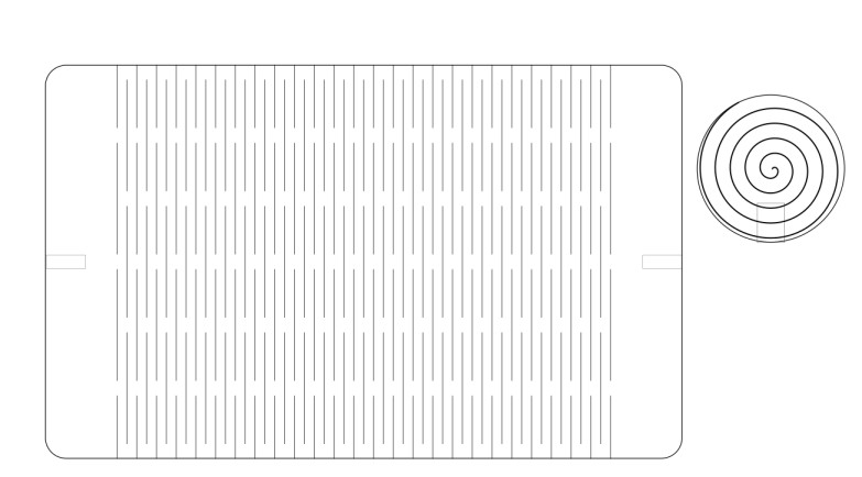
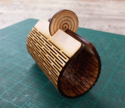
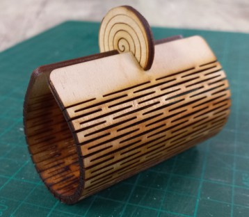
So I added a 2nd unit that will lock the bag and draw on it a spiral as it looks cool while being fabricated on the laser cutter, I am sharing a video of it too. :D after 1 face was done on the laser cutter, I flipped it around so the spiral appears on both sides. After Assembly I realised that I needed 2 different slots as I can't bend the flex into a 90 degree joint without it to break so adjusted the locking unit to have 2 slots. Also, At the end I realised that it needed sides to block what's in it from falling off, will take that into consideration next time :D But all in all I like it.
 Now comes Vinyl cutting!
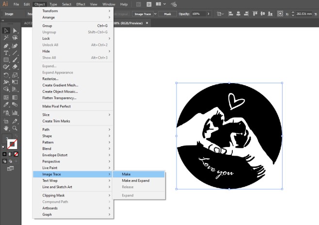
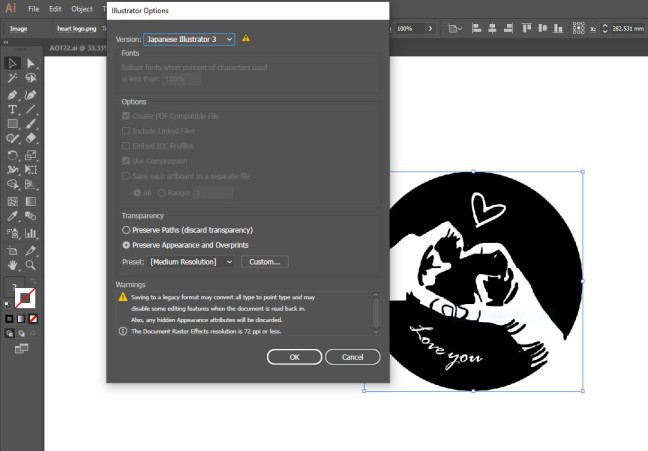
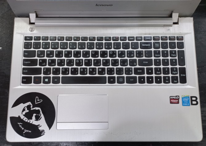
I already had a design ready since CAD week, as I designed a logo on GIMP which is a Raster based, But to be able to cut it I needed to convert it into vector, made that through tracing tool in Illustrator then exported the file into .ai extension but the next software that deals directly with the inyl cutter needs a specific version so saved it as japanese illustrator 3
Then opened cut studio and adjusted the design dimensions through properties. then fromm file > cutting and started cutting. It is really straightforward operation.
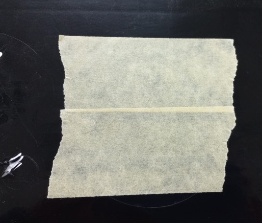
It was done in less than 2 mins. after that I needed to put it on my laptop but there were many tiny stickers and letters in the design, So used a trick were we but a duct tape on it then remove it from its original sheet then put on the laptop and got rid of the duct tape.
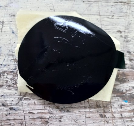
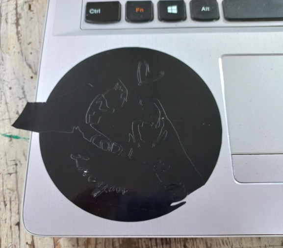
Then, All I had to do was carefully remove the pieces I didn't want, and finally it was done ^^
 Source files:
Individual Assignment files
Construction kit Fusion 360 fileLaptop stand Fusion 360 file
square unit DXF file
link 1 unit DXF file
link 2 unit DXF file
Heart logo - Vinyl cutting
Elephant CDR file
Living hinge SVG file
Group Assignment files
Joints Fusion 360 filefingers joint DXF file
snap unit 1 DXF file
snap unit 2 DXF file
kerf test DXF file
Speed/power test RLD file