


Here is my Hero-shot of the week! I never had that chance and the time to make all those tests to characterize a 3D printer and it surely helped me a lot to design for 3D printing and know all those joints and techniques. And let's not forget about 3D scanning too, it's very interesting to do reverse engineering of an object and bring it from real life into computer softwares were we can manipulate it however we liked and were there are limitless possibilities of how can it be.
Let's start first with the group assignment
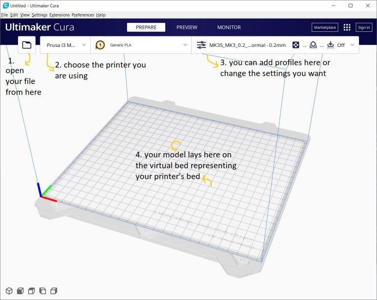
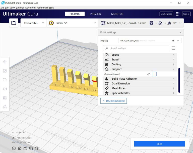
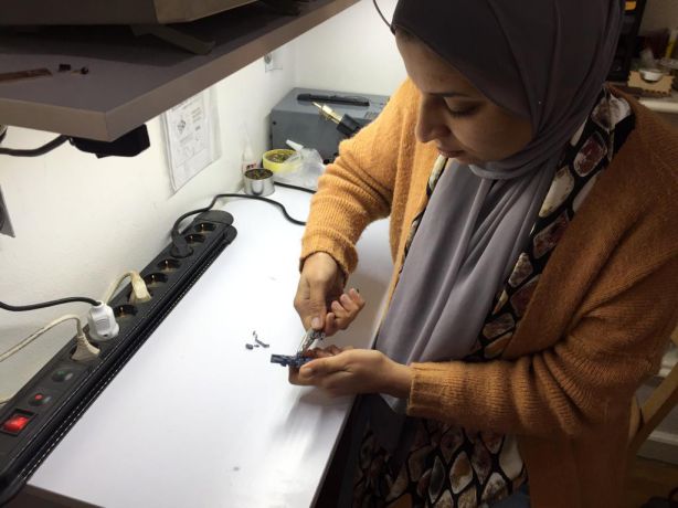
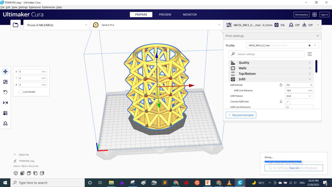
We started with characterizing the Prusa(s) we have in Fab Lab Egypt, They vary between MK2 and MK3 models. So we started characterizing them. So, we first dowloaded the characterization tests Then each or us "Omar, Moiz, Omar and me" had to slice 2 different tests and print them. I worked with clearance and angles. So, After downloading the STLs I opened Ultimaker Cura software to slice them. you can download Cura from here. Here is the GUI of the software
Then After opening the STL I added support blockers in the numbers section and the gap between the rod and the pieces so that the printer doesn't build any material inside.
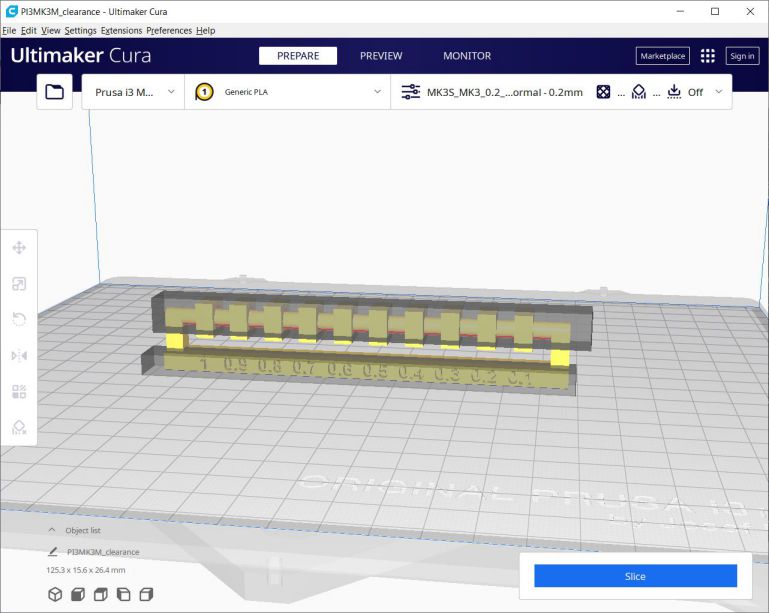
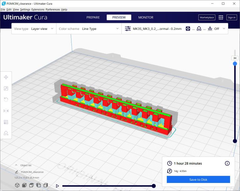
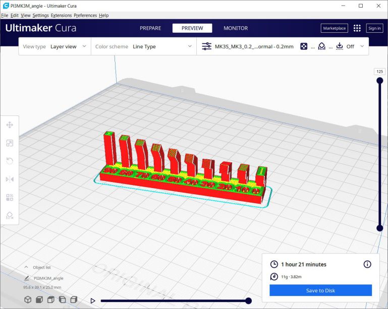
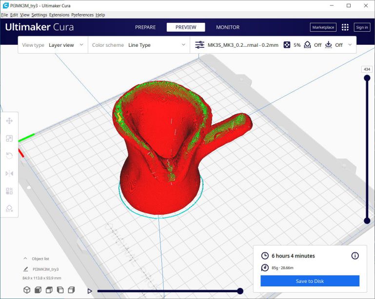
After clicking Slice button down on the right the softwares generates the G-Code which appears in the "Preview" window. Here the model appears in layers depending on the layer height we set it to be. and using the slider on the right we can see each layer from the first up to the last one. Here is how the model looked.
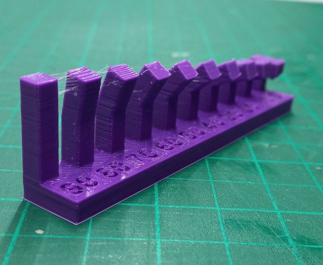
The next STL assigned to me was angles, and we didn't need and supports so we could know at which angle it will fail, so here is before and after slicing.
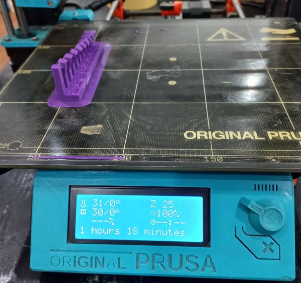
After G-codes are ready, I copied them into the SD card of the printer and pasted them. Then Printing time!
That was the angles, As for the clearance test I needed to remove the supports first to check it's movement, so here is me doing that in the next photo :D
 Conclusion
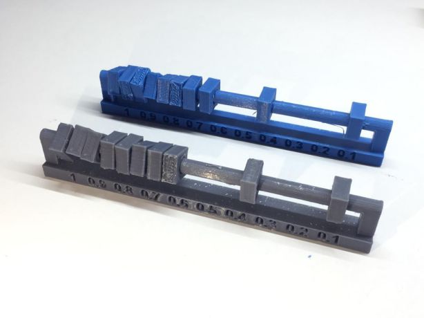
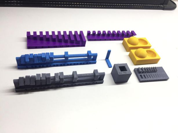
As for the rest of the tests you can view Omar, Moiz and Omar documentations as well :D. But finally we made all the tests, and what we came up with was:
- Best clearance starts from 0.2mm as the 0.1mm gap didn't move at all.
The angles were all okay without support except the 0 degree overhange which made 90 degrees sharp.
- All bridging within 2cm worked perfectly.
- The difference in the quality between 0.1mm and 0.2mm was pretty obvious in the curved sphere. the smaller the layer height the better but it also increases time of printing.
- Anisotropy deeply affects the strength of the part depending on the direction of the force applied, so it eventually broke at the section which was built with smaller cross-sectional area.
- The thinnest lines and holes made were 0.4mm which is the diameter of the nozzle we use.
 Now comes the 3D scanning part
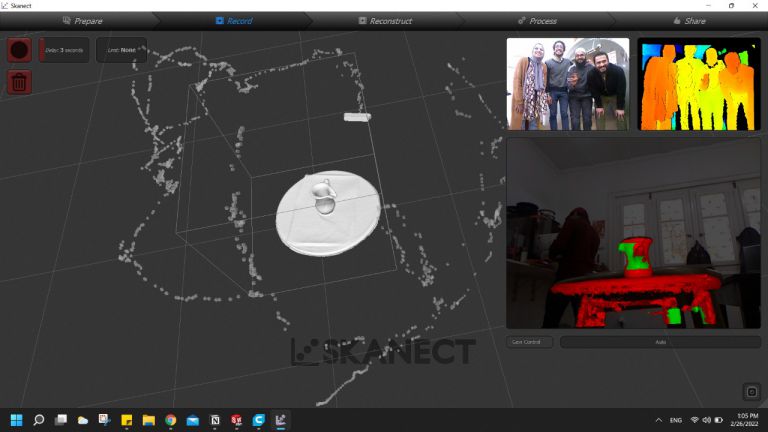
We used KINECT which uses infrared lights and sensors to calculate the field of depth of and around an object and through a wire it transfers those data to SKANECT software which we later get the STL from. To have a proper output we need to move 360 degrees around the part to scan all its faces and also move up and down so we decrease the chance of having holes in our STL. Here are some pictures of how the process went.
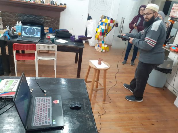
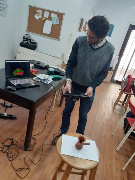
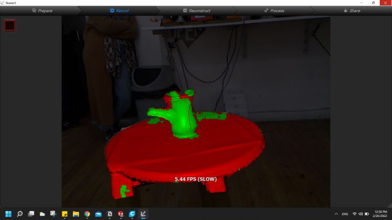
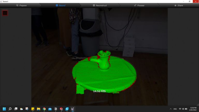
While moving around the part holding the KINECT, the software shows you the progress you are making - green means good - and you need to do the rotation between the positions very carefullybso it can relate between the past position and the new one, if moving too fast it will unfortunately break on software. Here are screenshots from SKANECT while scanning
After finshing all angles it's okay to move KINECT away from the object and then SKANECT will process the part and detect the path of the positions you took and generate a 3D model of the object.
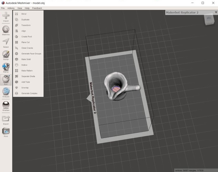
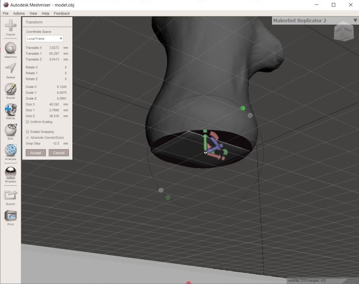
Then, Each of us had the STL and edit it individually on his lapotop using Meshmixer. So I opened Meshmixer and opened the STL, then 1st thing was to change the orientation as it was a bit inclined then separate the model from the base it was on from edit > split bodies
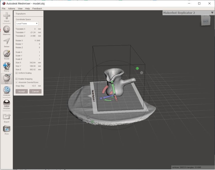
After that the hole missing from scanning appeared at the bottom so I needed to add material eather from a brush or the faster way was to add a shape like a cube from Meshmix button
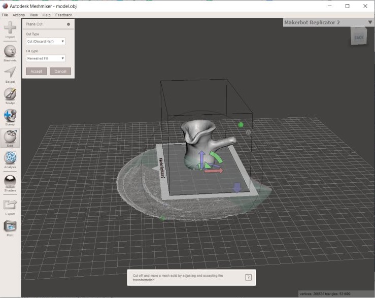
Then from File > Export I exported the model into an STL and opened it on Cura but it gave me an error. it appears that the cube i added wasn't joined with the base body.
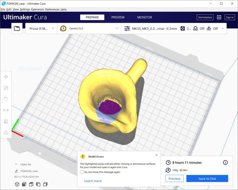
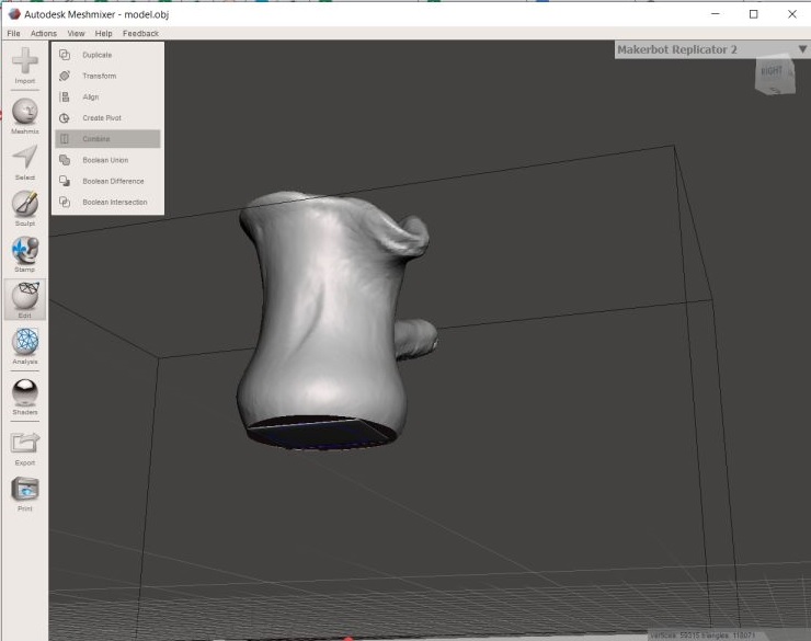
So, went back to Meshmix and searched for something to join or combine them, so selected all and a menu appeared so from which choose "combine" and exported again and it had no errors on Cura this time then sliced it and it was ready for printing!
 Aaaannnd now, The assignment!
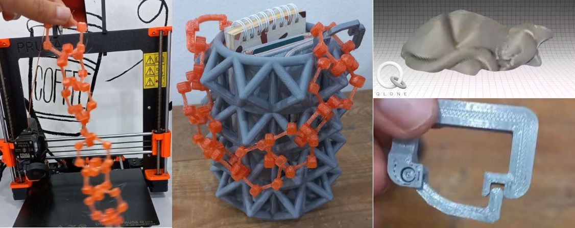
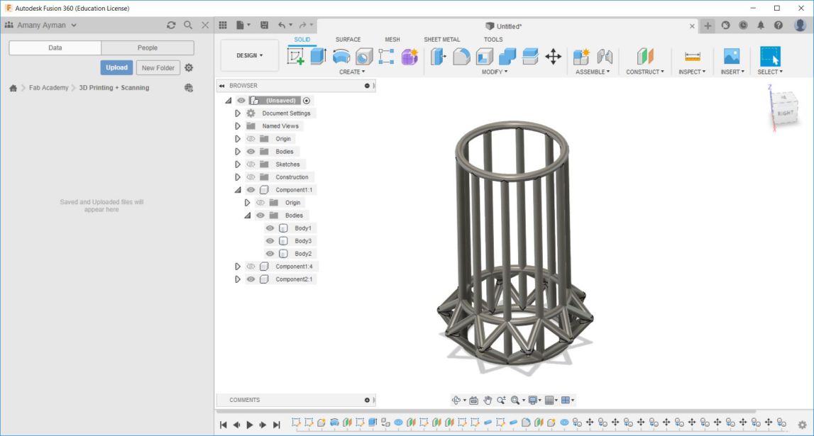
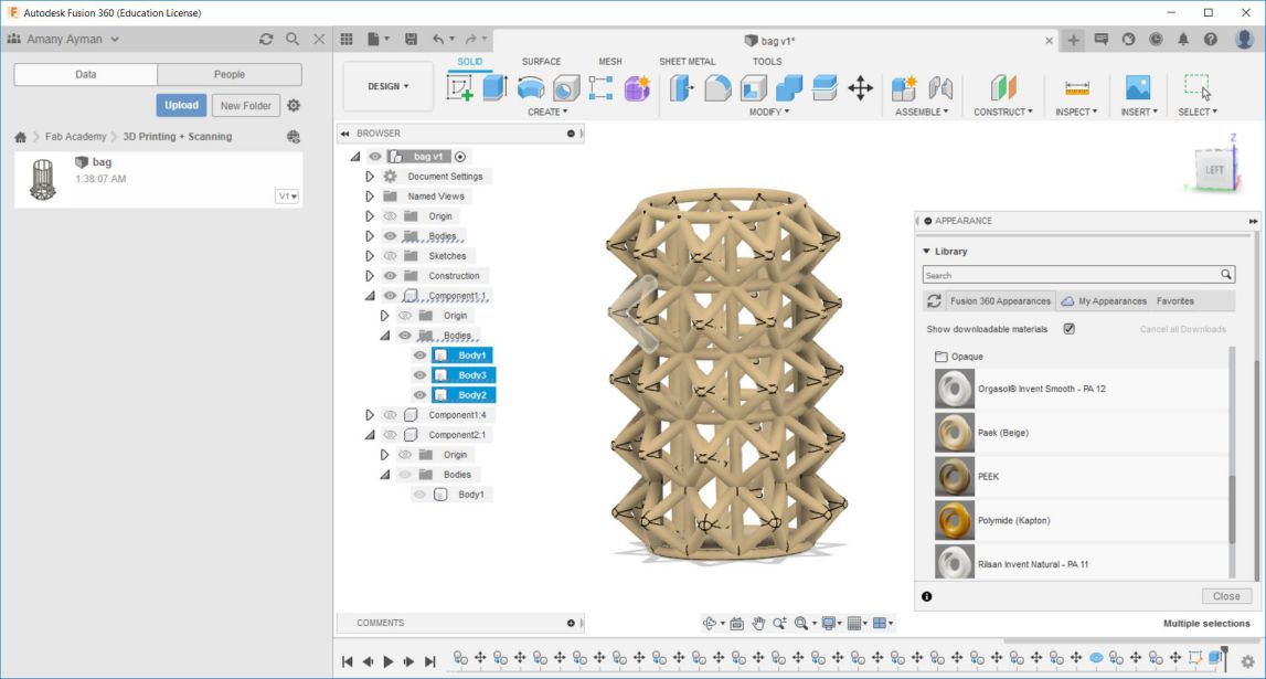
I always use Pinterest for inspiration on tasks and assignments that need creativity and such so I found an interesting 3D printed bag! which contained 3 different parts having features that attracted my eye. As the main part wasn't easily done subtractively + the angles it has helped build it fully without needing any support. The second element was the chain, 3D printed chains always catched my attention but didn't try them before so I saw the chance of finally making one. Lastly, the lock hook that joins the 2 main body and the chain together which need to have a movable joint to open and close easily, so making that was also a new thing for me, I was so excited to start with it and see what will be its output. Which was this! I am very satisfied with each design as it turns out that all 3 of them are not easily done subtractively. :D
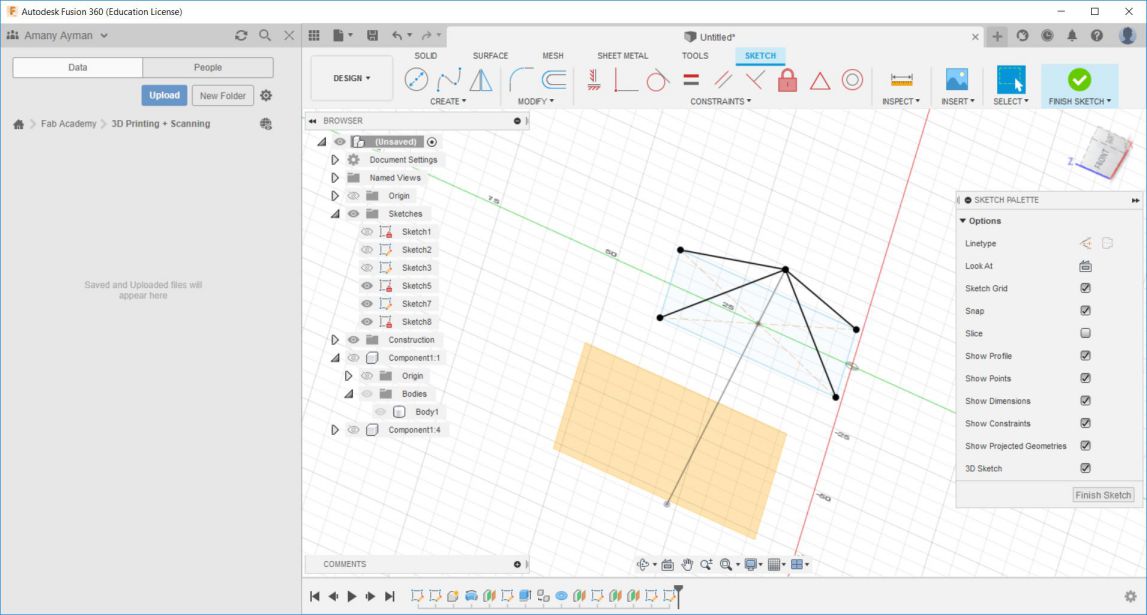
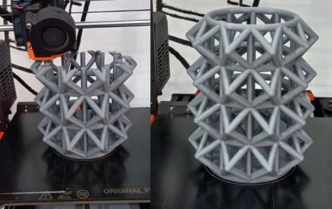
Here is How I made ItLet's start with the base part. I designed it using Fusion360, I won't mention all the tiny details of the software but you can go to my CAD week documentation if you want to know a basic knowledge of Fusion 360. First I start with a simple sketch of a circle and on a perpendicular plane I made another circle and using sweep I made a pipe, then copied it with a specific distance
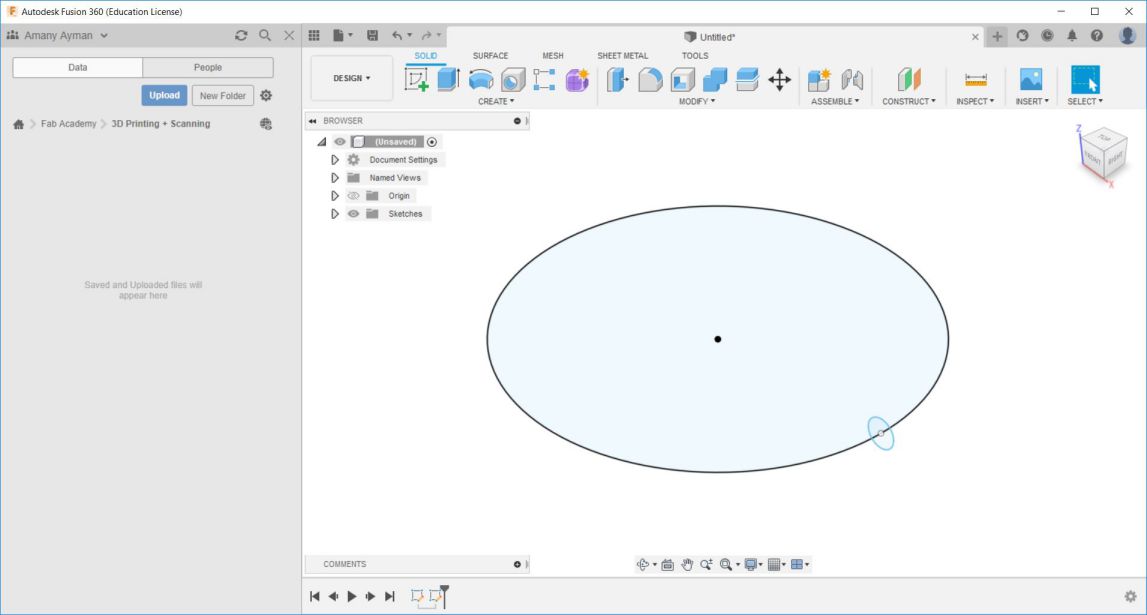
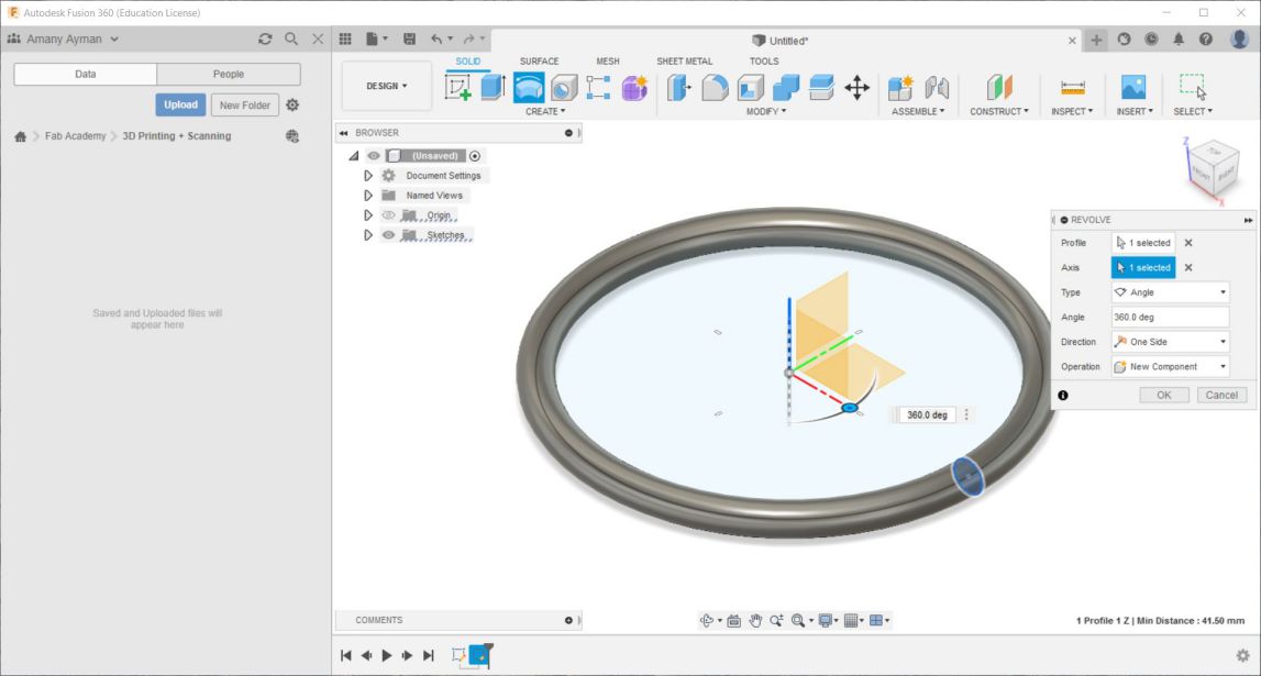
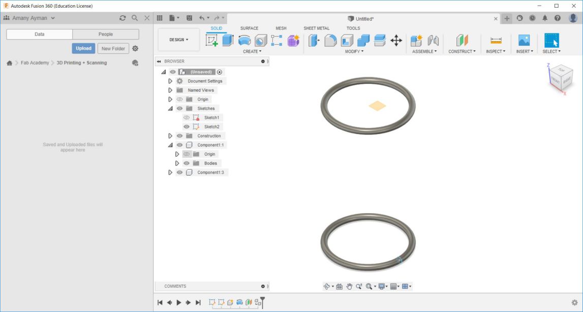
Then in another sketch made a circle and with a circular pattern made it around the pipe and using extrude connected the 2 pipes together.
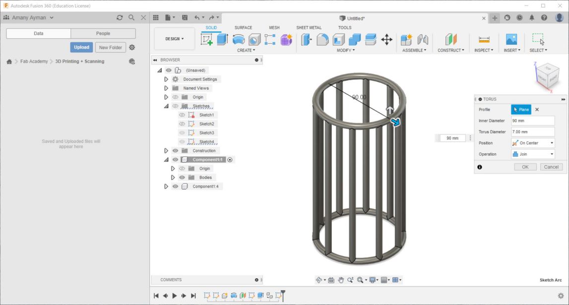
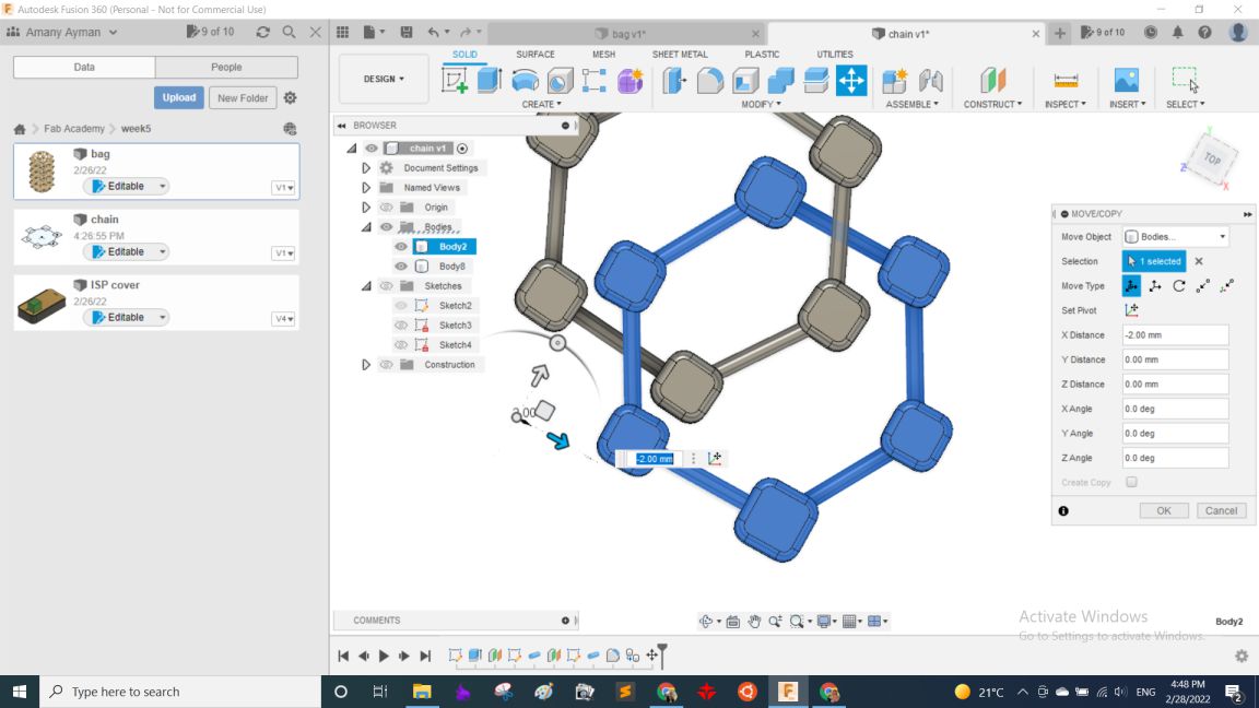
Then to be able to make links and nodes far away from the plane I was working on I needed to work on 3D. So from setting I enabled designing and sketching in 3D. Then started drawing lines and join them together to make the unit I will repeat all over the part. Then used pipe which creates a pipe following a selected path "from create menu" and choose the path to be those lines I just drew.
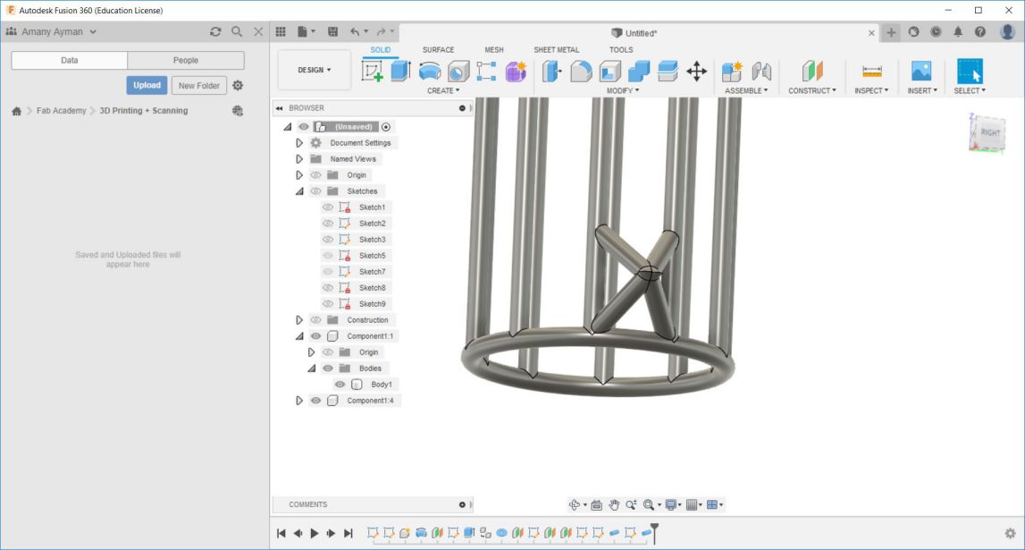
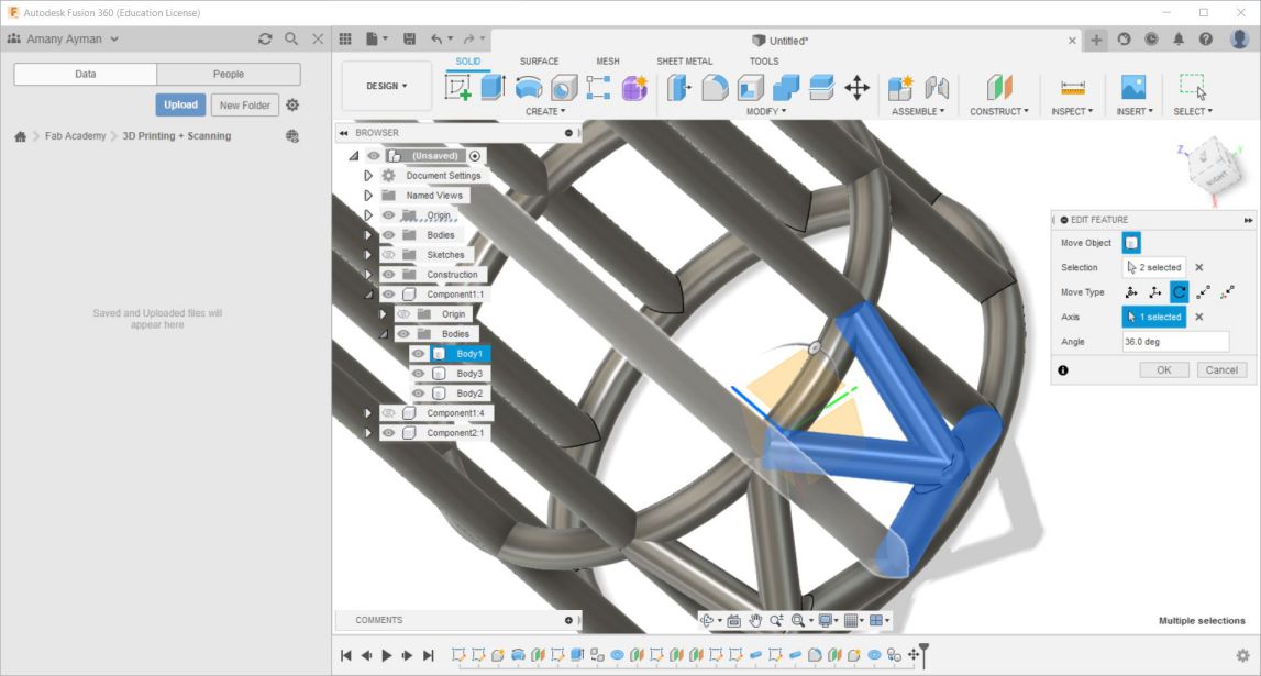
Then used fillet to remove sharp corners and then used circular pattern to make multiple copies with a degree 36 as I had 10 columns with divides the whole circle into 10 equal parts. then replicated it on the upper rows and used combine to make it 1 single body, and it was done. To have the STL file, right click on the body and click "save as mesh".
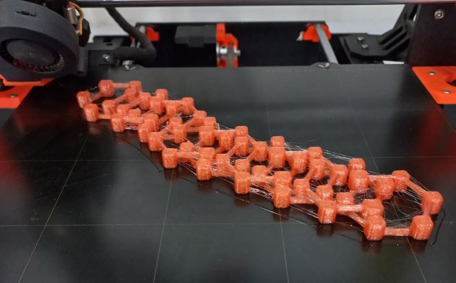
Secondly, the chain. It was a simple quick design but the main feature and the most important thing while making it was to making a difference in height between the links so that it can slip under each other which basically makes the chain. In this design I considered the bridging was up to 2cm so made the links shorter than 2cm so I can print it without needing supports.
So drawn a hexigonal and squares on its edges and then extruded them.
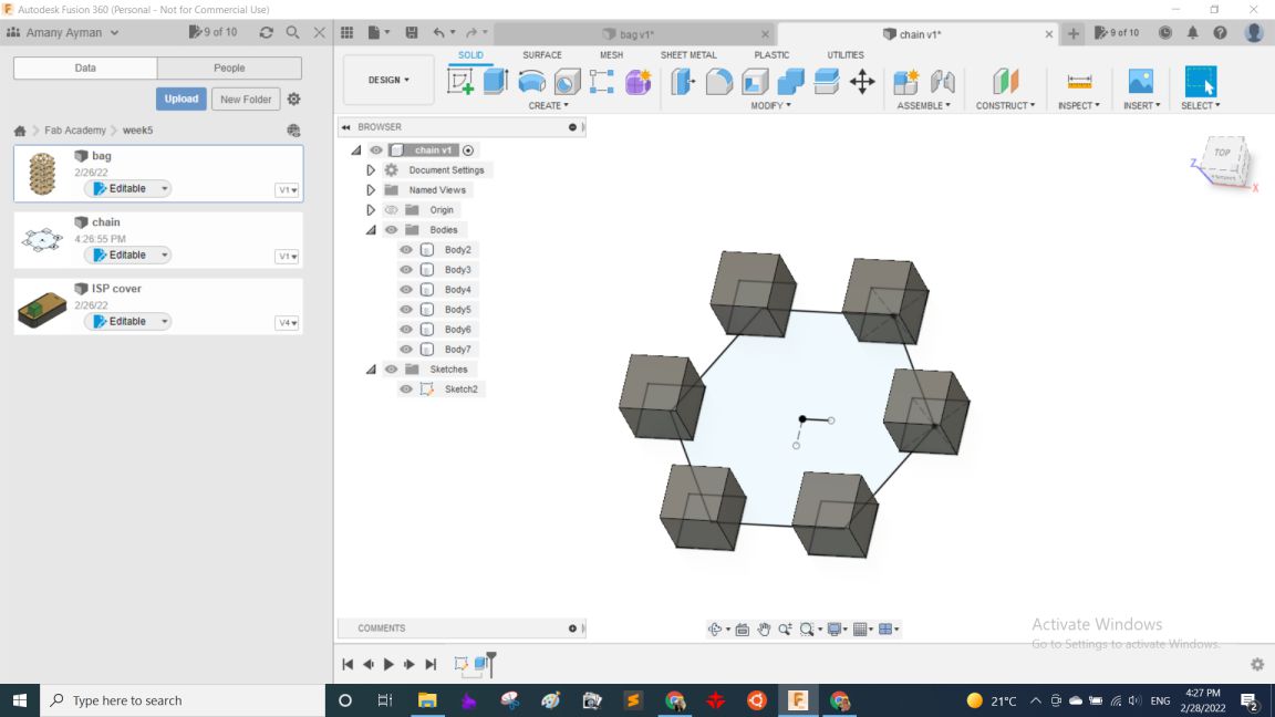
Then used different offest planes on different distances and projected the main sketch on each of them then from pipe made the connectingg links, and that's how I made the unit that built the chain.
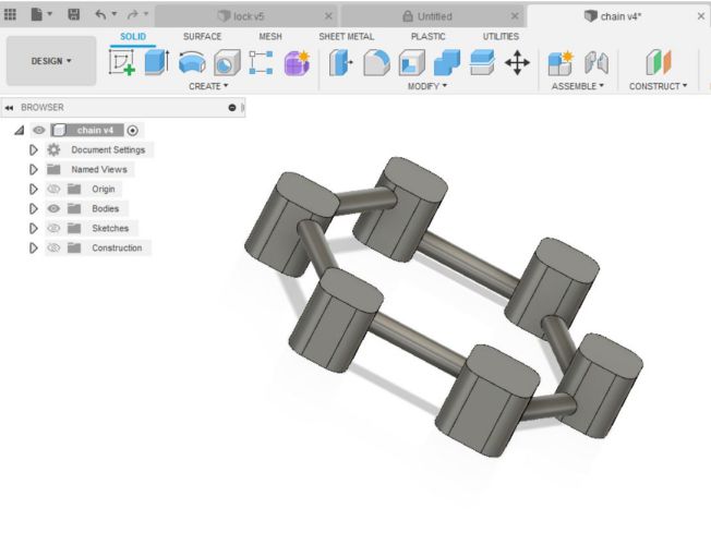
The rest was copying and pasting and moving the units under each other
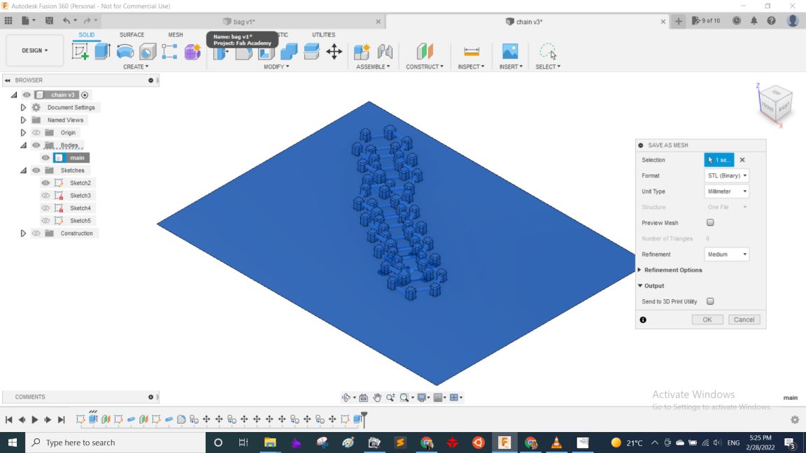
The final step was to export the file into STL, but here I thought that it may export the units separately from each other as they are all to the software different bodies that aren't connected! So I asked my colleages if they have any solution and Moiz had a wonderful idea, which was making a thin plane connecting them all together making them 1 body, And it worked! Million thanks, Moiz!
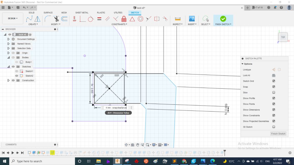
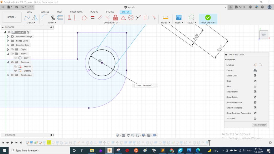
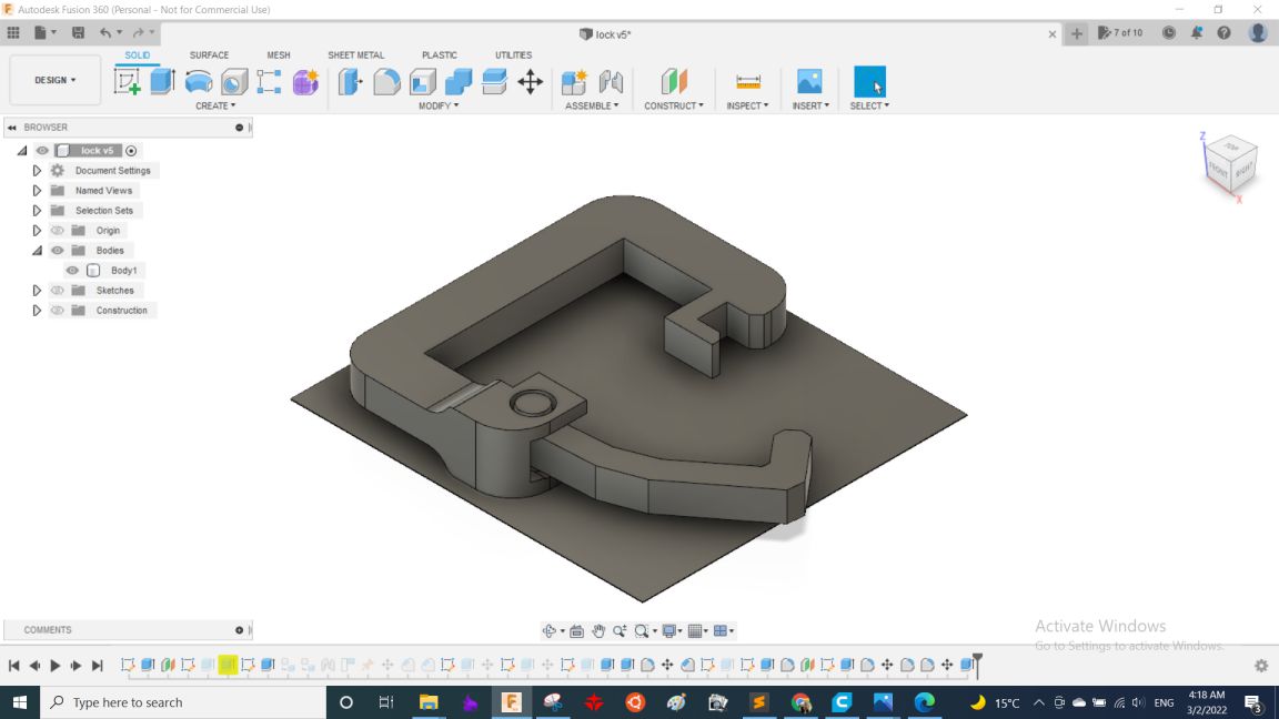
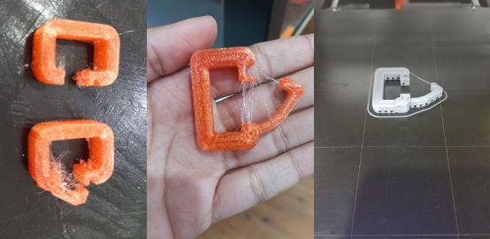
Lastly, the lock. It also had a simple idea but the important feature in it was clearance! as in moving joint it must be loose enough to move easily, and at the other hand to make it snap-fit to lock well, So I made a parametric design that had the clearance as a parameter to be able to change it easily while testing the proper values. it took around 3 or 4 iterations in printing to make it work and understand thst they needed to have different clearnce in the first place.
And with using extrude and the same trick from the last part the design was ready.
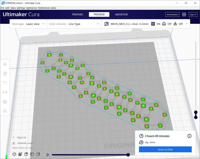
After designing comes Slicing. I opened Cura to start slicing, for the main part it didn't need supports but it had large dimensions which were 135*130*160mm. so, I decreased the infill down to 5% so it weighs less and also take less time in printing, So with 0.2mm layer height it took around 17 hrs and 180 grams.
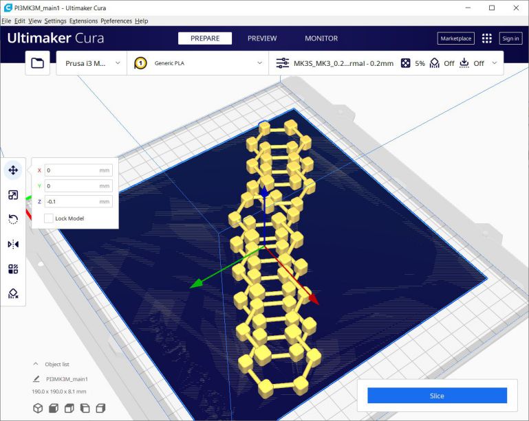
For both the chain and the lock hook with an extra 0.1mm plane to join the parts together, there is a simple trick to solve it which is to move the bodies down in the Z-axis in cura to -0.1mm as the following picture
Finally, after having the g-codes I started printing them. So, here are pictures while printing and after assembling them togther.
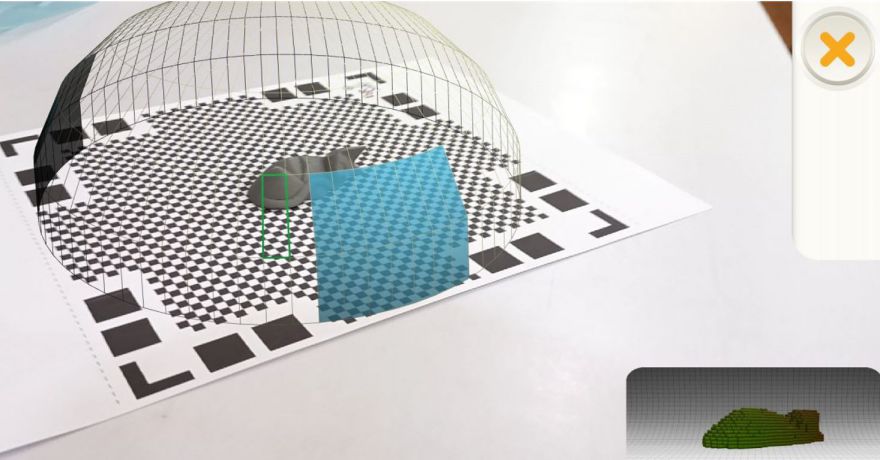
 3D Scanning
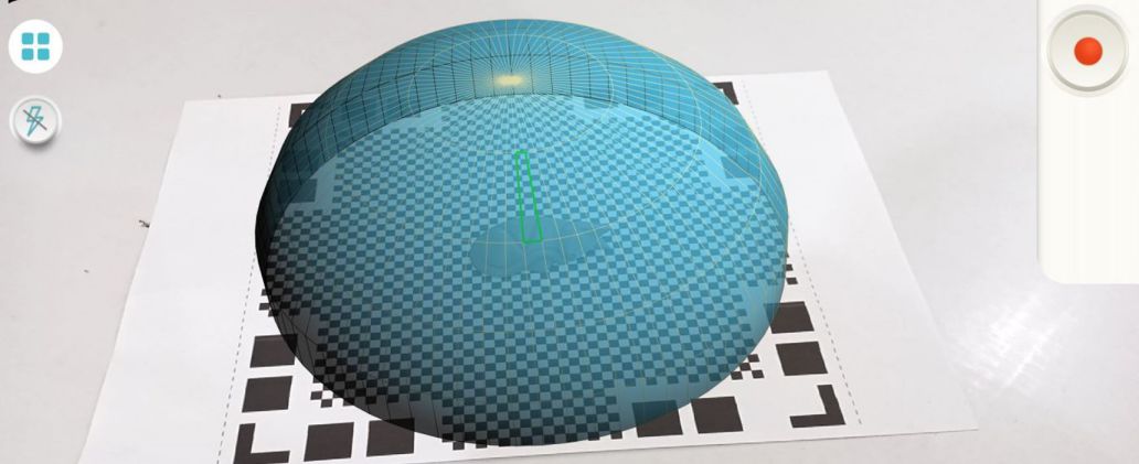
As for 3D scanning I used Qlone mobile application. It was very easy to use, just printed the paper that I put the model on. Then either I rotate around the object or rotate the paper with the object, then after 10 minutes it's done!
 Source files:
Individual Assignment files
bag Fusion 360 fileChain STL file
Lock STL file
Group Assignment files
Vase STL file