Computer Controlled Cutting
***GROUP ASSIGNMENT***
Learning outcomes
-Demonstrate and describe parametric 2D modeling processes.
-Identify and explain processes involved in using the laser cutter.
-Develop, evaluate and construct the parametric construction kit
-Identify and explain processes involved in using the vinyl cutter.
Have you answered these questions?
-linked to the group assignment page
-Explained how you parametrically designed your files
-Documented how you made your press-fit kit
-Documented how you made your vinyl cutting
-Included your original design files
-Included your hero shots
Parametric 2D modeling processes
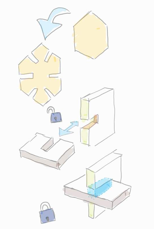
The goal is to parametrically design a construction kit that can be cut by laser and assembled freely through joints.
Parametric drawing is conserving a design's geometry and shape by applying meaningful constraints. this can save time and make any later adjustment a simple process of swapping dimensions without affecting the geometry of the design. the parametric modeling program I use is Fusion 360.
I took inspiration from nature and made a design based on bee hives, the kit design is based on hexagon chips with six slots, the joint will be a perpendicular friction fit, I had a choice between circles and hexagons but hexagons made prettier arrangements, then it was time to decide on a material, I had a choice between acrylic and cardboard, I ended up choosing cardboard because I thought its flexibility and light weight make the kit easier to handle and assemble.
I start by deciding on the key parameters of the design, these would be the dimensions I may want to adjust in the future, I set two parameters, one for the slot width named"slot" and one for the hexagon size named"size".
.jpg)
I start sketching by placing a hexagon, I place a construction line down the center to help me align the first slot.
.jpg)
I place a center rectangle intersecting the construction line and the bottom line of the hexagon and assign it initial dimensions.
.jpg)
Use the trim tool to finish the first slot.
.jpg)
Duplicate the slot by using the circular pattern tool, afterward, any adjustment to the first slot will reflect on all the generated slots.
.jpg)
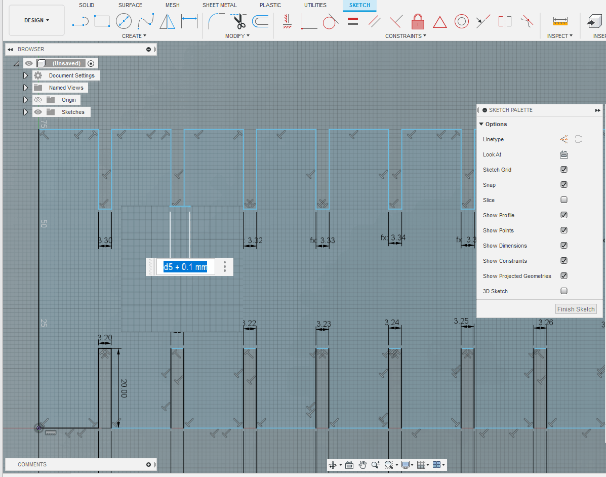
Assign the parameter we established before making the sketch to the slot width. the parameter is named slot.
.jpg)
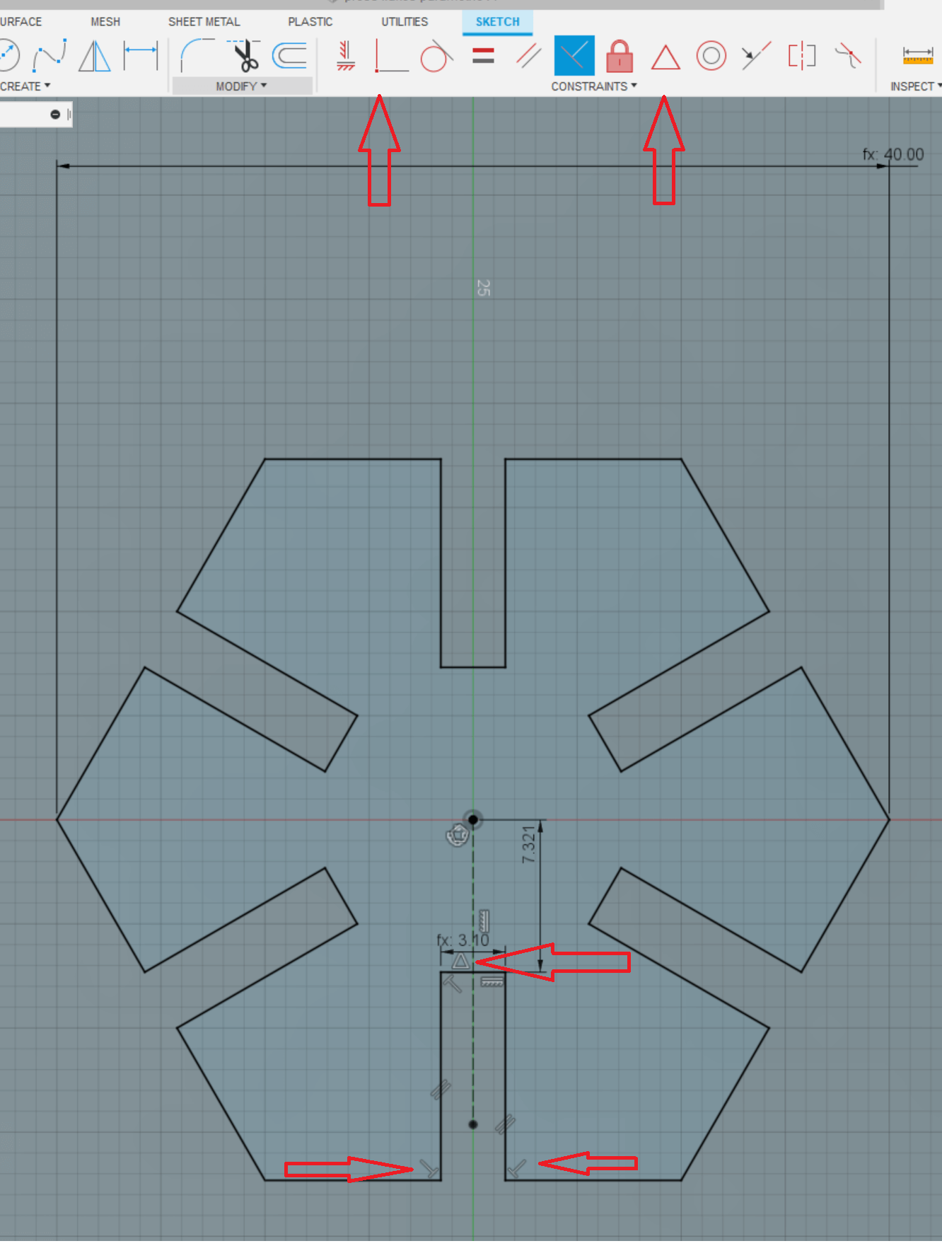
the final step is to finish constraining the sketch so that the geometry is maintained when we change any of the desired parameters. most of the constraints were added automatically by Fusion 360, all that I did was ensure perpendicular constraints in the slot edges and fix the center of the slot to the centerline of the hexagon. once fully constrained all the blue lines should turn black.
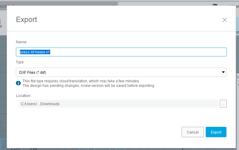
With the design finished, export it to a dxf file so that it can be opened in Inkscape, note that a licensed version of fusion 360 is required to export to .dxf format.
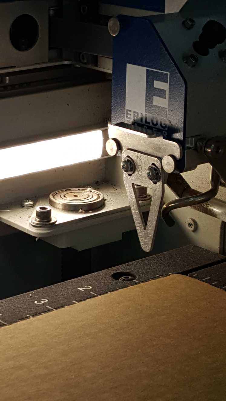
Using the laser cutter
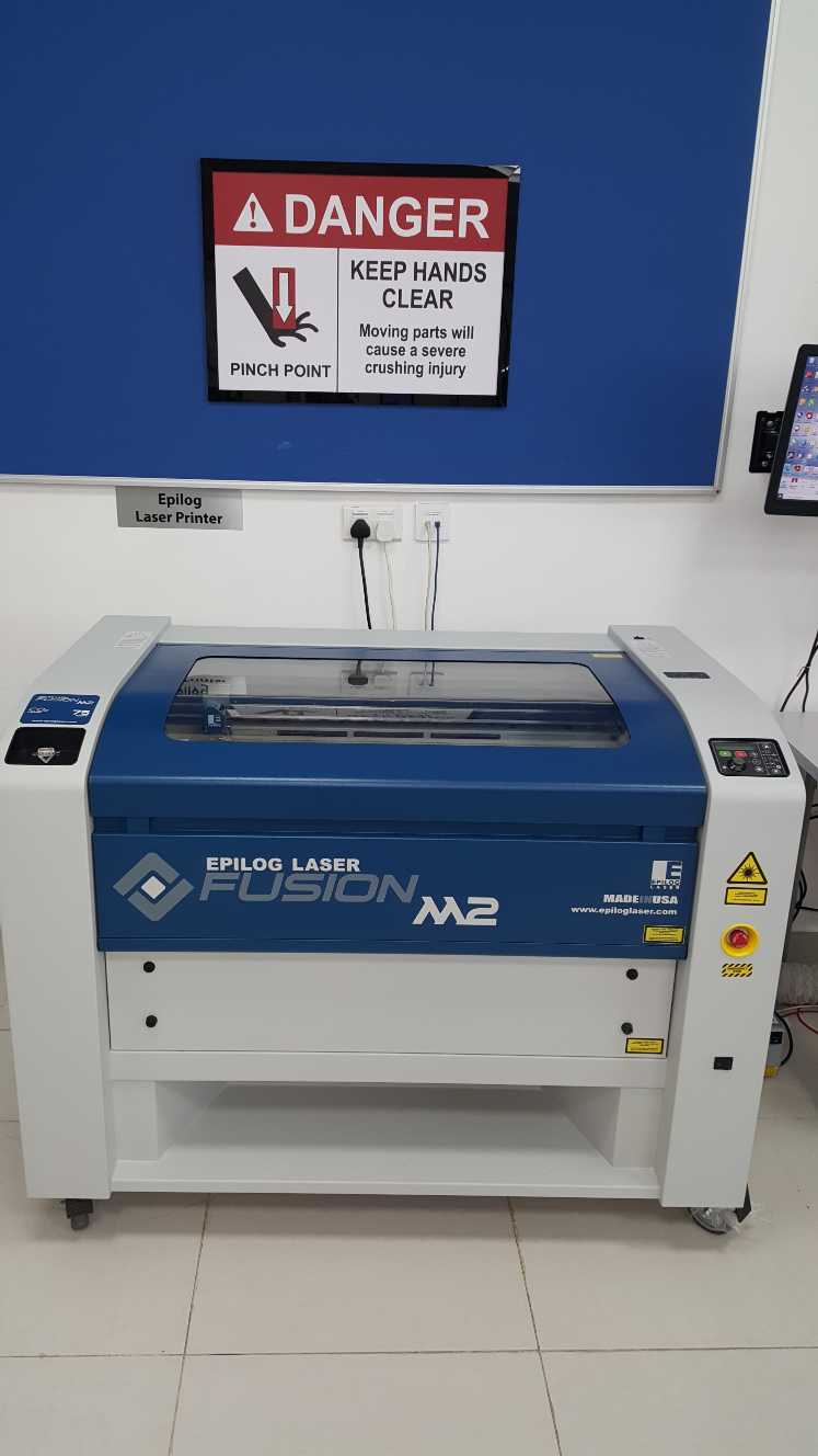
The laser cutter our lab is equipped with is Fusion M2 Epilog
-Manufacturer website
- List of the materials it can process.
-The operation manual
The three basic settings to use are:
-Power: Determines the amount of laser energy that is delivered to the piece being cut and is adjustable in 1% increments from 0 to 100%. The higher the power, the deeper the cut
-Speed: Determines the travel speed of the carriage in vector cutting mode and is adjustable in 1% increments from 1 to 100%. The slower the speed, the deeper the cut.
-Frequency: The number of laser pulses that the laser fires per inch of travel. The frequency is set in the dashboard and can be adjusted from 1 to 100. A lower frequency number will have the effect of less heat because fewer pulses are being used to cut the material.
the software for the cutter is configured to use a specific yellow color for vector cutting and a specific red color for rastering.
Basics of operation
Software preparations
The workflow for using the software during this assignment was as follow:
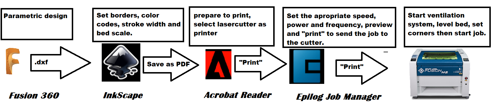
Export the 2d drawing from Fusion 360 as .dxf file
In inkscape, give the drawing a yellow border by shift click the yellow color (R:255, G:255, b:0, A:1), note:this step is only due to the setting of the cutter profile which is set to identify this color as the vector cut line and can be changed from the cutter software.
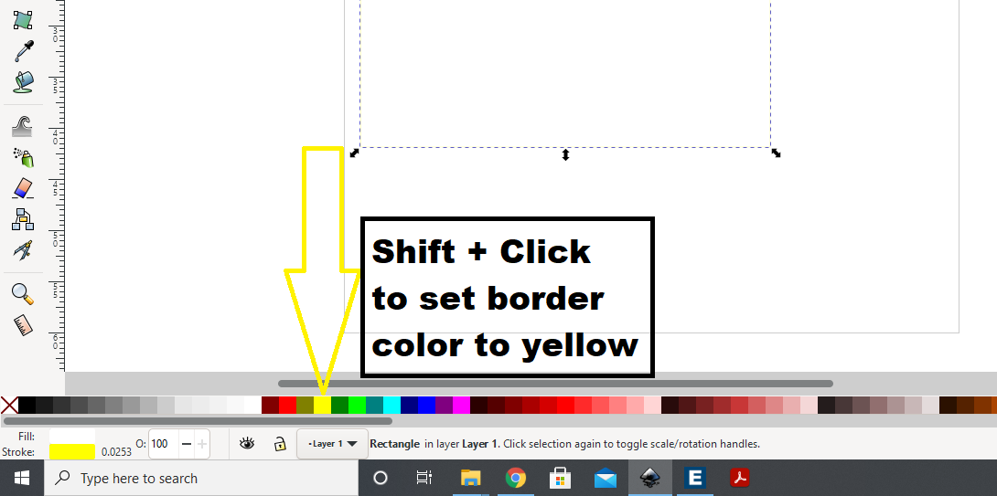
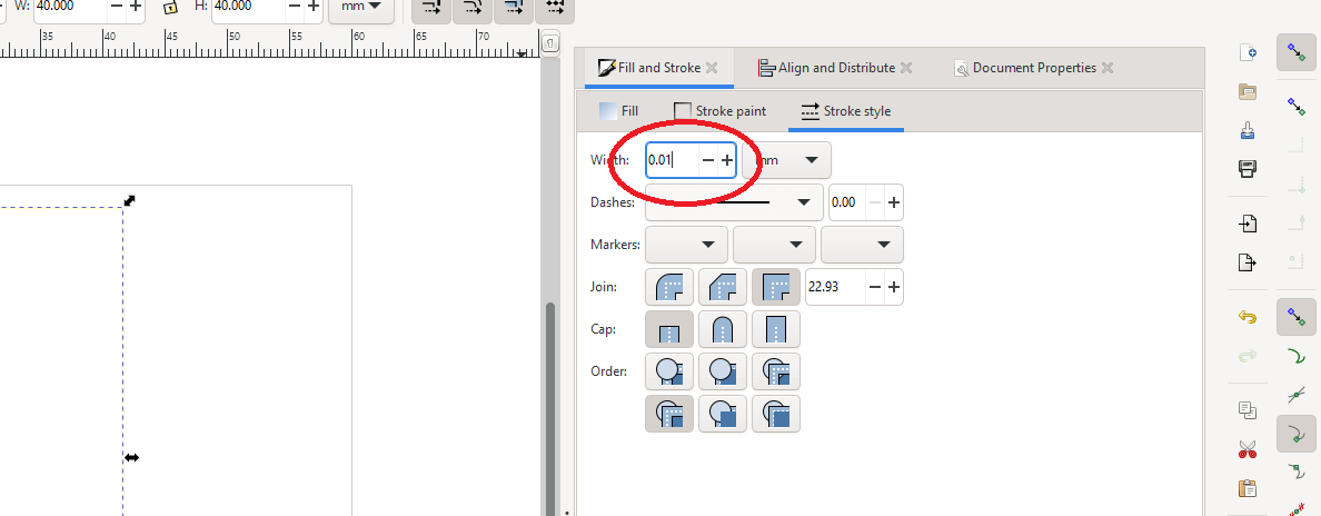
Make sure to set the stroke for the border where the laser will move to the minimum value possible, here it is 0.01mm
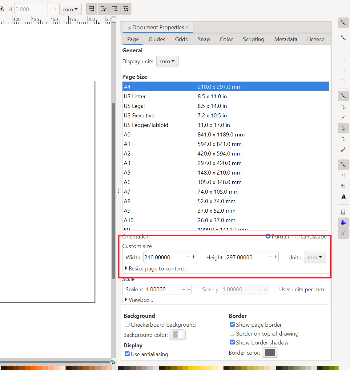
Change the size to match the amount of the material laying on the cutter bed.
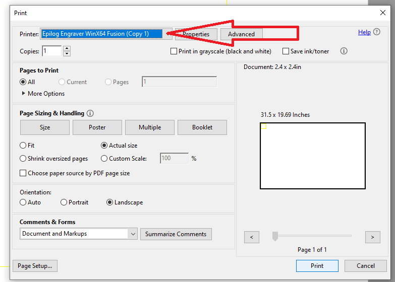
Save as pdf file, open the file in acrobat reader and go to print settings, make sure to select the laser cutter then click print. this won't actually start the cutter, but will send a cut job to the Epilog software which will handle setting up the cutting process.
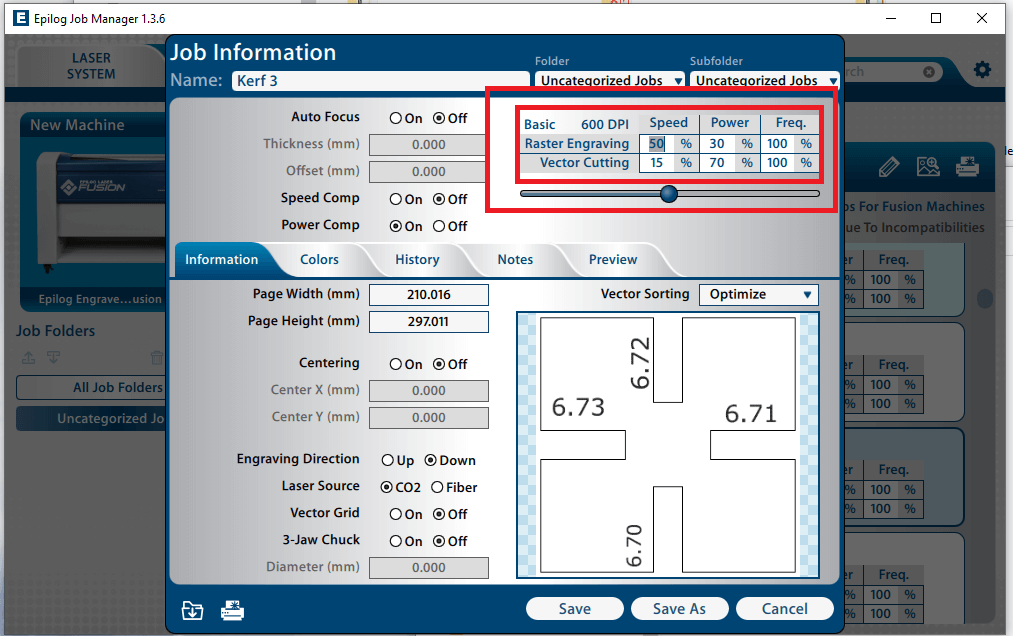
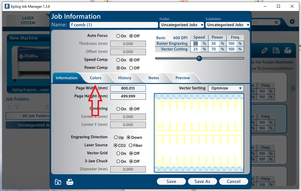
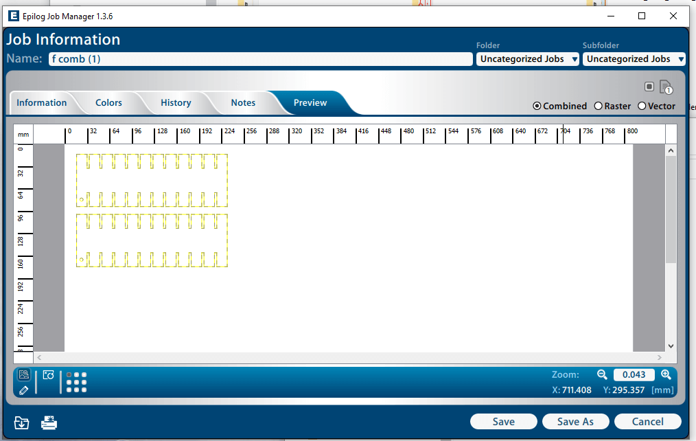
now we move to the Epilog Job Manager, here we should see our file on the top of the job list. double click to open its settings.
.png)
On the top right we see the basic options to control the speed, power and frequency, these options would be different for every material.
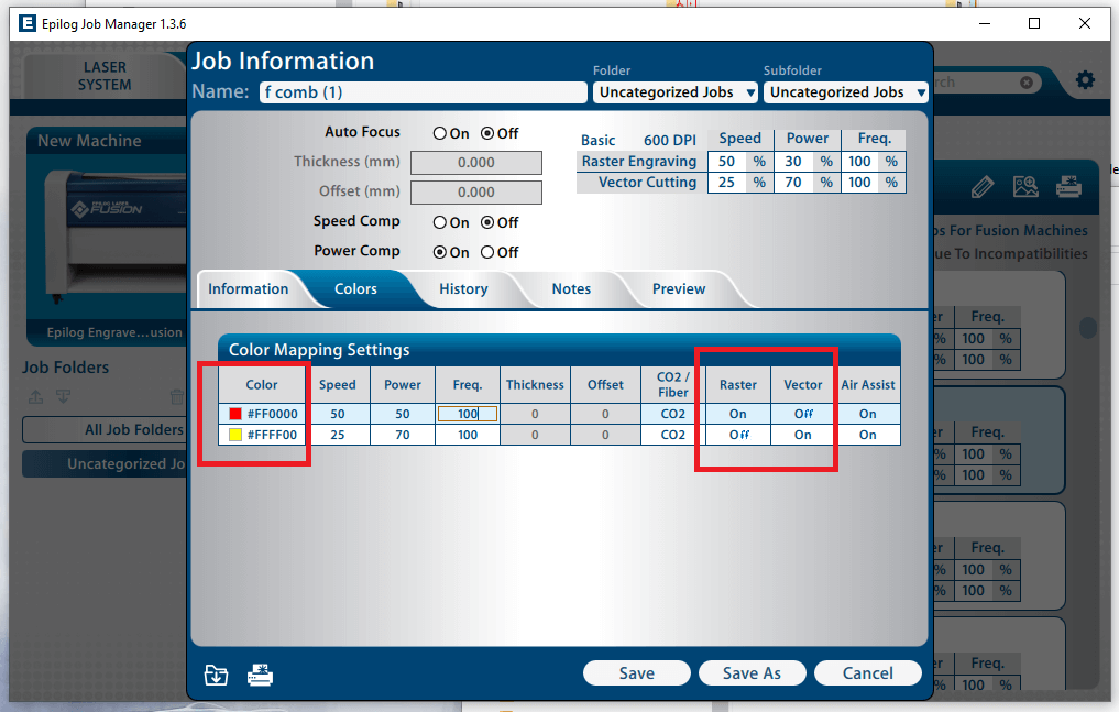
in the color tab we can set specific speed, power frequency profiles to different parts of the same sketch and have finer control based on the line's color
Here we see that the red and yellow color have different profiles
In the preview tab we can view what parts of the sketch would be vectored and what would be rastered, the colors are visible and indicate their appropriate profile.

When we're satisfied with the settings we can proceed to hit print which will send the job to the laser cutter, from here we move to the hardware side.
Laser cutter operating the hardware
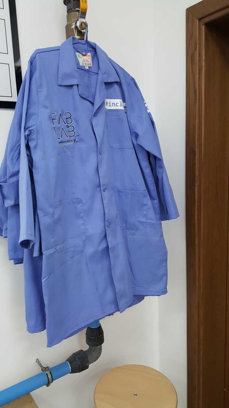
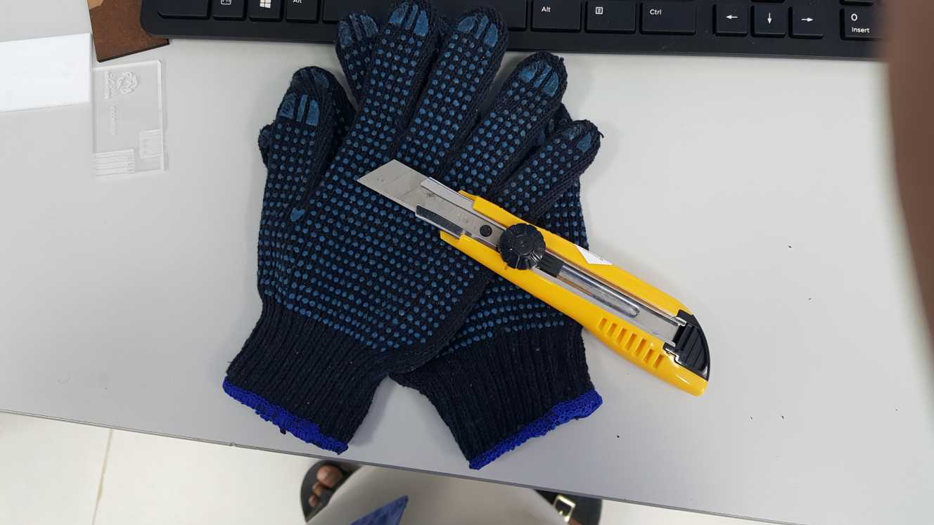
Safety
First of all make sure to use the required safety gear, the Epilog M2 is a Class 2 laser product, eye protection is not mandatory. the safety gear to use is Lab coat, mask and gloves when using a knife or saw to precut the material to fit into the laser machine, there is an emergency shutoff button on the right side of the machine, Do not open the led of the machine incase of small fire or the oxygen in the air could feed the fire, always turn on the ventilation system when using the laser machine.
The machine
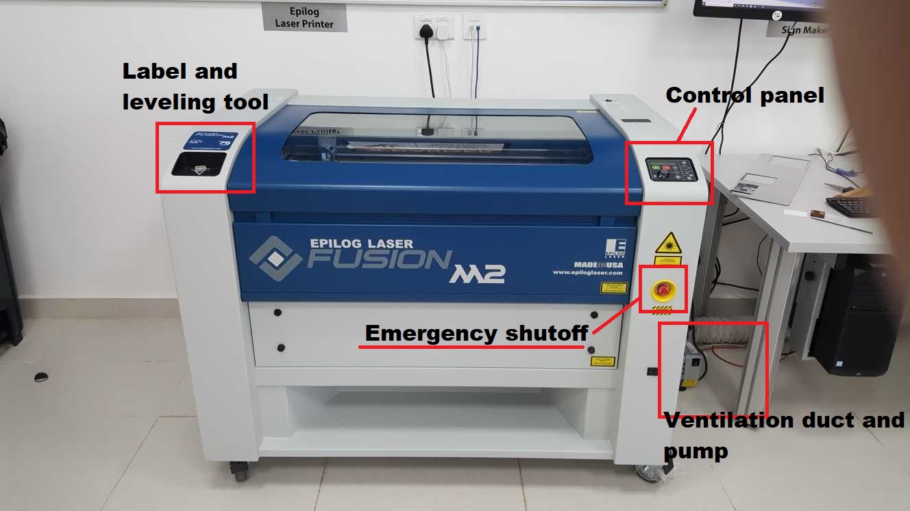
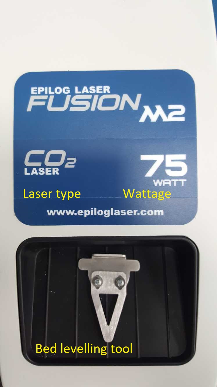
The label shows the laser specifications and have a storage compartment for the focus tool.
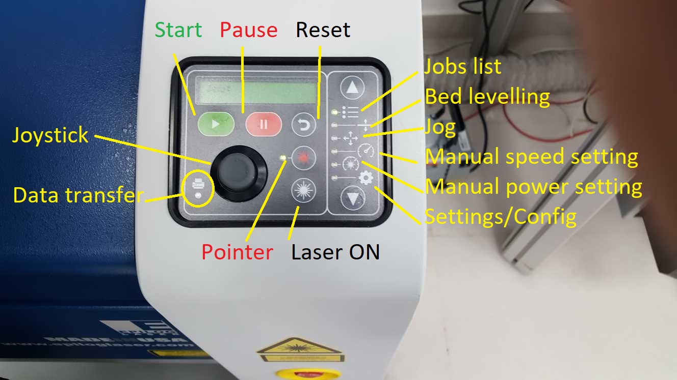
The control panel have machine controls and from here we can launch cut jobs and manually change setting like speed, power, home point and focus.
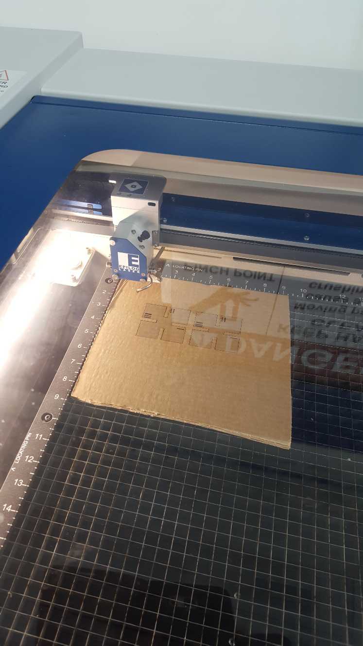
Operation
open the led
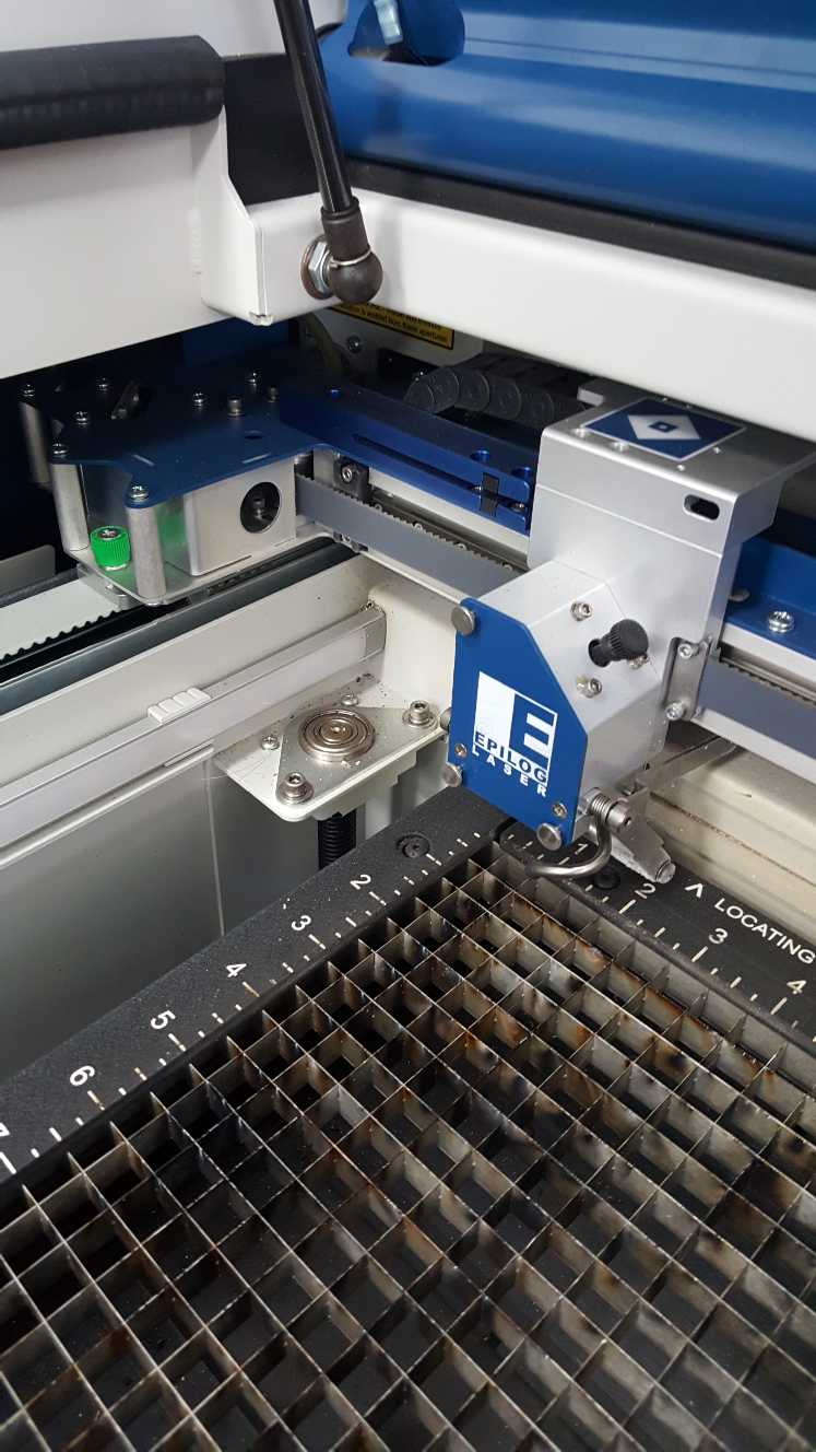
Place the material on the corner. put the focusing tool on the laser carriage.
 Once we put the material on the bed it's time to set the focus. from the control panel we select bed leveling/focus and use the joystick to move the bed, the up down of the stick moves the bed up and down, moving the stick left or right switches between course(fast) and fine(slow) movement, with the focus tool mounted on the laser carriage and the material resting on the bed, move the bed up or down until the focus tool is barely touching the material, there is no sensors so look carefully and use your judgment, pressing the center button sets the height of the bed.
To set the home point, select jog on the control panel, the joystick will move the laser carriage according to the direction held on the stick, turn on the pointer laser to preview where the laser is looking down at, when satisfied with the location press the center click to set the new home point.
With the focus and home point set, the machine is ready, go to the Jobs menu and press to begin cutting.
Steps to laser cutting the press fit kit:
Material: corrugated cardboard.
-step 1: find the kerf for the material.
-Step 2: test the kerf value with the desired joint type,
-step 3: with the values obtained from step 2, adjusted the offset of the kerf in the press fit kit sketch.
-step 4: cut the designed press kit.
Step 1: Kerf
Kerf is the material removed during the cutting process, for laser cutting kerf depends on the width of the laser beam and the material used. 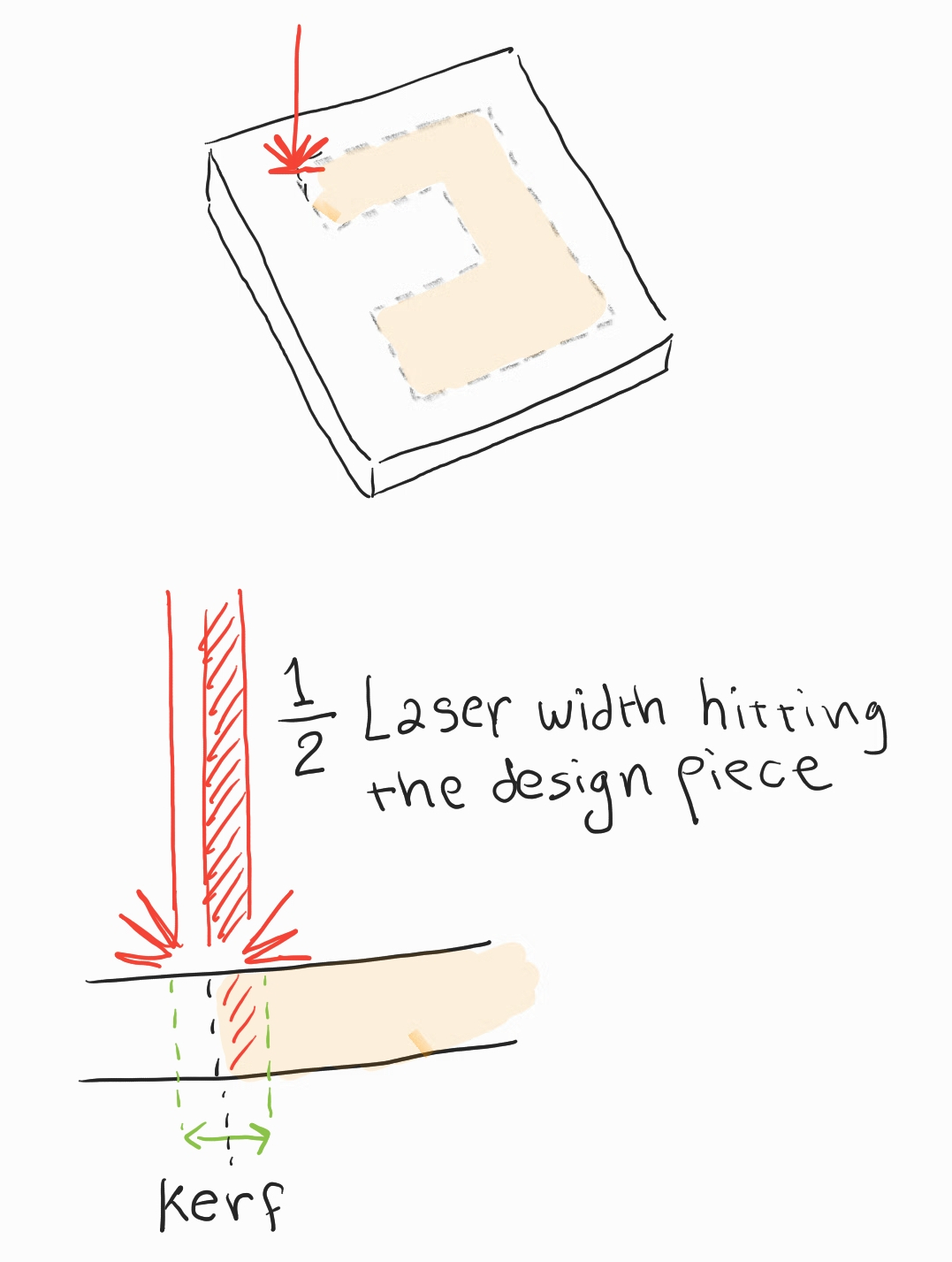
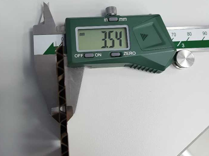
to find out the kerf value I cut a 40mm by 40mm square and measure the difference in dimensions between the sketch and the actual cut material.
using a caliber I measured an average value of 39.75mm
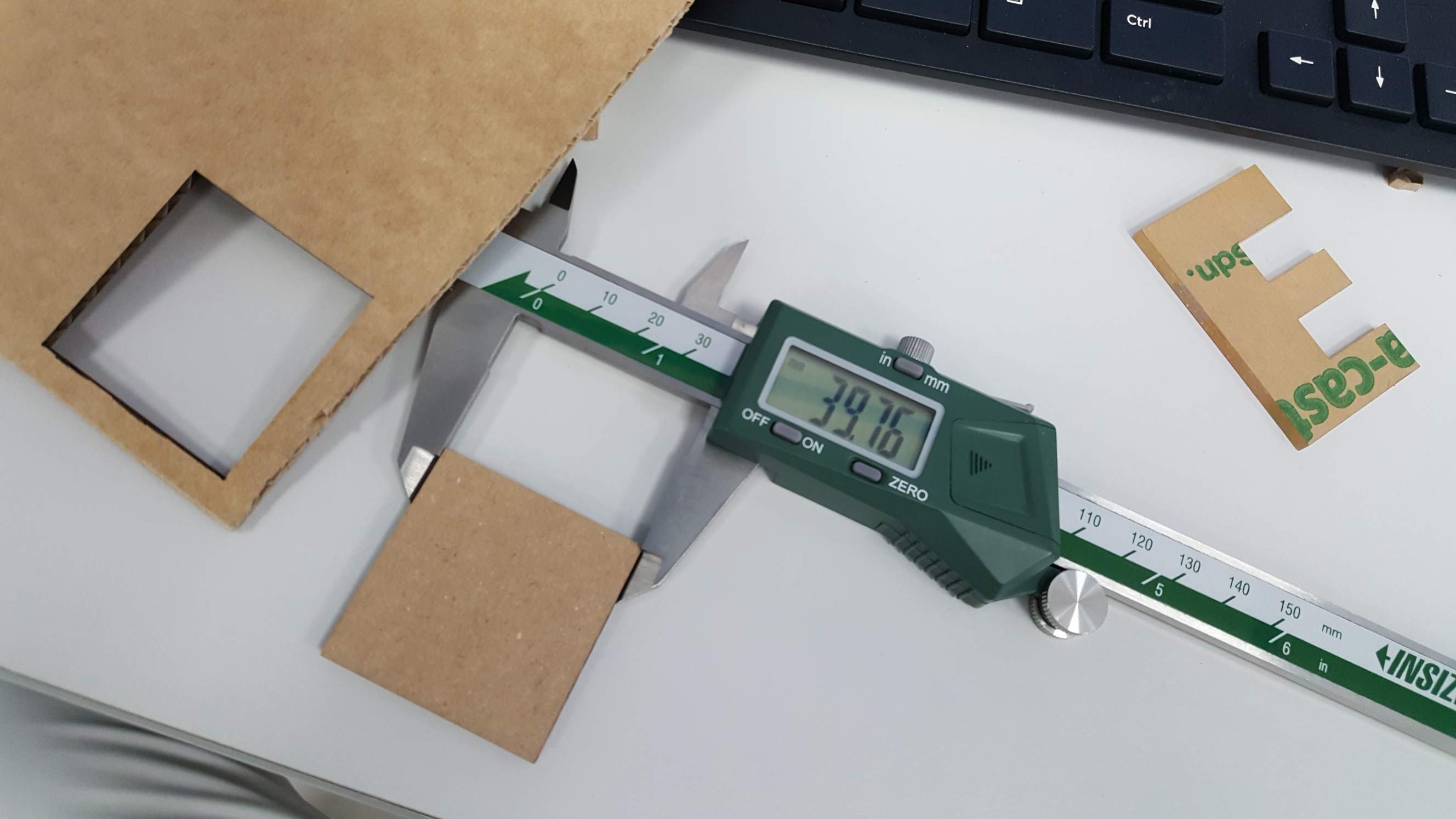
The kerf should be the difference between the design and the measured value:
Measured kerf = Sketch mm - cut piece mm
Measured kerf =40mm - 39.75mm = 0.25mm
since only half of the beam cuts inside the material the value we should use is half of the kerf so we use 0.125mm as the final value.
Step 2: Tolerance test
with the value of the kerf, we can proced to testing the joint tolerance, my first test was a square with four slots:
.png)
I made an error here and used a base value of 4mm which is larger than the material's depth of 3mm+.
The end result was that all the slots were a loose fit, I noted my mistake and for my second attempt I designed a parametric comb with incrementally increasing slot width.
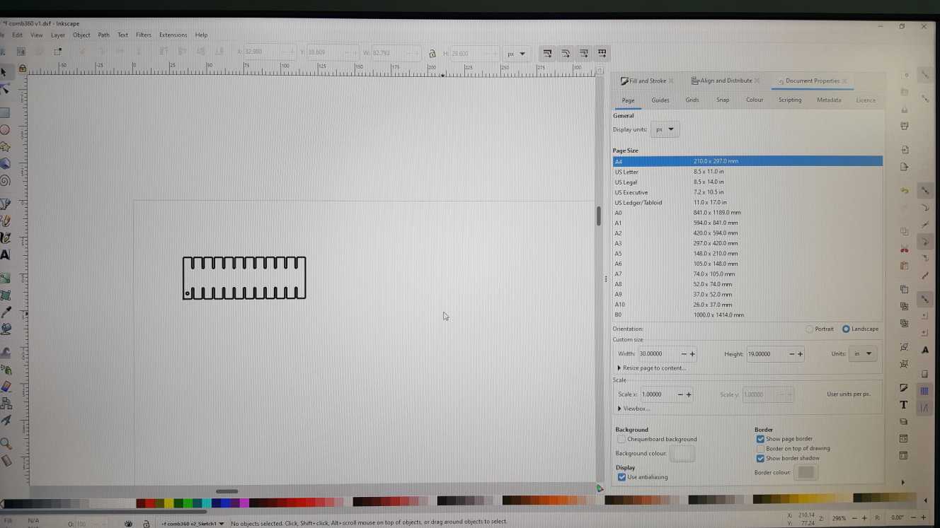
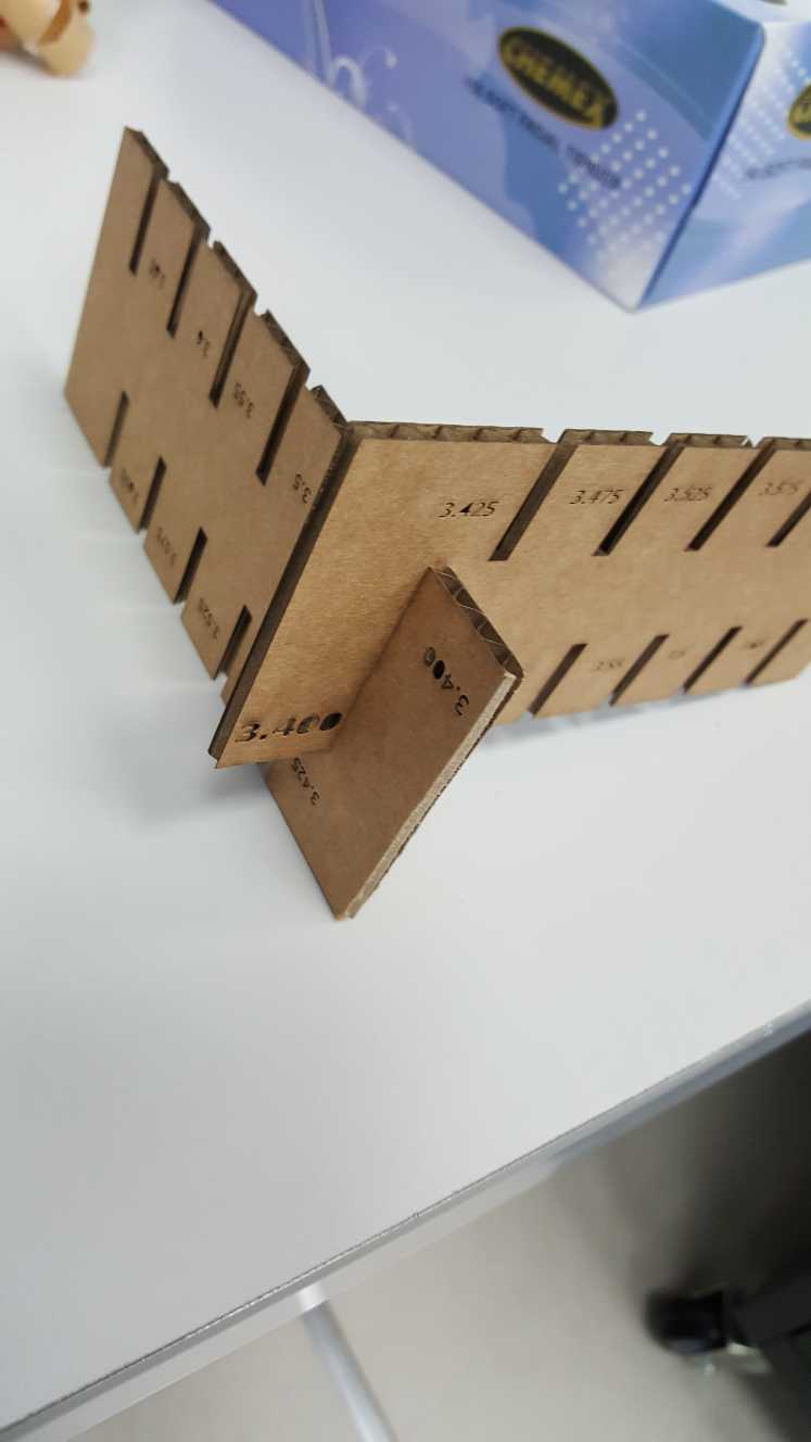
With this comb I decided on using a kerf offset value of 0.1mm for my press fit kit. so the slot size will equal the thickness of the material + the kerf offset. 3mm + 0.1mm = 3.1mm slot width.
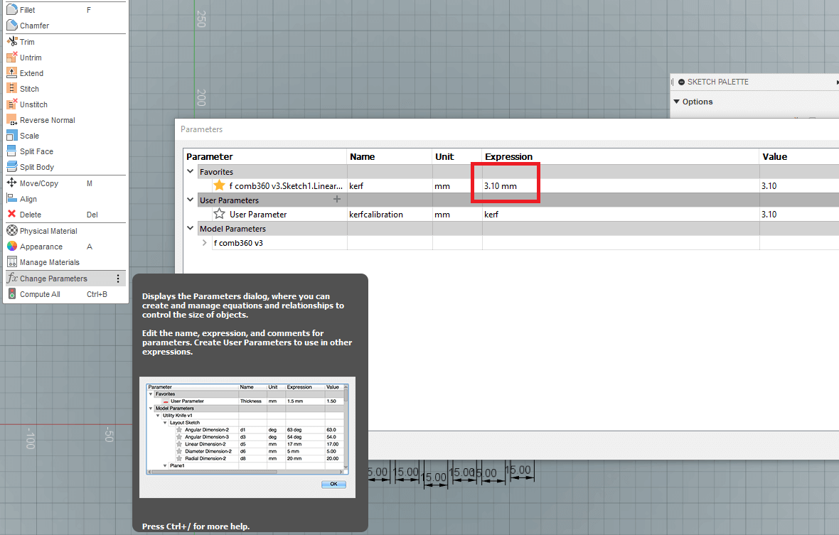
Step 3: Set the offset in the press fit kit design
Since the design I made is parametric, all I need to do is set the value though either the parameter window, or click on the slot and change its width manually, this will change the width for all the slots in the design.
Step 4: Cut and assemble
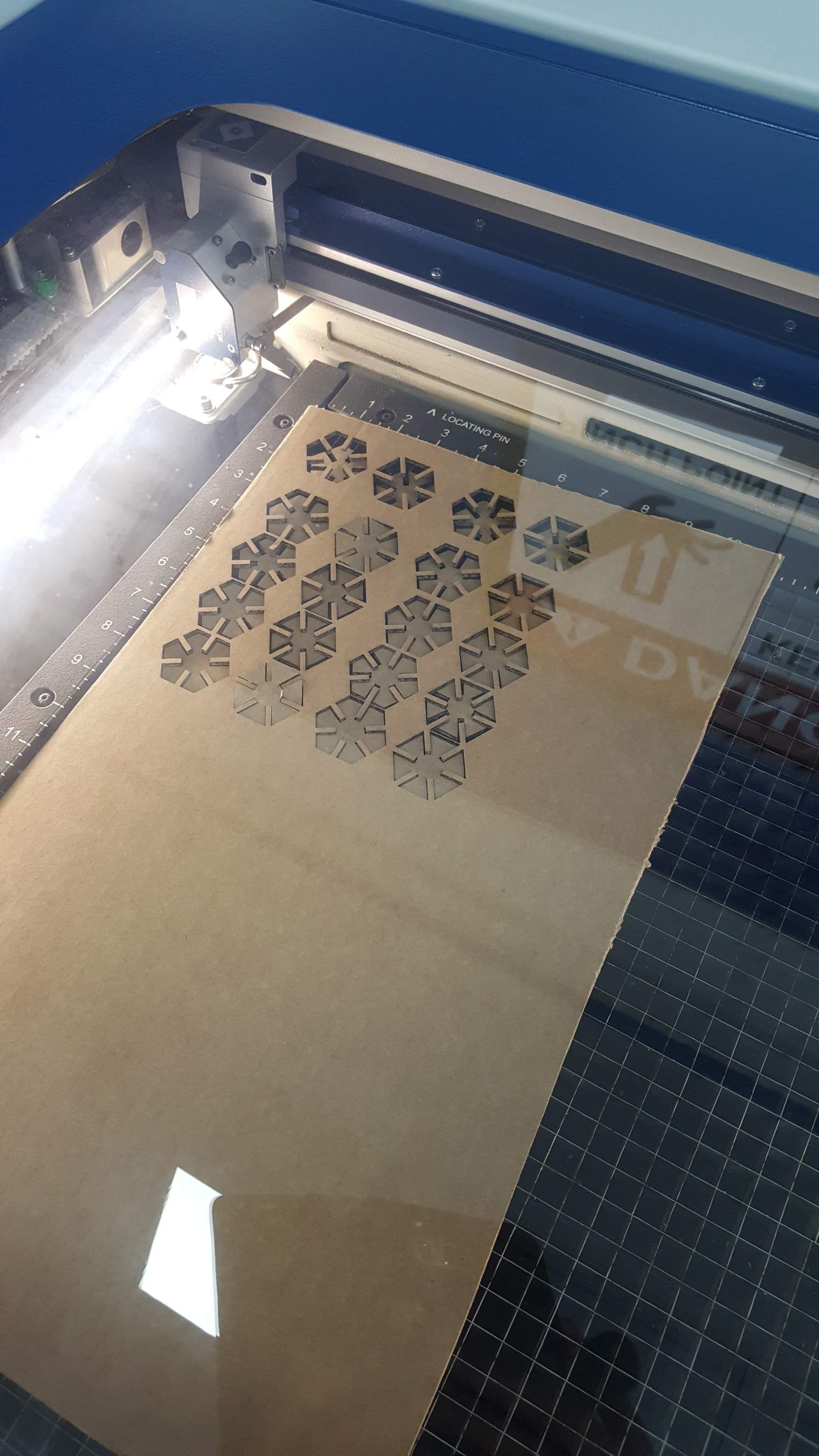
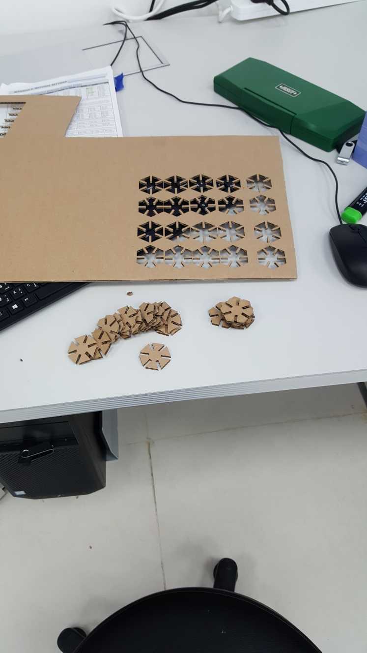
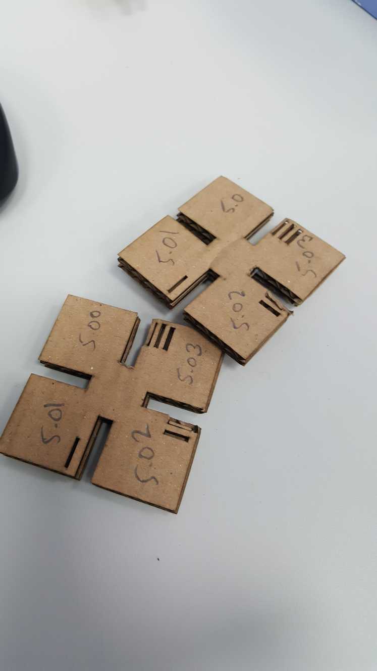
Assembled:
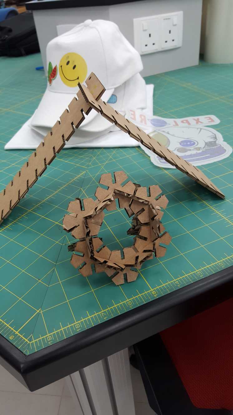
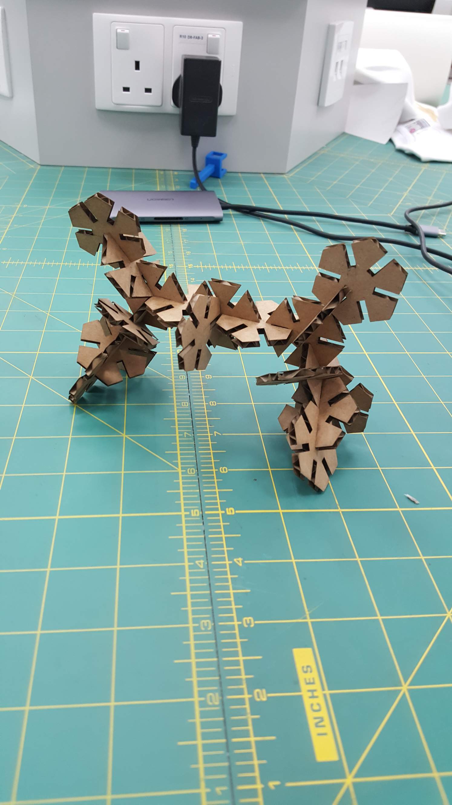
The kit is finished and it fits well, the hexagonal shape allows us to create many good looking arrangements.
Trouble shooting
I faced a number of issues during this assignment, the first is the material I choose the corrugated cardboard, this material does not have a consistent thickness, the value I measured tended to fluctuate between 0.1mm and 0.4mm, furthermore the material had a little bit of flex making taking an accurate measurement with the caliber more difficult. the way I dealt with this issue is by taking several careful measurements from different points of the material and averaging them but the average value was still larger than what would've given me a good fit, so I just made a calibration comb with a wide range of values less than and greater than the average value which finally allowed me to get a good fit.
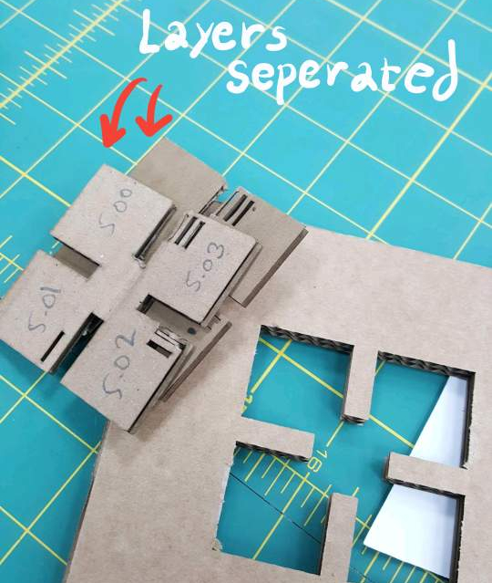
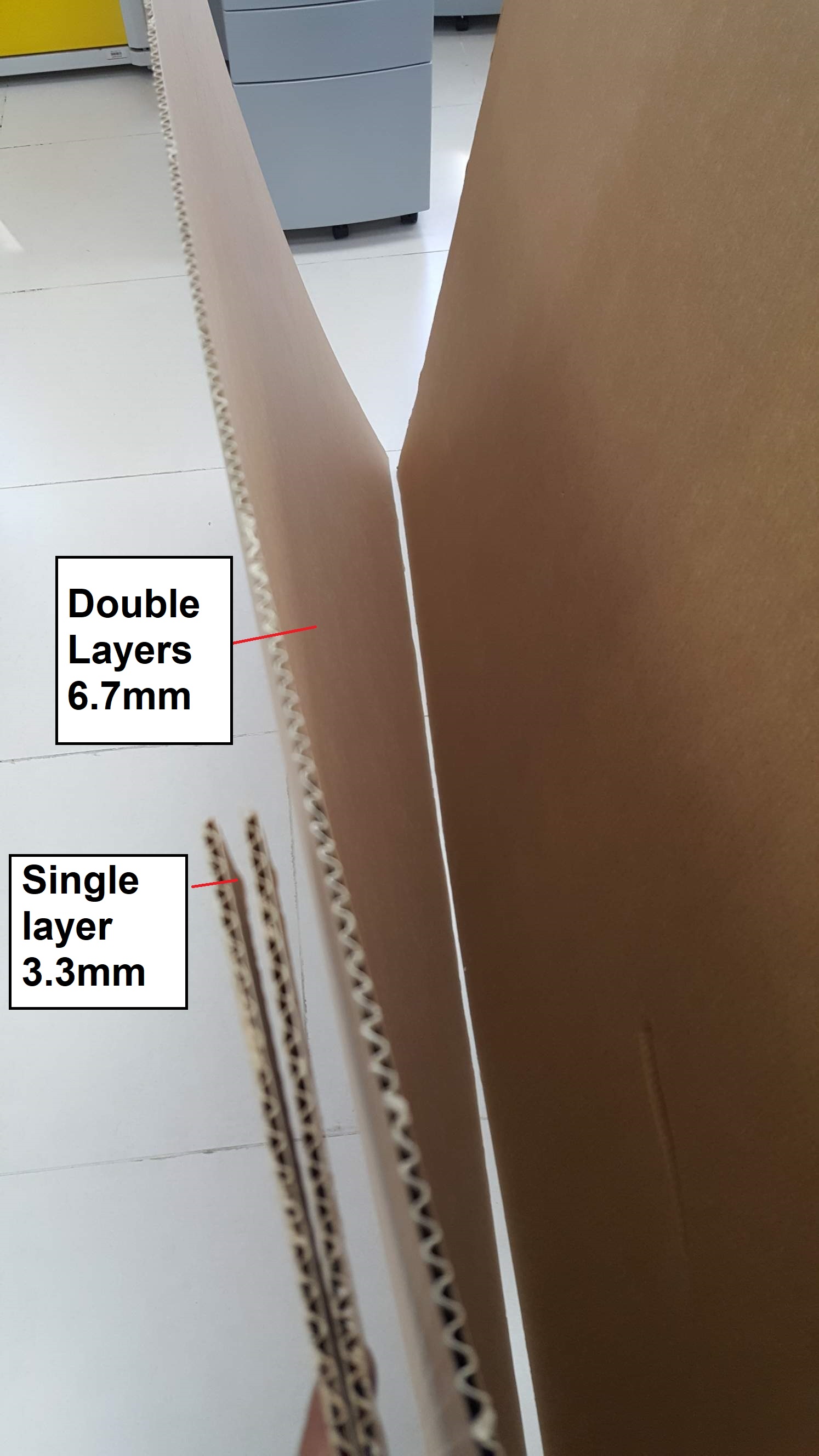
the other issue I faced was that I first tried to use a double layer cardboard material. but upon cutting it the layers would separate, the conditions for the assignment is to not use glue so I decided on changing the material to single layer cardboard.
An issue I faced with InkScape is that it sometimes will scale .dxf files incorrectly, just pay attention to the dimensions of the sketch in inkscape and adjust when needed.
In the Epilog Job Manager always double check the color codes and cut profile, I ended up rastering one of the jobs that I wanted to cut which is a small error but have the profile been set to a material like wood or acrylic it could've ended up with a fire when used with cardboard.
During assembling I had some difficulty lining the slots together, this issue could have been avoided have I made a chamfer in the slot design, which would've acted as a guide for the slot to mesh together.
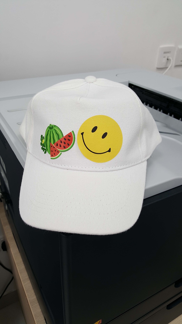
Vinyl Cutting.
this part has been done in week 2 Computer aided design. click the link on the header to to week 2.