GROUP ASSIGNMENT
Computer Controlled Cutting
Measuring the Kerf
Kerf is the material removed during the cutting process, for laser cutting kerf depends on the width of the laser beam and the material used. 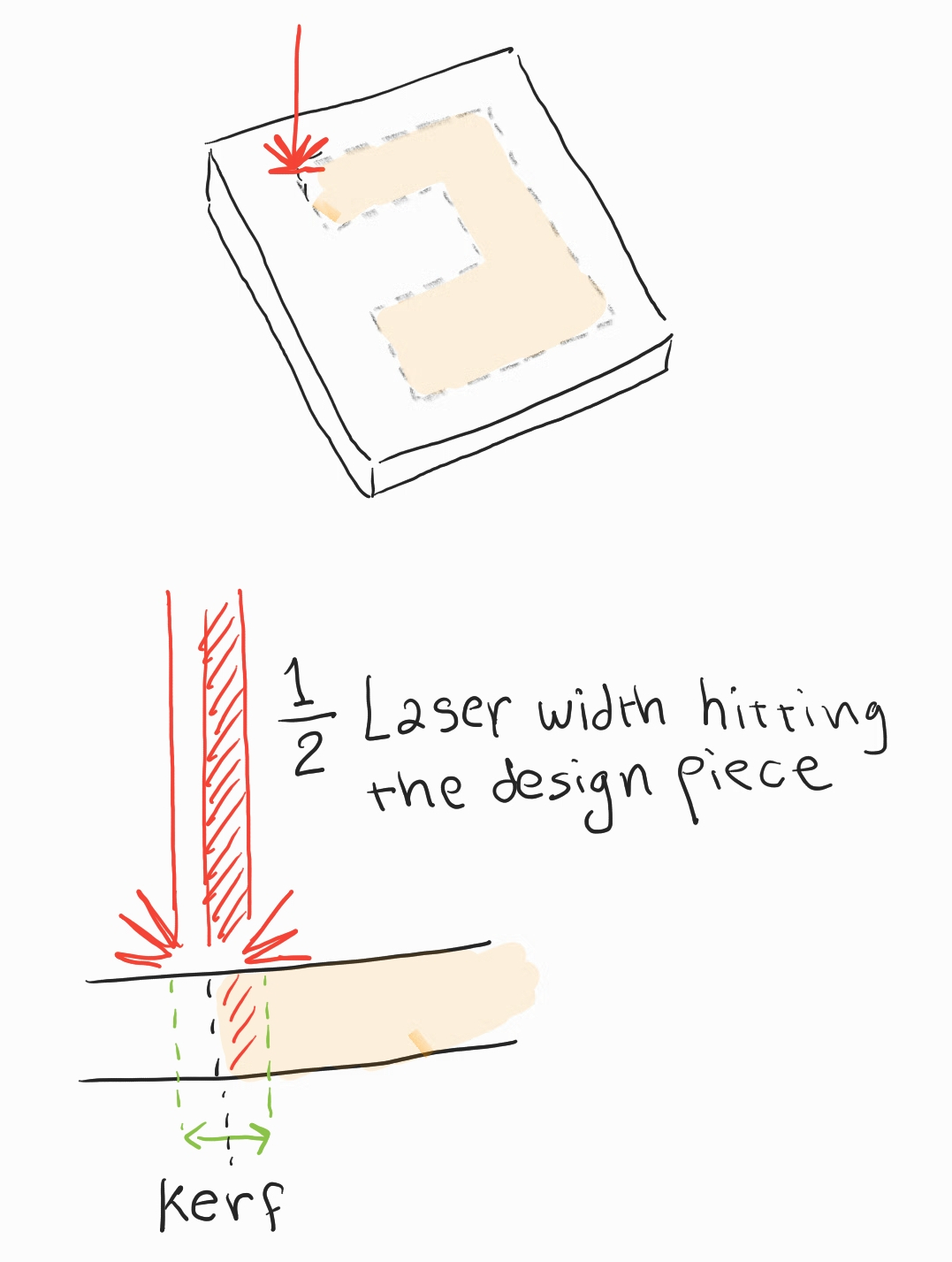
to find out the kerf value I cut a 40mm by 40mm square and measure the difference in dimensions between the sketch and the actual cut material.
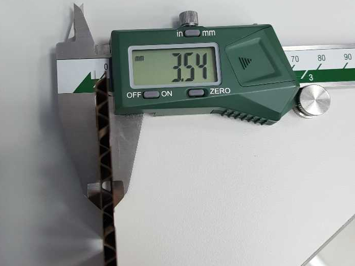
using a caliber I measured an average value of 39.75mm
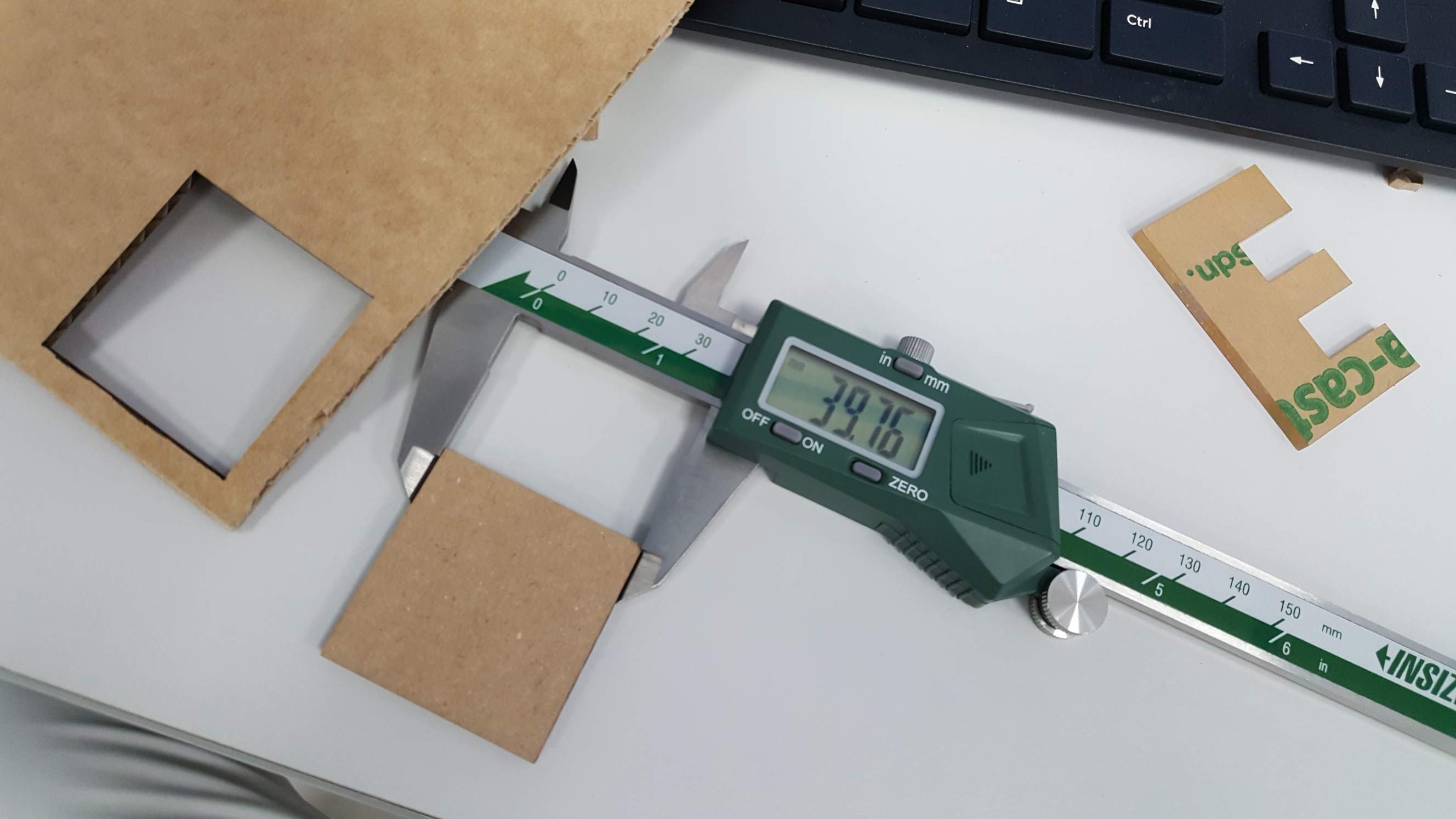
The kerf should be the difference between the design and the measured value:
Measured kerf = Sketch mm - cut piece mm
Measured kerf =40mm - 39.75mm = 0.25mm
since only half of the beam cuts inside the material the value we should use is half of the kerf so we use 0.125mm as the final value.
Tolerance test
with the value of the kerf, we can proced to testing the joint tolerance, my first test was a square with four slots:
.png)
I made an error here and used a base value of 4mm which is larger than the material's depth of 3mm+.
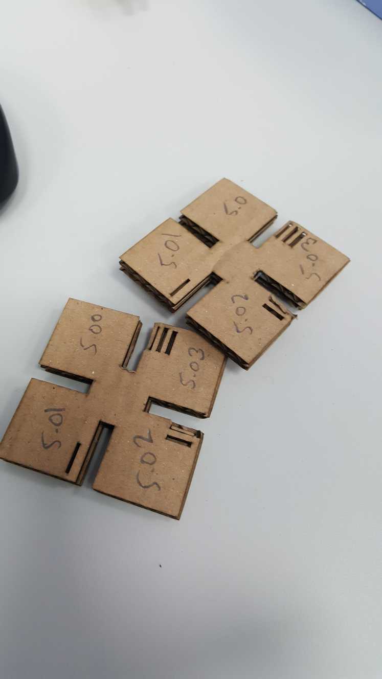
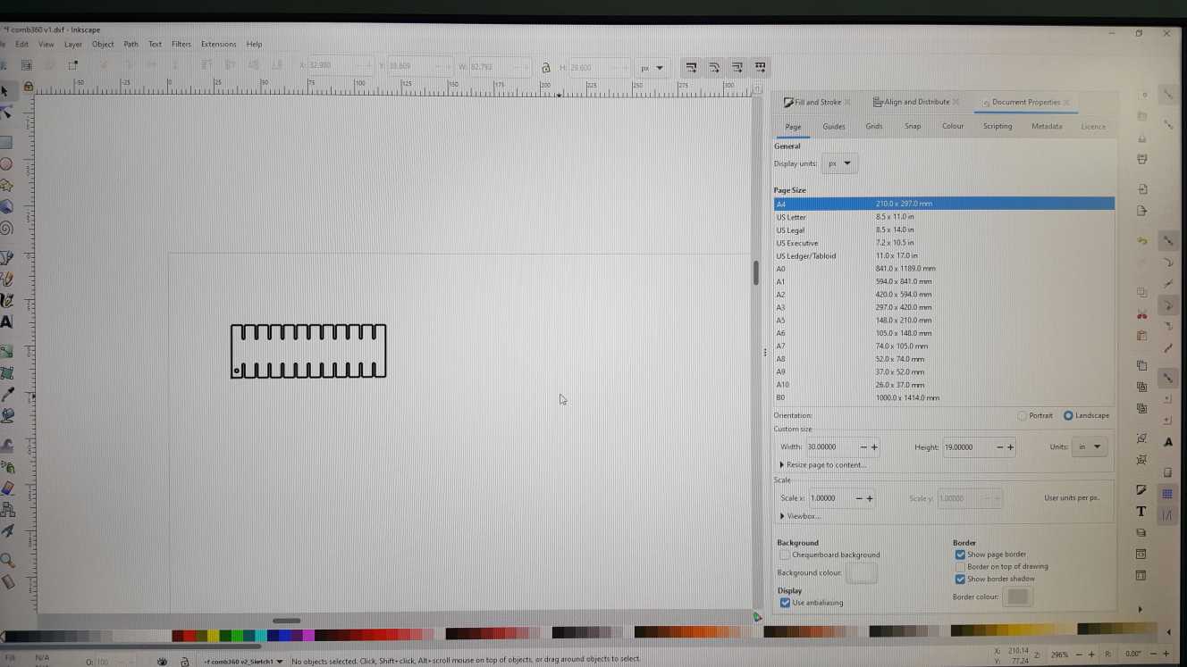
The end result was that all the slots were a loose fit, I noted my mistake and for my second attempt I designed a parametric comb with incrementally increasing slot width.
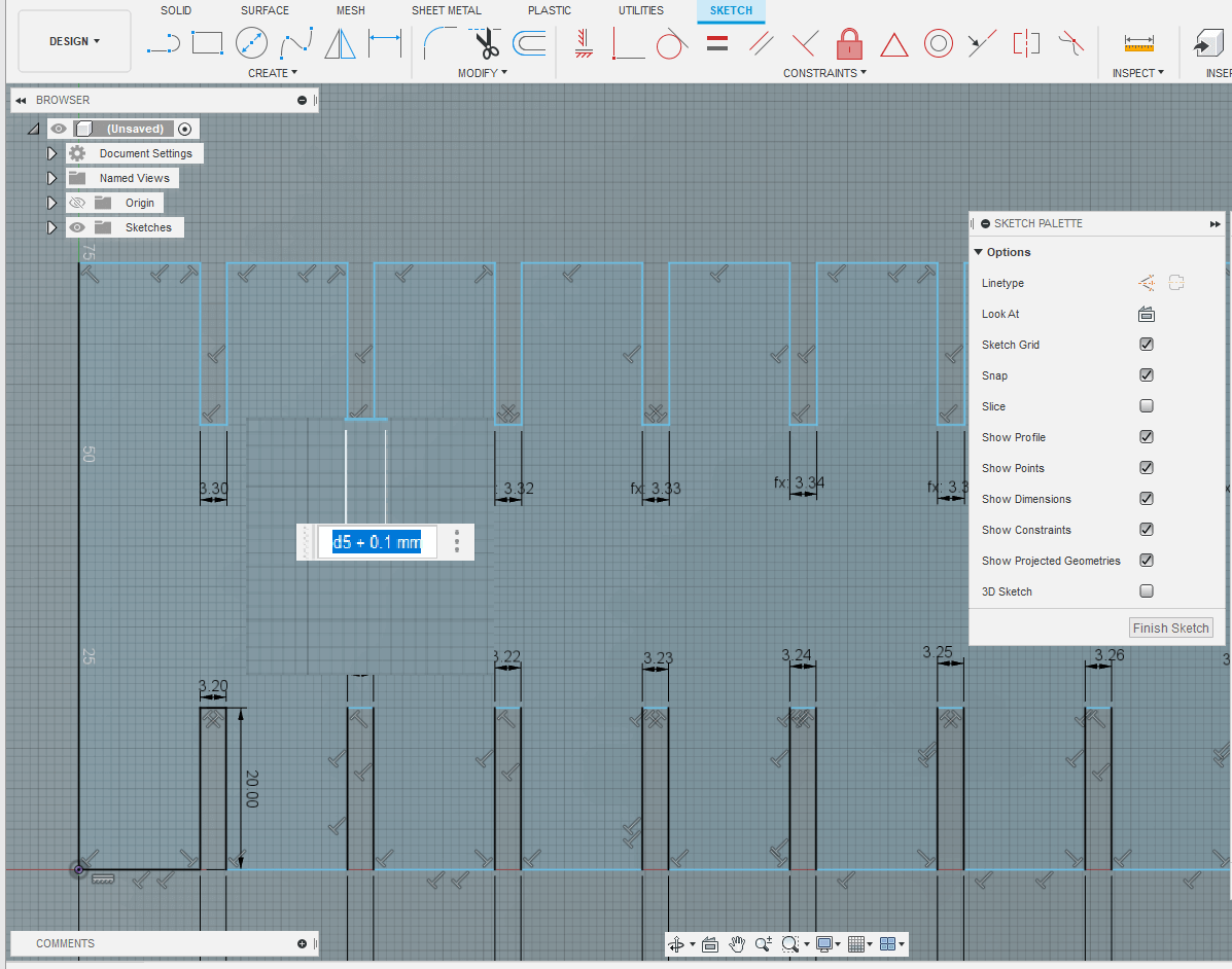
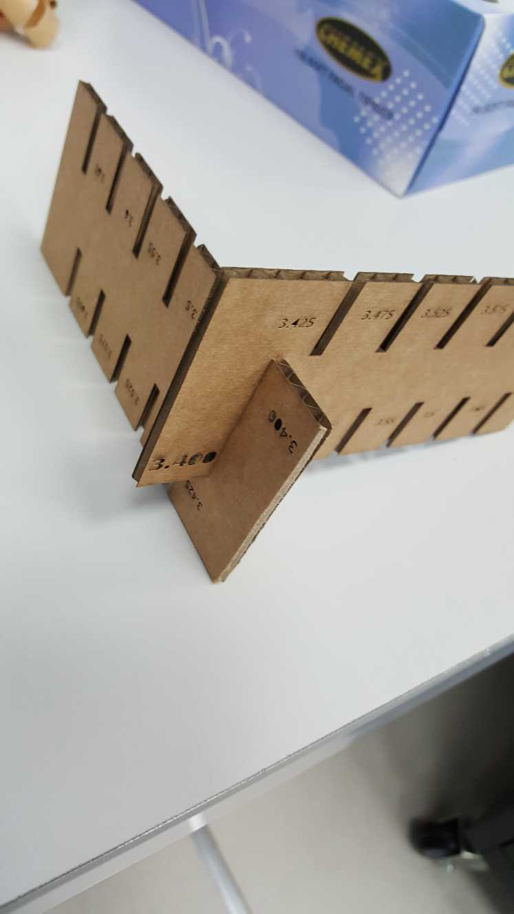
With this comb we decided on using a kerf offset value of 0.1mm for my press fit kit which will be designed in the individual work. so the slot size will equal the thickness of the material + the kerf offset. 3mm + 0.1mm = 3.1mm slot width.