

******************************************************************************
Embedded Programming
Group assignment:
• Compare the performance and development workflows for other architectures.
• Document your work to the group work page and reflect on your individual page what you learned
Individual assignment:
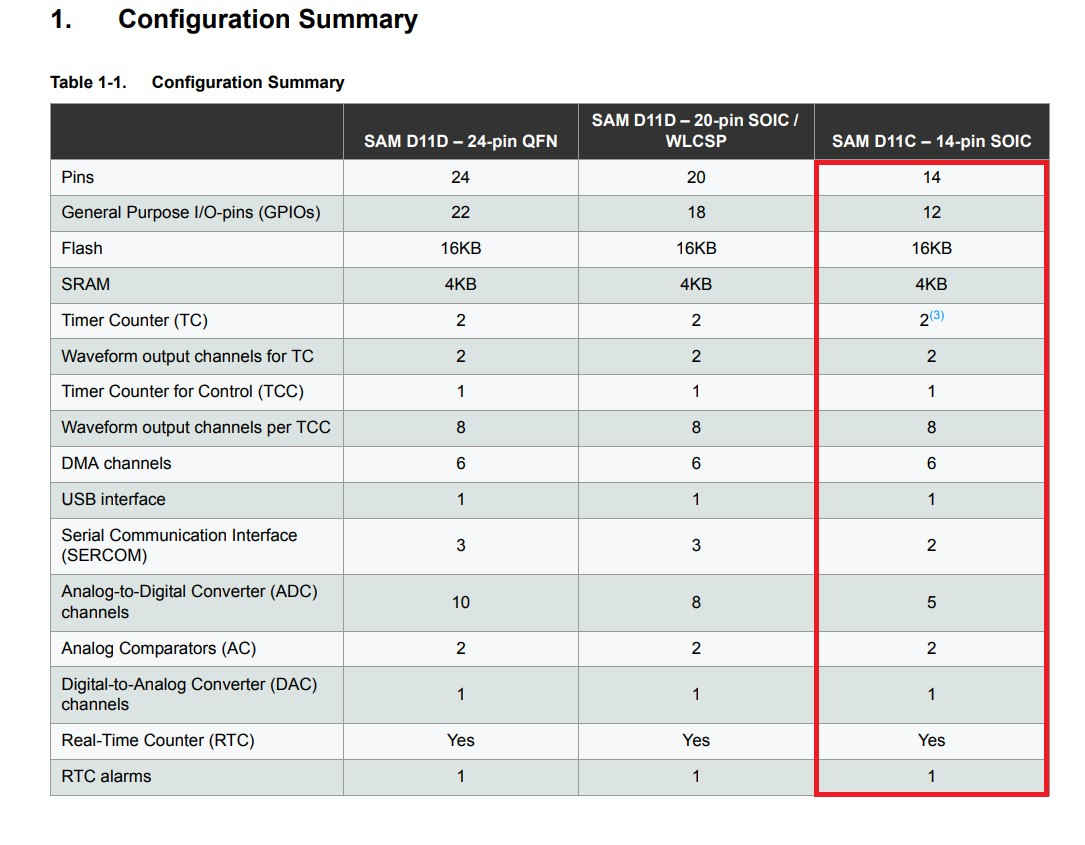
• Read the datasheet for your microcontroller
• Use your programmer to program your board to do something
*****************************************************************************
(1) Welcome to Embedded Programming Week, the goal of this assignment is to learn more about microcontrollers and program them to perform tasks. I will use the boards I built during the week of electronics production and electronic design:
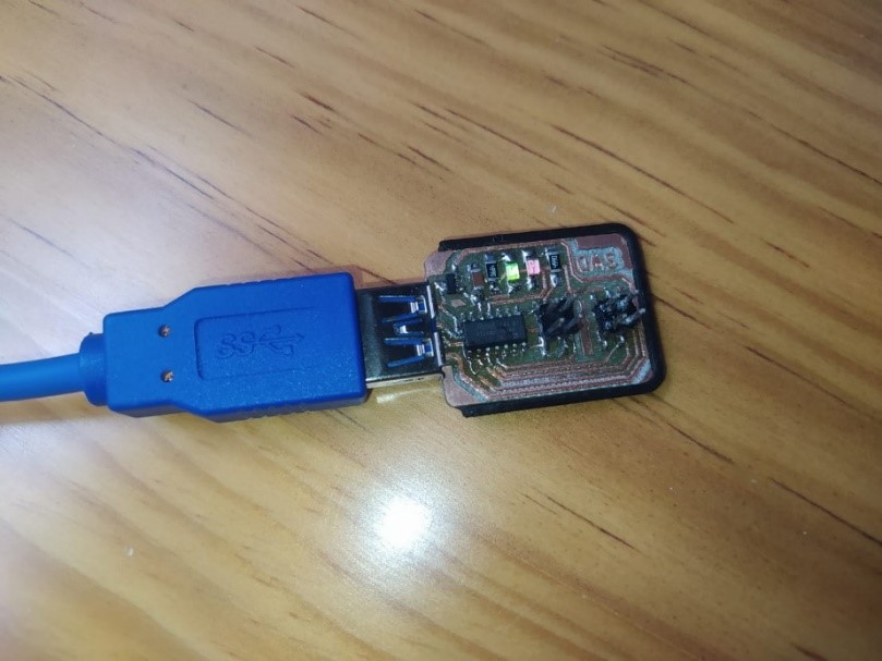
SDW programmer – Based on SAMD11C14A.
https://gitlab.fabcloud.org/pub/programmers/programmer-swd-d11c
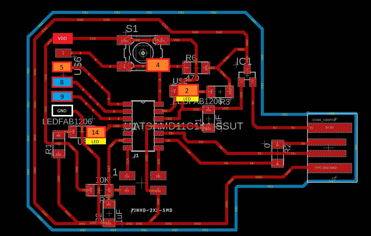
Guitardino, Board inspired by the Samdino by Adrian Torres - Based on SAMD11C14A.
http://fabacademy.org/2020/labs/leon/students/adrian-torres/samdino.html
You can review the entire SDW manufacturing and programming process here:
https://fabacademy.org/2022/labs/ciudadmexico/students/josemanuel-diaz/a5.html
Below I will make a brief summary of the programming of both boards:
The SDW is a simple to use programmer, it also has a great advantage when working with SAMD11C microcontrollers: it only needs to be used once to program the boards, later they can be programmed from the USB port.

(2)In my case I used another SDW programmer to program my SDW
(3) Before starting with the programming of the SDW we need to verify the quality of the machining and assembly of components:
• Continuity of the tracks according to the design
• The correct location and polarity of components
• Tracks joined by welding, if they exist, correct their position.
Now we need to load the bootloader for our programmer to work, for this we must have the following resources.
1. EDBG latest version, you can download it from here.
https://taradov.com/bin/edbg/
Select the corresponding operating system and version.
2. Bootloader
You can download the latest version here.
https://gitlab.fabcloud.org/pub/programmers/programmer-swd-d11c
3. All of the above must be in the same folder.
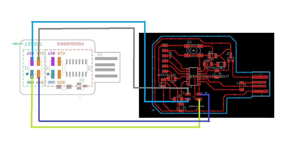
(4) If, like me, you use another SWD programmer, you will only need a cable made with 4 female-to-female jumpers to communicate with both programmer.
(5) We must recognize the output pins
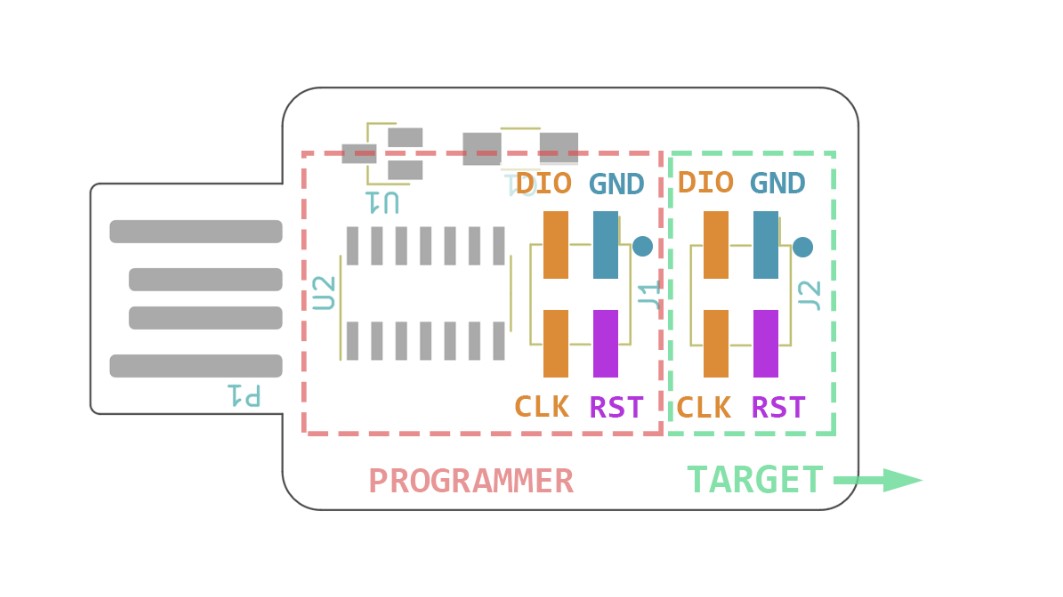
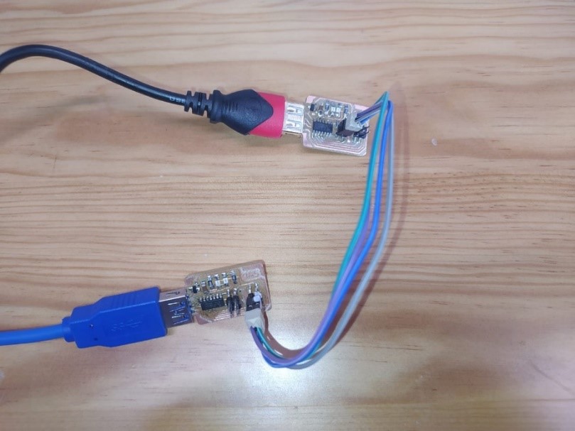
(6) J2 is connected to the functional programmer and J1 is connected to the new programmer.
Lastly, we need two USB extension cables. Once the connections are made our programmers should look like this.

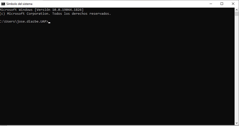
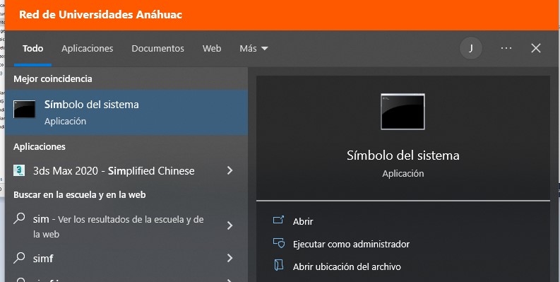
(7) Programming.
We run the command prompt.
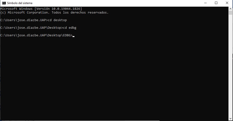
(8) We enter the location of our EDBG file and bootloader, in my case
Desktop > EDBG
(9) We execute the command
edbg-windows-r38.exe -ebpv -t samd11 -f free_dap_d11c_mini.bin
If you have a version other than 38 you must change the version number. R38, R39…
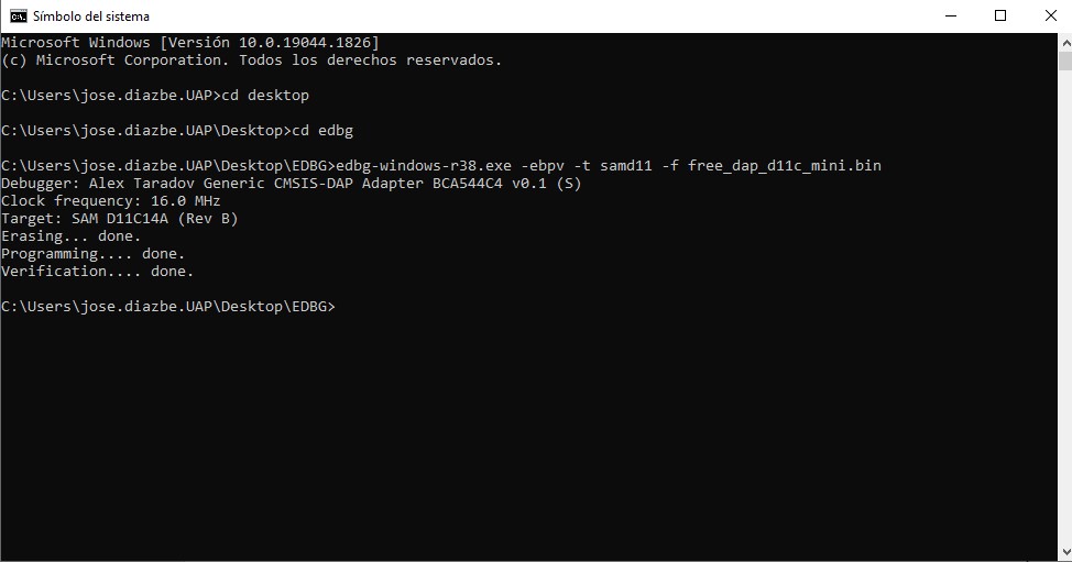
(10) If everything goes well you should see something similar to this, otherwise re-check the quality of the assembly of the components or the connections.
Note. The functional programmer must be connected via USB to the PC and the new programmer must be connected to a different power supply, in my case a 5V eliminator.
Now when connecting our new programmer the PC will recognize it as a functional device.
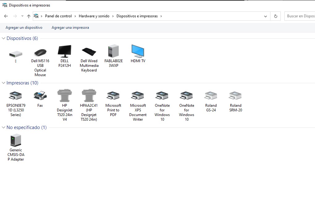
(11) This is what our ready programmer looks like.
(12) Now it's time to upload the bootloader to the Guitardino so that it is programmable from the Arduino IDE.
For this process we need:
1. EDBG latest version, you can download it from here.
https://taradov.com/bin/edbg/
Select the corresponding operating system and version.
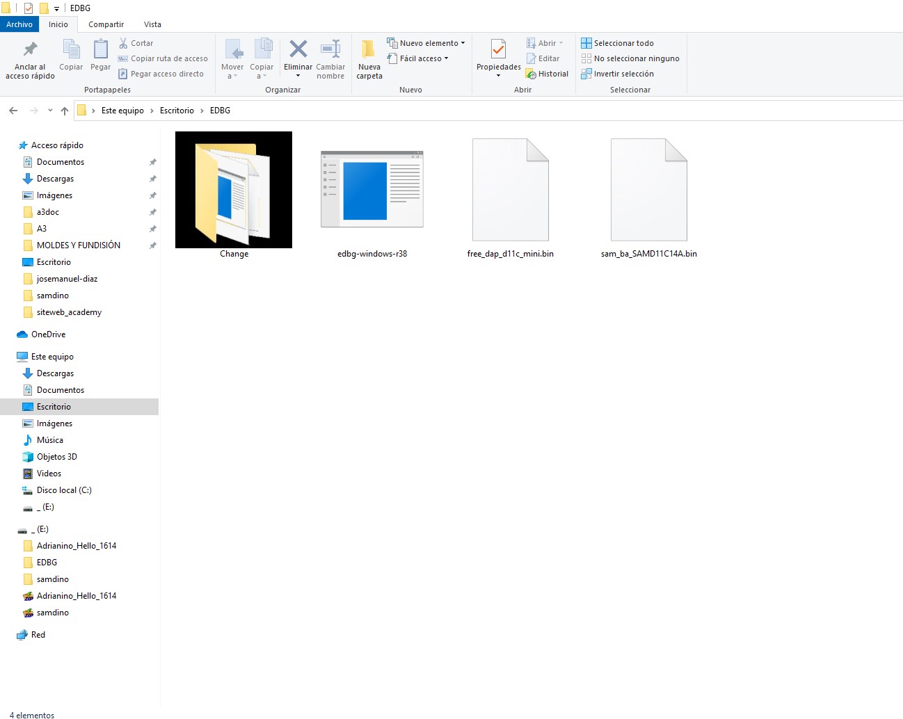
2. Bootloader (will allow us to program the board from the Arduino IDE)
You can download the latest version here.
https://github.com/qbolsee/ArduinoCore-fab-sam/blob/master/bootloaders/zero/binaries/sam_ba_SAMD11C14A.bin
All of the above should be in the same folder.
3.SWD-D11C programmer
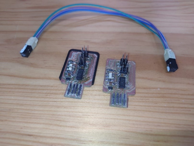
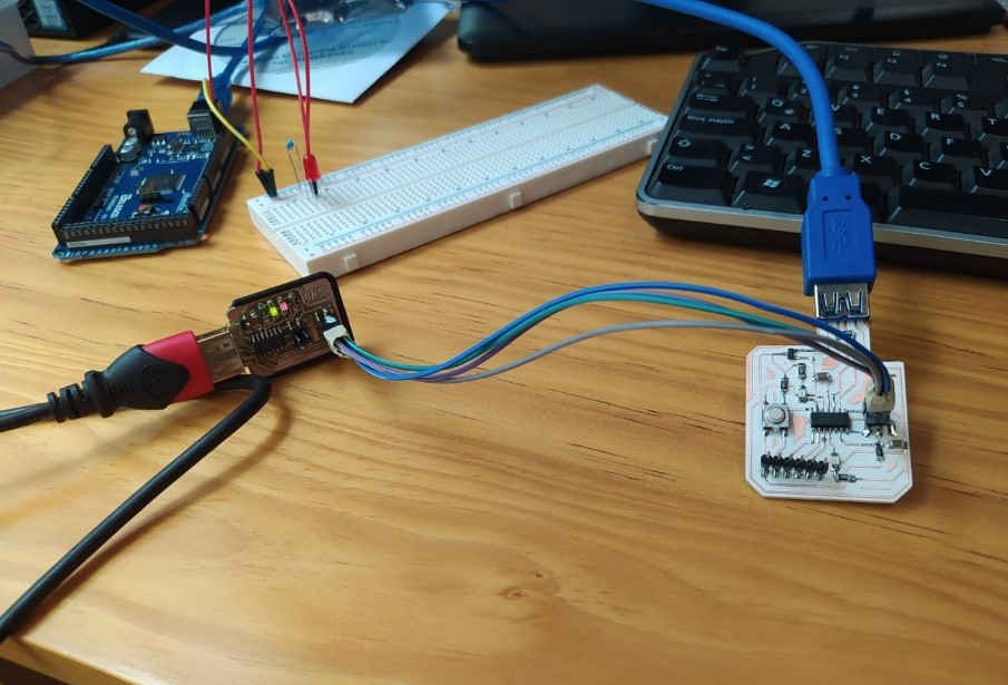
4. If like me you use a SWD programmer you will only need a cable made with 4 female-female jumpers to communicate the programmer with the Guitardino.
5. Lastly, we need two USB extension cables. Once the connections of the programmer and the Guitardino are made, they look like this.
(13) The SDW programmer must be connected via USB to the PC and the Guitardino must be connected to an external power supply, in my case a 5V eliminator.
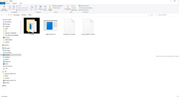
(14) This is what the folder with the corresponding files looks like:
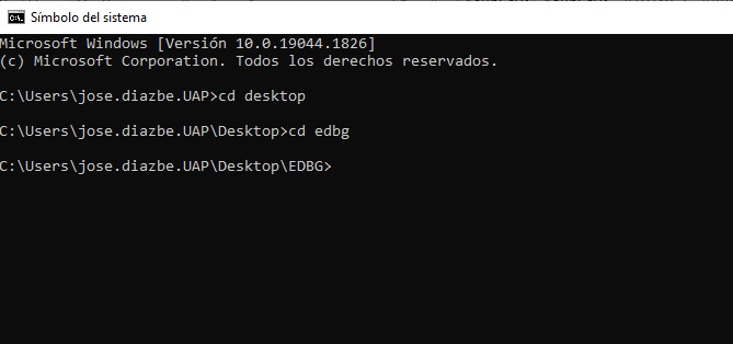
(15) We run the command prompt
(16) We open the location of our folder:
(17) We execute the command
edbg-windows-r38.exe -ebpv -t samd11 -f sam_ba_SAMD11C14A.bin
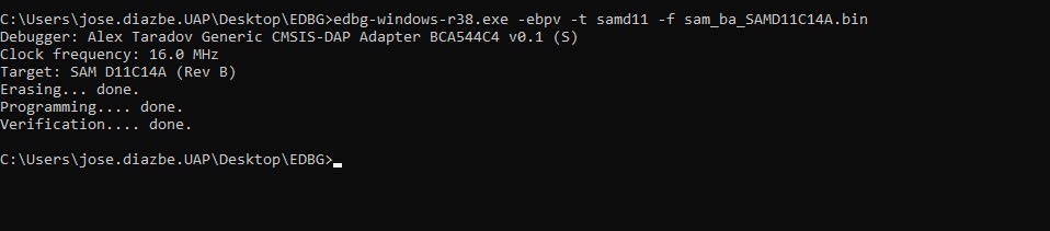
(18) If you have a version other than 38, you must change the corresponding version number: R38, R39, R40...
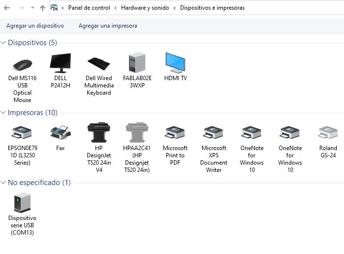
When connecting the board to the computer, the system should recognize it as an out-of-the-box device (COM13):
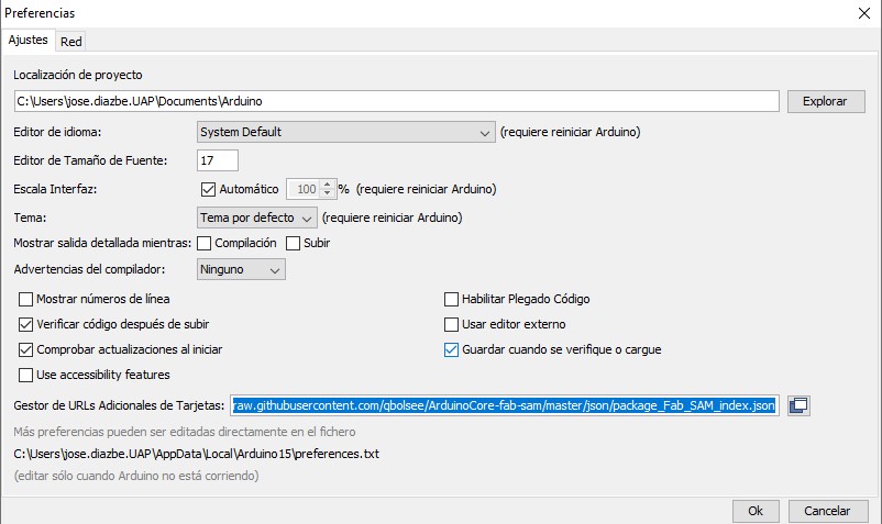
(19) From the Arduino IDE we need to do a few extra steps before we can program our board. First we must add the following link in the additional card manager:
File > Preferences
https://raw.githubusercontent.com/qbolsee/ArduinoCore-fab-sam/master/json/package_Fab_SAM_index.json
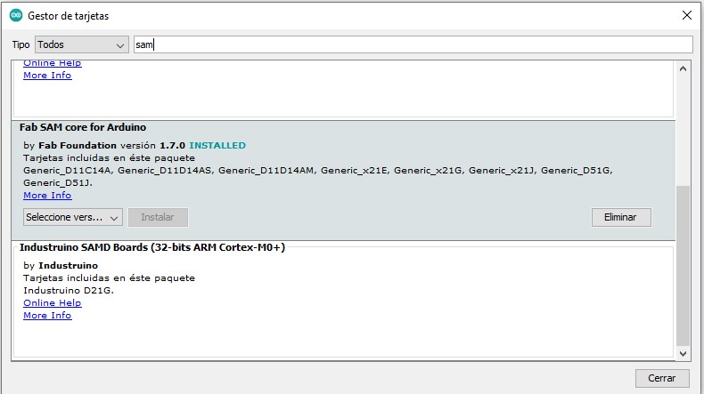
(20) Then we must download Fab SAM core for Arduino
Tools > Plate > Plate Manager
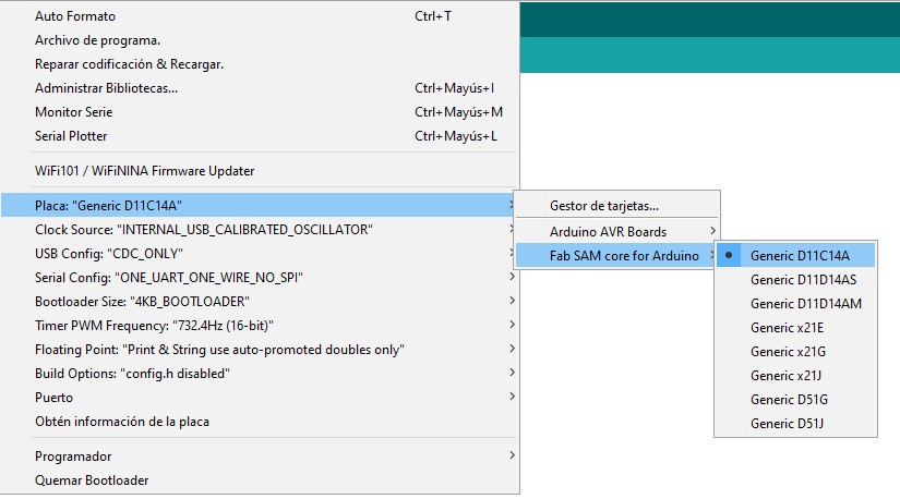
(21) We choose the Generic D11C14A Microprocessor
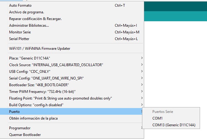
(22) And we choose the corresponding port.
(23) Before starting with the programming of the board, it is important to remember some important points from the data sheet of the SAMD11C
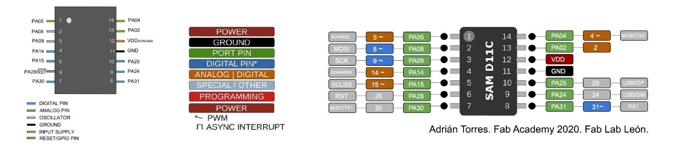
(24) I found this image which was very helpful to understand the nomenclature and configuration of each pin. I reviewed it in the electronic design week, but this week it has been very useful for me to declare the pins from the Arduino IDE, also to know if they allow to work with analog or digital inputs/outputs.
I made the following image as a wild card to have at hand the nomenclature of VDD, GND, LEDS and programmable pins.
(25) For programming with Arduino, the following resources have been of great help:
https://www.arduino.cc/reference/en/
https://www.udemy.com/course/arduino-desde-cero-con-tinkercad/
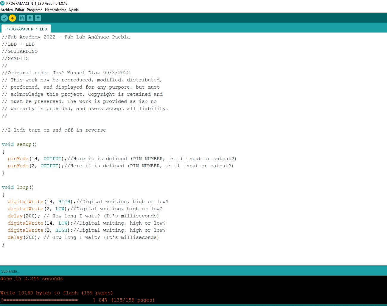
The first thing I did was program the LEDs that are already integrated into the Guitardino, first make them turn on and off in reverse:
**********************************************************
Two leds turn on and off in reverse.
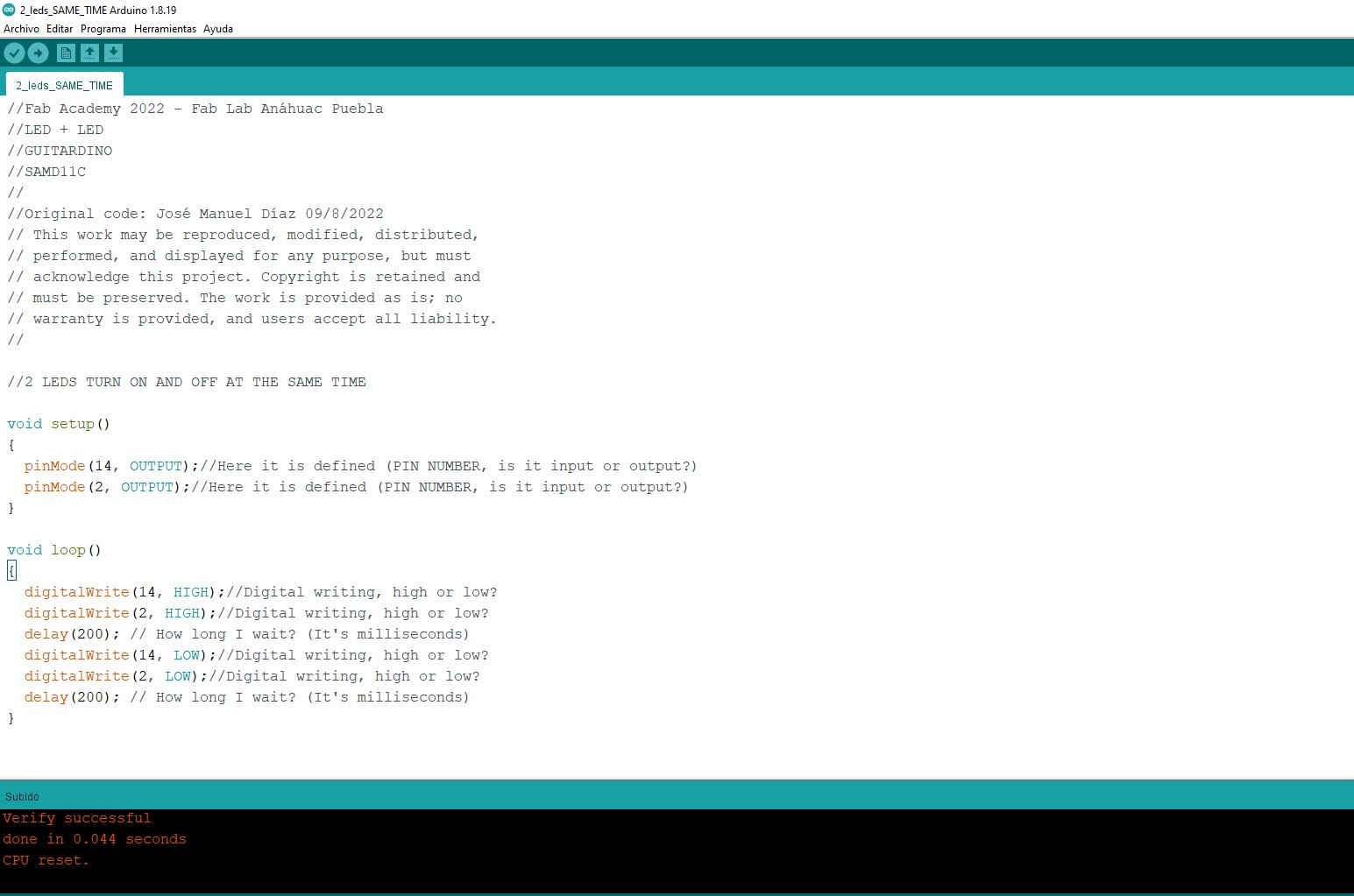
(26) The following program was a variation of the previous one, now the leds turn on and off synchronously.
****************************************************************
Two leds turn on and off at the same time
(27) In electronics, a digital to analog converter (DAC) is usually used to transform the digital signal into analog, however, the Guitardino does not include a DAC within the circuits that make up the board, so it is not capable of produce analog outputs. However, they are capable of producing a PWM pulse modulated analog signal.
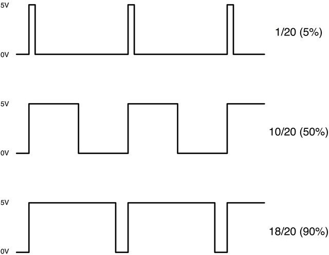
PWM (Pulse Width Modulation) is a type of voltage signal used to send information or to modify the amount of power being sent to a load. This type of signal is widely used in digital circuits that need to emulate an analog signal, in which the relative width is changed with respect to its period, the result of this change is called duty cycle and its units are represented in terms of percentage.
(28) Source:
https://www.programoergosum.es/tutoriales/salidas-analogicas-con-arduino/
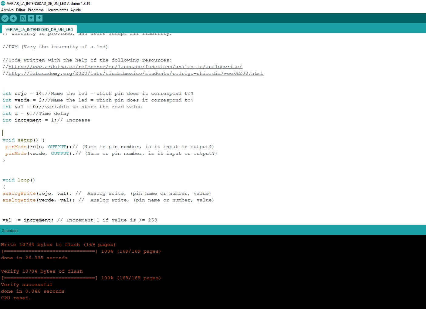
With this theory I decided to create a code to vary the intensity of the Guitardino's leds, to give a gradient effect.
********************************************************
Vary the intensity of two PWM leds
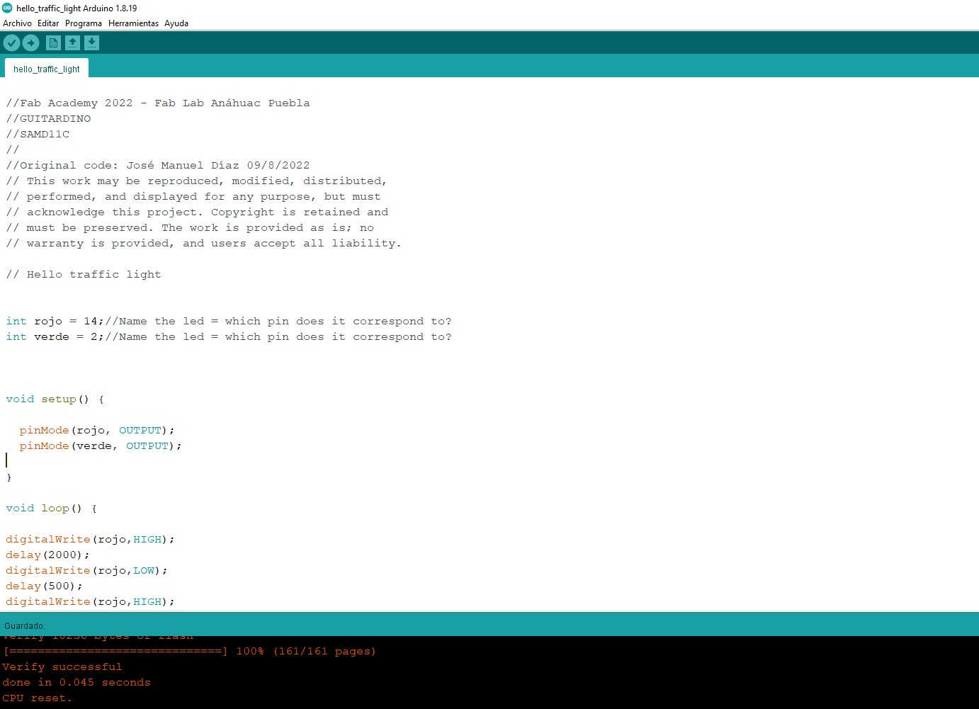
(29) I also wrote a very simple code to emulate a traffic light with the Guitardino's leds, in this example the leds stay on and blink before changing to the next color.
*********************************************************
Traffic light with integrated leds.
![]()
Additional experimentation
![]()
(30) By this time I was very excited to see what can be achieved with a few lines of code, it's a kind of controlled magic :D.
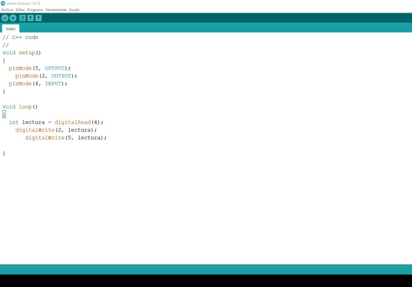
So the next experiment was with a 3V DC motor, for this I used the button on the Guitardino so that pressing it will activate the motor. The result was the following:
***********************************************
3V Motor + Button
*********************************************************
(31) Photoresistor to turn on an LED
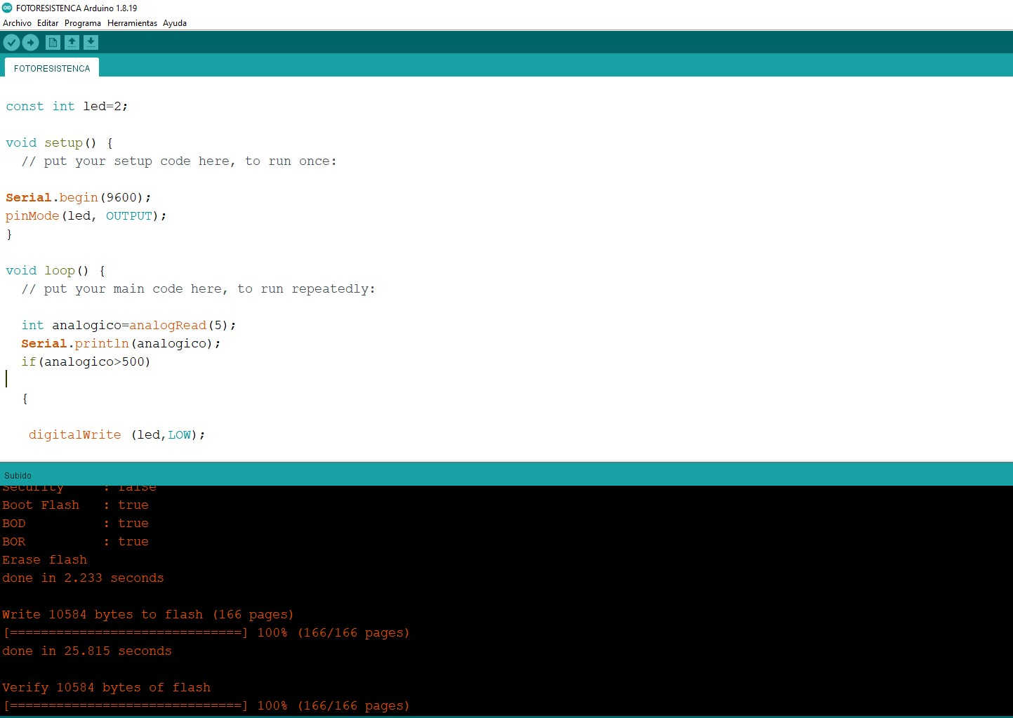
Finally, I did a very fun exercise with a resistance photo.
“A photoresistor is an electrical component, which has a resistance capable of varying its magnitude when in contact with different magnitudes of light intensity.
It is made up of a photoreceptor cell and two pads; when said cell no longer perceives a certain level of light (that is, when it drops below the predefined minimum lumens), then it makes contact and the lights come on.”
Source: https://como-funciona.co/una-fotorresistencia/
The objective is that when there is little light one of the integrated LEDs turns on, this example is an approach to the automation of a house, that when there is little lighting the intelligent system turns on the required lights.
![]()
![]()
Conditional statements
On the recommendation of my global reviewer I decided to do some additional code where I explored conditional statements. In this code I used if and else so that when the button is pressed, led 2 blinks and when it is off, led 14 blinks. I added the state variable, where the state of the button will be stored and from there the program will decide if led 2 or 14 turns on
const int LED1=14;
const int LED2=2;
const int BOTON=4;
void setup() {
// put your setup code here, to run once:
pinMode(LED1, OUTPUT);
pinMode(LED2, OUTPUT);
pinMode(BOTON, INPUT);
}
void loop() {
// put your main code here, to run repeatedly:
int lectura = digitalRead(BOTON);
if (lectura==LOW)
{
digitalWrite (LED1,HIGH);
delay(500);
digitalWrite (LED1,LOW);
delay(500);
}
else
{
digitalWrite (LED2,HIGH);
delay(500);
digitalWrite (LED2,LOW);
delay(500);
}
}
![]()
You can download de Files HERE
Code 2 leds inverse
Code 2 leds same time
3V Motor
Photoresistor + LED
Hello_traffic_light
![]()
Copyright 2022 Jose Manuel Diaz Bello